I spent the first part of this week finishing up programming my FabISP and machining my Hello World board, which I didn't have the chance to do a couple of weeks ago. For the FabISP, my debugging was mostly done by doing continuity testing with a multimeter. http://en-us.fluke.com/training/training-library/test-tools/digital-multimeters/how-to-test-for-continuity-with-a-digital-multimeter.html. In particular, it was helpful to test the major components (USB, microcontroller, 6-pin connector) to see if they were connected correctly. In the end, I managed to solder my USB and 6-pin connector correctly, and finally finished programming by FabISP. During the course of this, I found it useful to use a smaller soldering iron in order to get more precision when soldering and when desoldering using a soldering wick.
Next, I milled my Hello Word board. I followed the same steps that I did when milling the FabISP, making sure to put on enough tape. The only complication that I ran into was when milling the outline: I didn't have the same alignment for the outline and for the traces, so my outline overlapped with some of my traces and I had to remill.
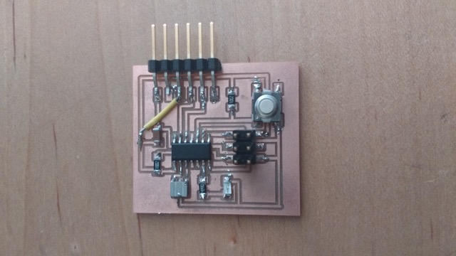
When stuffing the board, I had to pay attention to the polarity of the LED. The LED that I used has a stripe on one end, which denotes the cathode (on an electrical diagram, this is also the end which has a line).One other problem occurred when I attempted to program my Hello World board using my FabISP.The board seemed to program fine, but when I removed the 6-pin connector, some of the traces for my board got ripped out. In order to fix my connections, I managed to solder an insulated jumper wire onto my board. Surprisingly, this worked out well.
The next step for this week was to write a program to turn on the LED light when the button is pressed. My main resource for doing this were http://fab.cba.mit.edu/classes/4.140/doc/tutorials/programming/Simple_examples/c_prog_examples.html and http://www.elecrom.com/2008/02/12/avr-tutorial-2-avr-input-output/. The attiny44 has two ports, A and B. Each port has three 8-bit registers (though for the B port, only the lower 4 bits are used). These registers are the DDRx, PORTx, and PINx registers (where x is either A or B). The DDRx bits determine whether the pin is input or output: 1 denotes output while 0 denotes input. PINx reads data (low or high) from the pin: the corresponding DDRx register also has to be set to input. PORTx outputs data/pulls up registers: 1 pulls up resisters/sets a high voltage, while 0 pulls down resisters/sets a low voltage. The corresponding DDRx register also has to be set to output.
For the Hello World LED, if the button is pressed (voltage on button pin is low, as read from PINx), then the voltage on the LED pin is set high (PORTx is set to 1), which allows current to flow through the LED. Otherwise, the voltage on the LED pin is set low, turning the LED off.