Week 10: Output Devices
LED Array and Pressure Sensor Combo
Nov 23, 2016
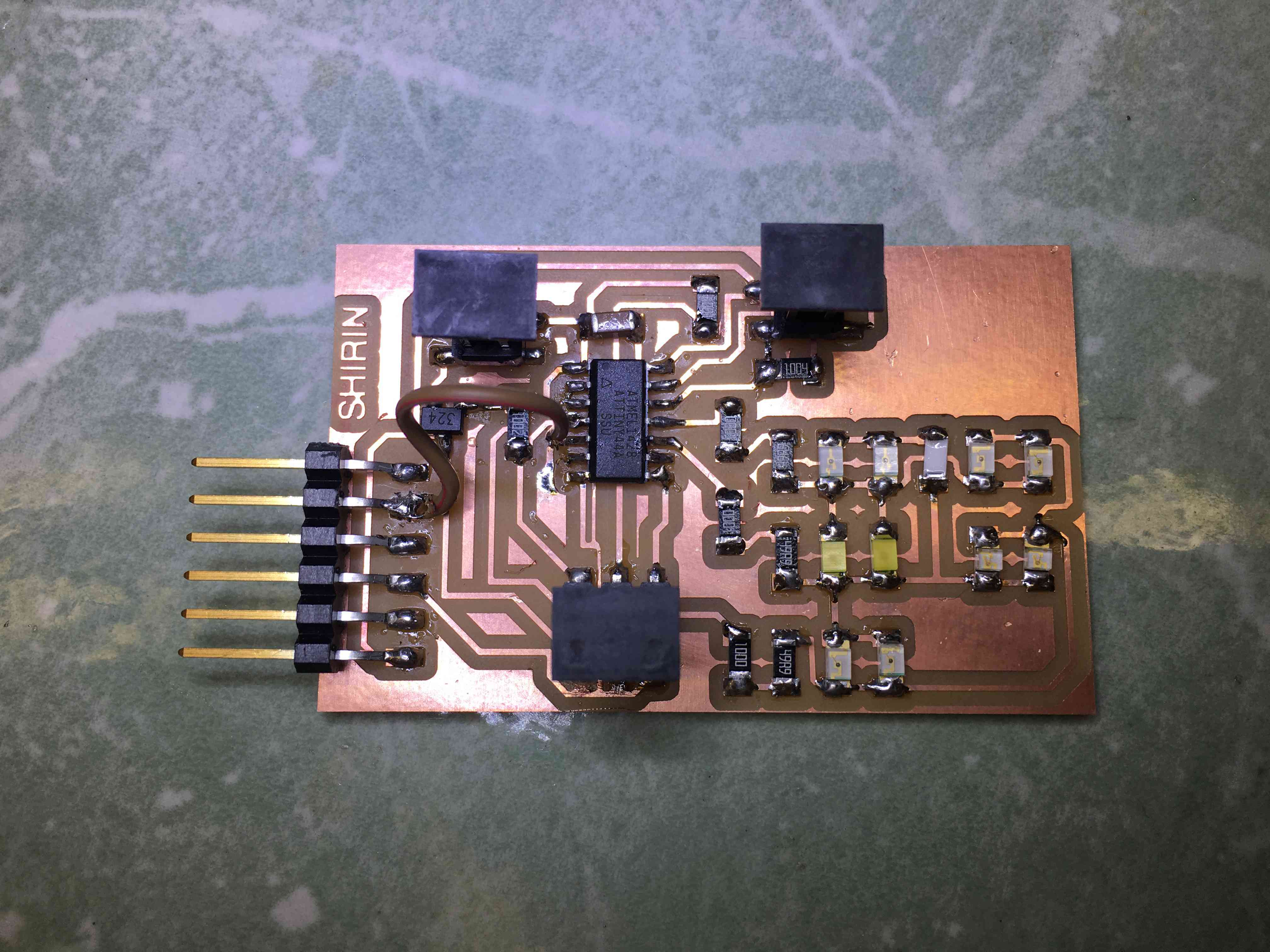
For my final project, I want to make a central board with the micrcontroller on it and 5 peripheral boards each containing a couple of LEDs and a pressure sensor. To save pins, it makes sense to do charlieplexing. So this week, I added and LED array to my attiny44 hello-world board and combined it with a txrx step response sensor, used as a pressure sensor. When you apply a certain pressure on the baord, the LED array will light up!
Assignment
Add an output device to a microcontroller board you've designed and program it to do something.
Main tools used this week: Eagle, Roland SRM-20.
Board Design
Ranting about KiCad
This week, I wanted to try using Eagle instead of KiCad. I went through a few sparksfun tutorials and picked it up very quickly. In my opinion, eagle is easier to learn than kicad. A couple of things I really liked about it:
- You can add your own shortcut keys (although I'm not sure how to save the settings, so you don't have to do it every time!)
- Autorouting works nicely and makes your life so much easier! Kicad doesn't still have an autoroute option.
- Adding libraries is more straightforward than kicad. For instance, in Kicad, I had to manually match every fablab schematic symbol with its footprint, but in eagle they were all matched.
- Importing from schematics to board occurs automatically and updates transfer easilu most of the time.
- You can export a png image of the board layout, where as in Kicad I could only export dxf. Even then, I couldn't figure out a way to export only the board area without, while maintaining its size. Since the export was dxf, I also had to modify the background color from transparent to white. Too much postprocessing, while eagle just lets you export a neat png image!
Overall, I think Eagle is a great options for the scale of boards we make in this class. Although Kicad is an open-source tool and still developing, it doesn't beat Eagle.
Now that I'm done with my ranting...
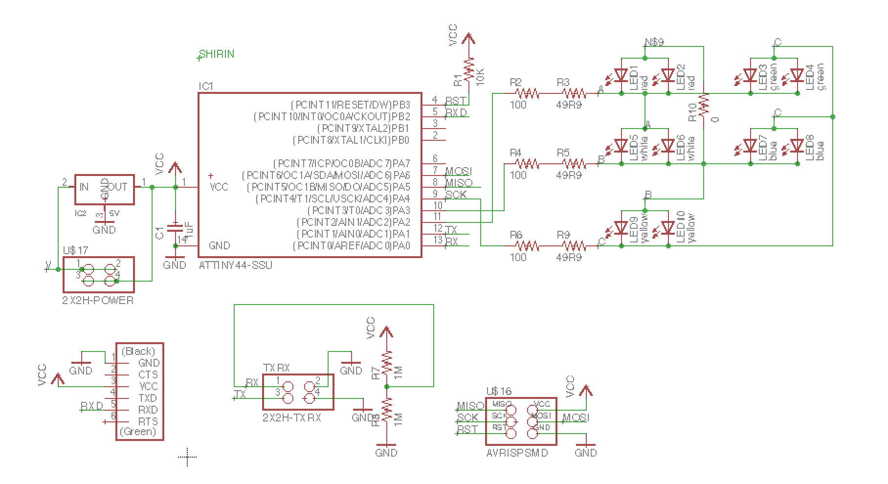
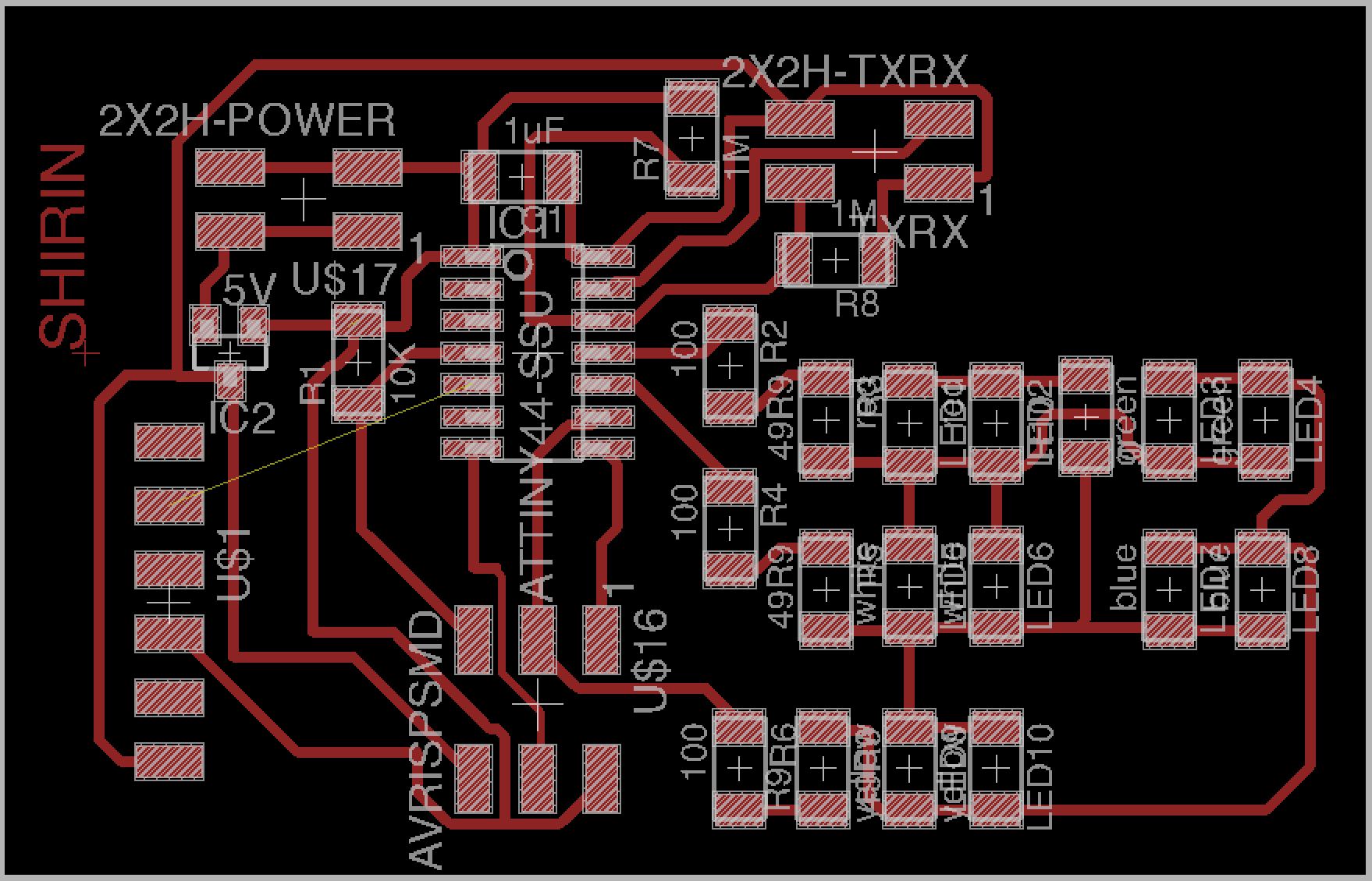
My board design
First, I had to figure out how charlieplexing works. This instructable explains the theory behind in simple words.
I wanted to use 2 leds in parallel to light up a larger region. So I used two resistors in series to make 150 ohms (and a larger current out of the pin). It turns out you can use MOSI/MISO/SCK as I/O pins, as long as you don't draw more than ~40 mA from the pin. So I used a pin for both and one row of the LED array.
I couldn't find a way to route the RXD signal, so I connected it with a jumper wire.
A problem I ran into in Eagle was when I made changes to rx-tx pins on the schamtic, for some reason they didn't transfer to pcb, and my board and schematic got disconnected. I had redo the wire names to correct it.
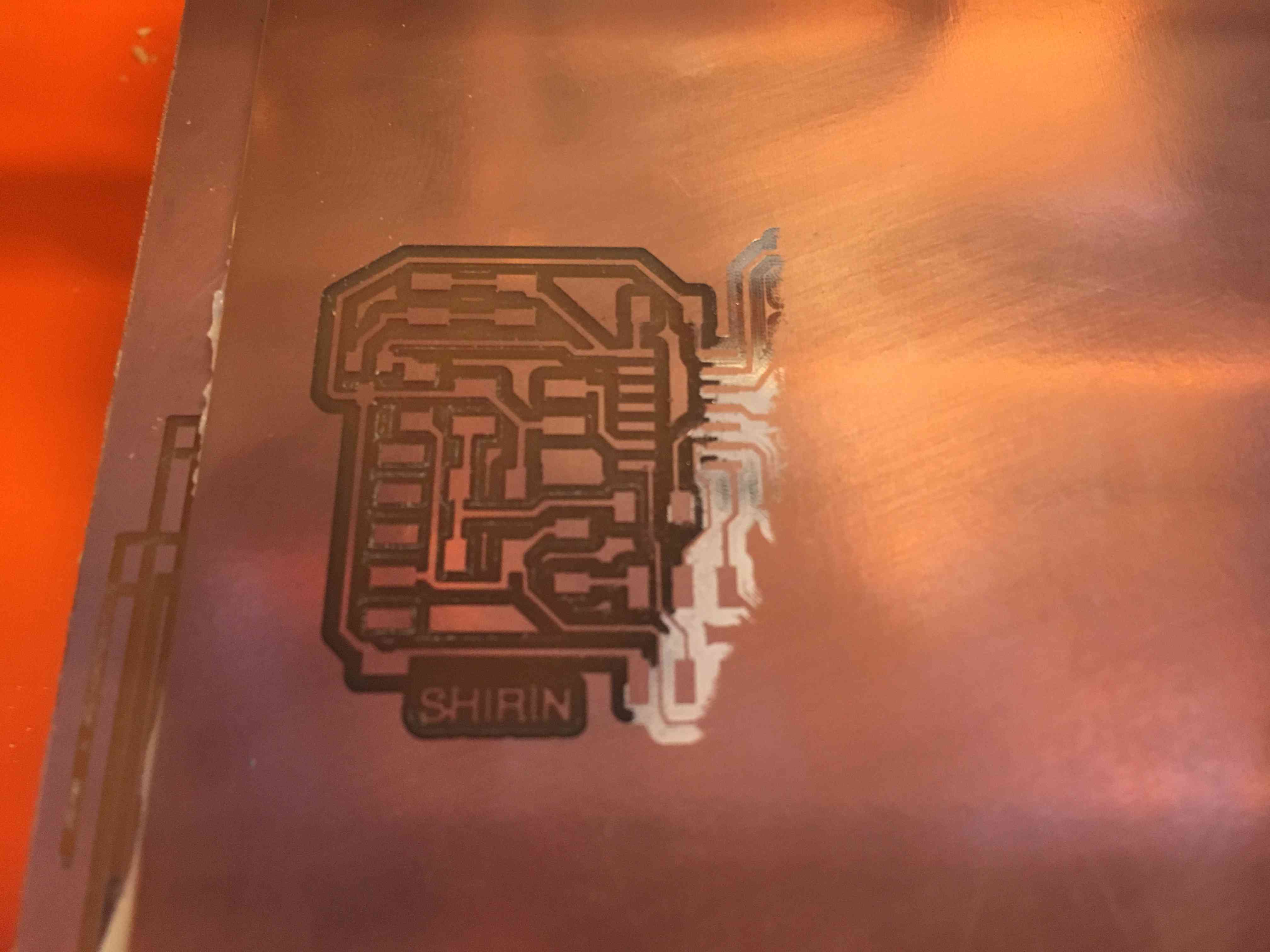
I made a common mistake, where the tapes on the bottom side of the board were overlapping in the middle. The height of the board wasn't the same everywhere.
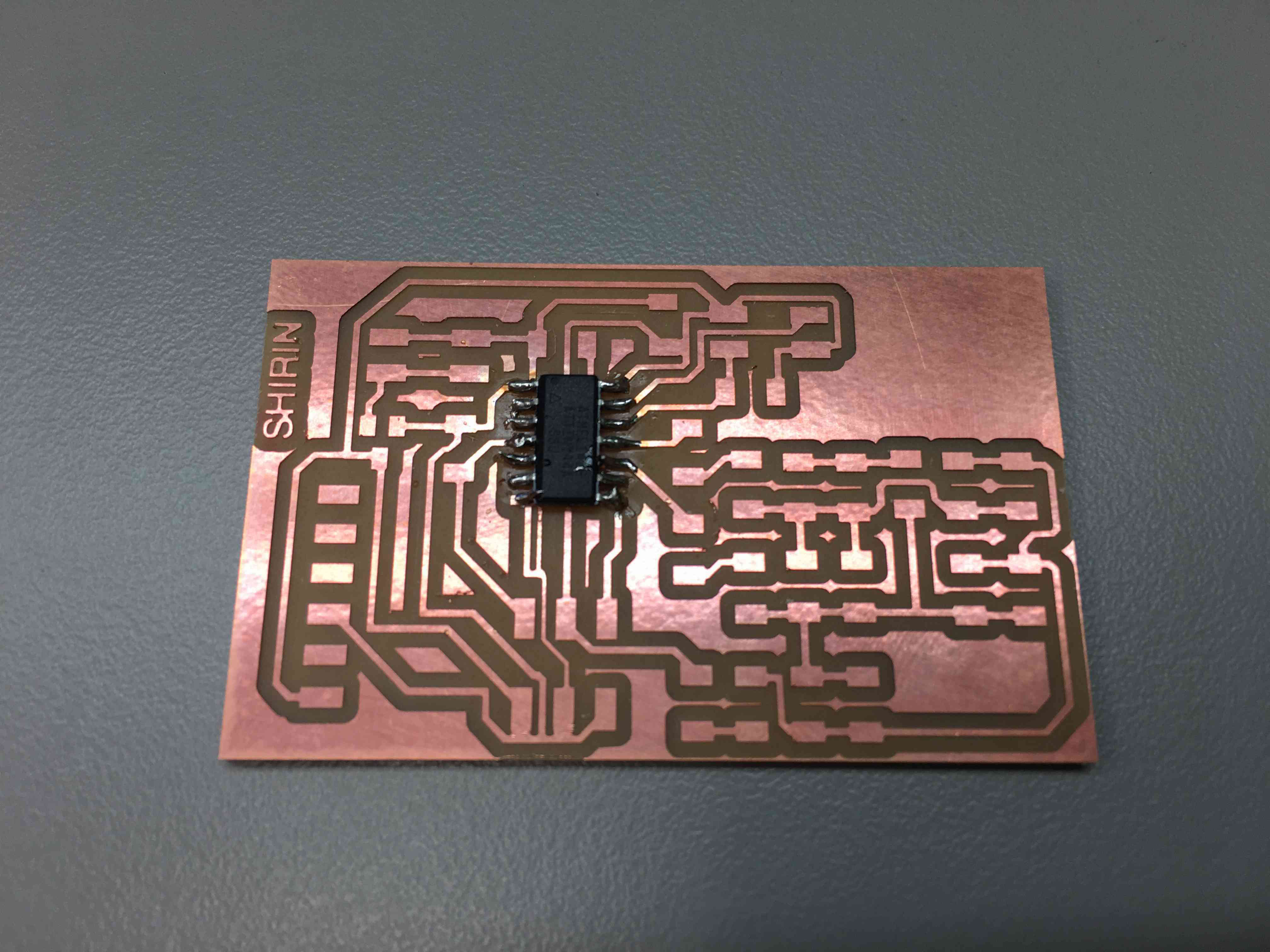
This time milling went fine but I found a couple of shorts. I used a razor blade to cut them. I think a clearance of 0.015 between traces was not enough, because I should have accounted for tool tolerance.
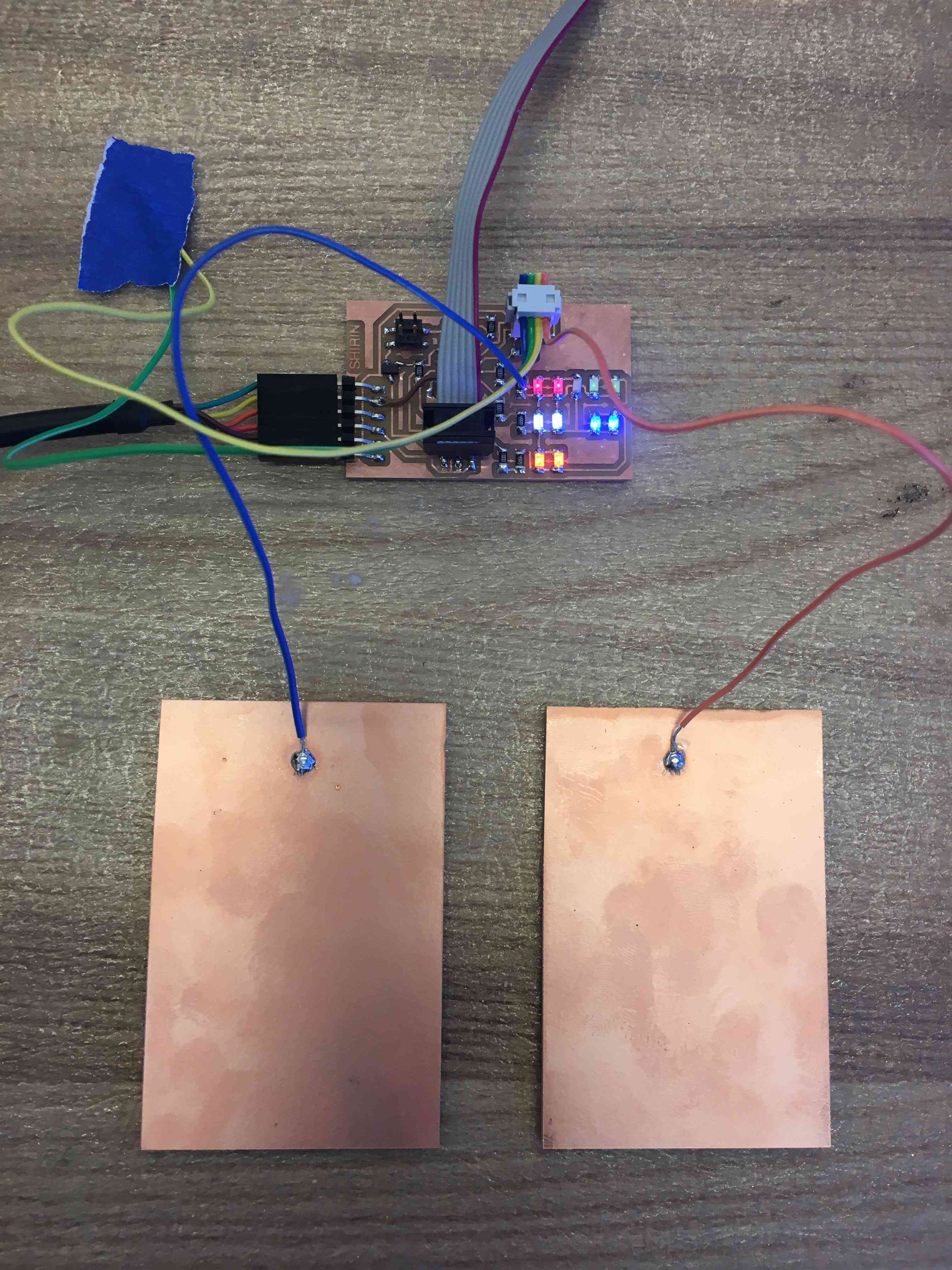
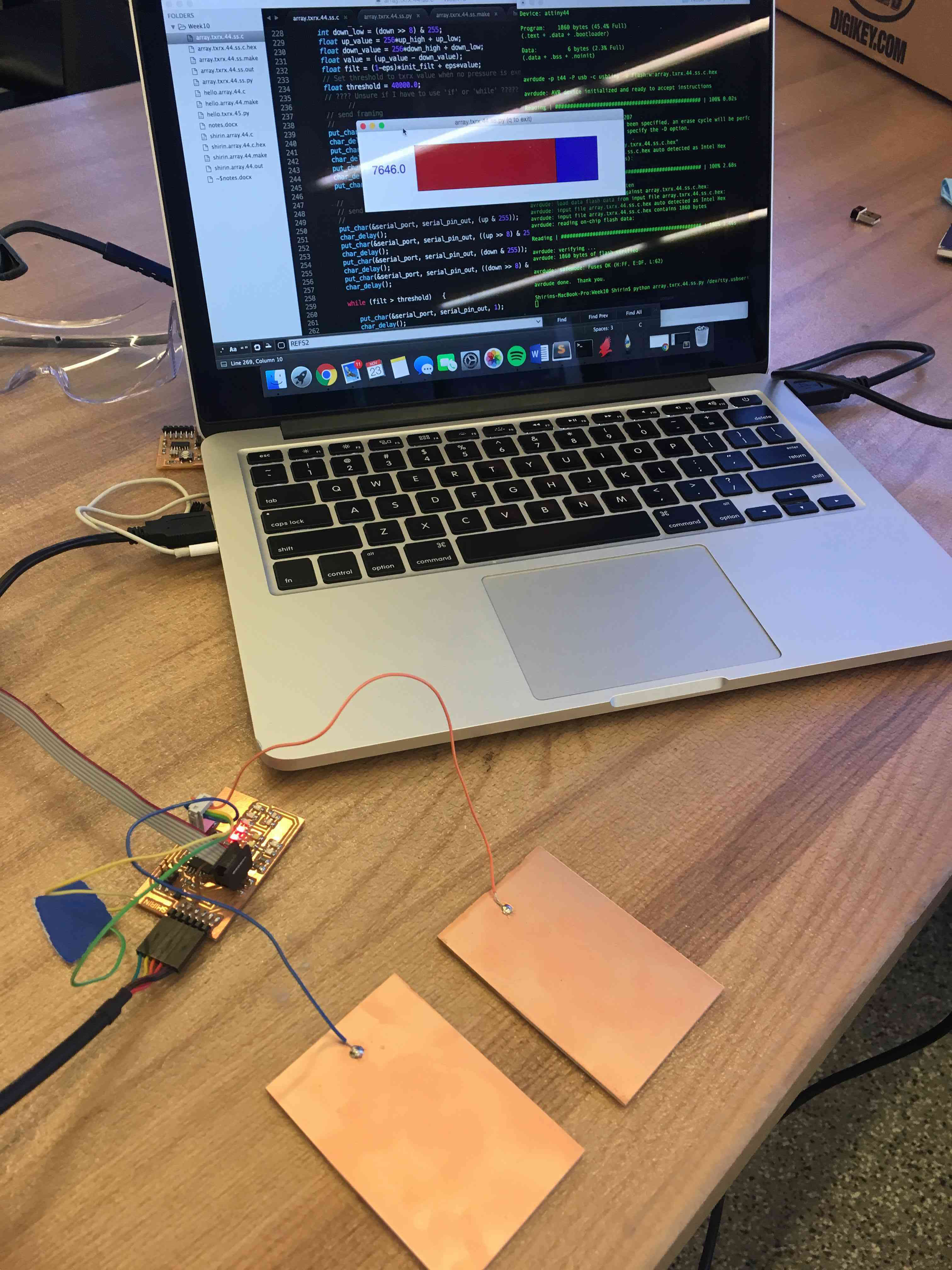
The array and the sensor worked separately, but I wasn't able to make the array respond to the sensor. This is my code.
A previous student, Harry McNamara, modified Neil's step resposne code so that it senses the change in the E-field instead of an absolute value. I may adapt his approach for the next weeks.