Week 12: Networking and Communications
I2C Interface
Dec 7, 2016
For my final project, I need 5 peripheral boards for each region of the brain. Each peripheral board will have a txrx sensor to sense pressure and a set of LEDS that light up in response to a change of pressure. For this week, I used the I2C module to communicate between my devices. Compared to SPI, I2C allows using the same data line to communication with multiple lines, therefore saving pins on the microcontroller.
I made two simplified peripheral boards that have a txrx sensor and an LED. The main board has one LED to indicate if master has received a message from the slaves or not.
Assignment
Design and build a wired and/or wireless network connecting at least two processors
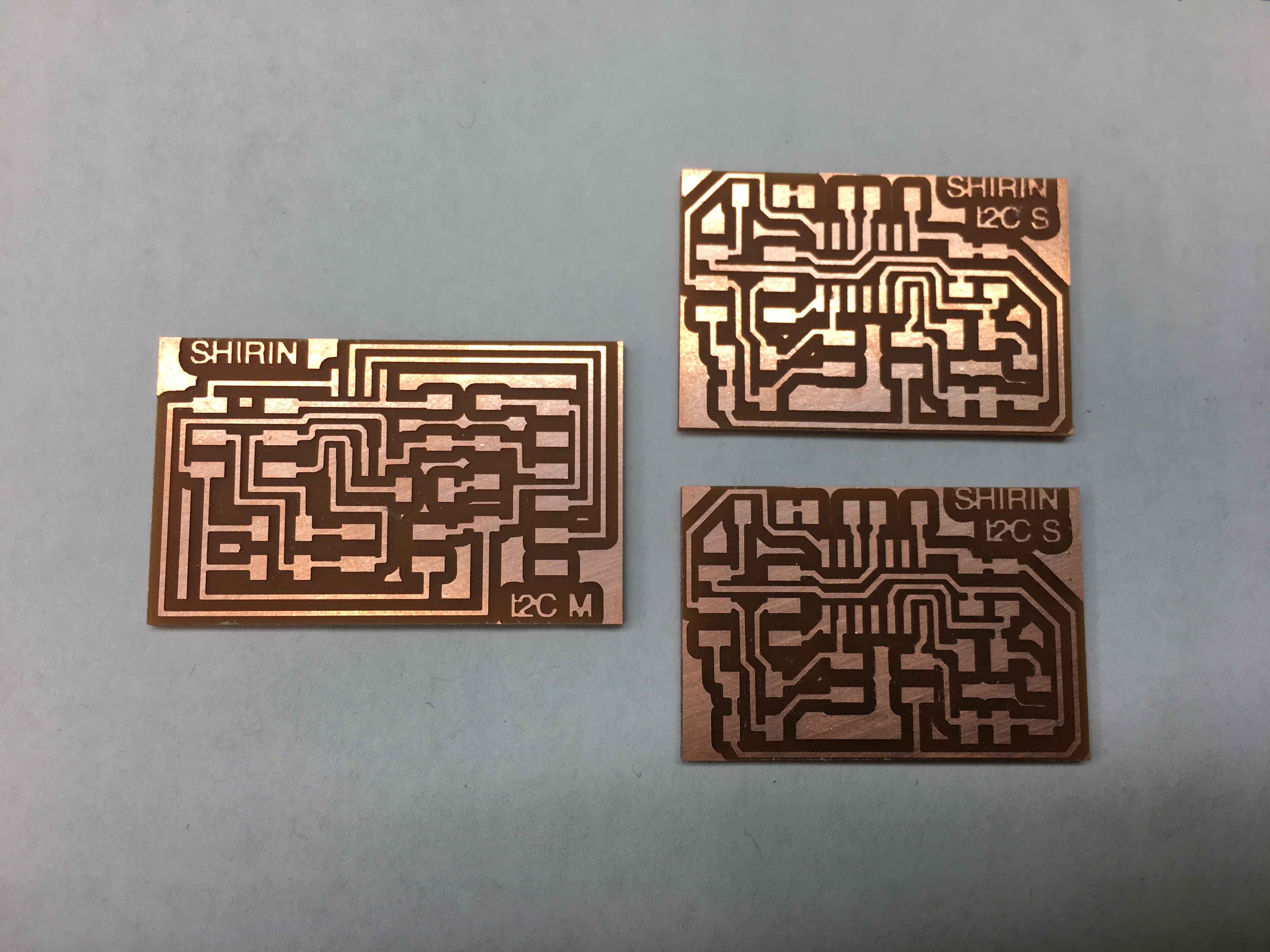
Board design
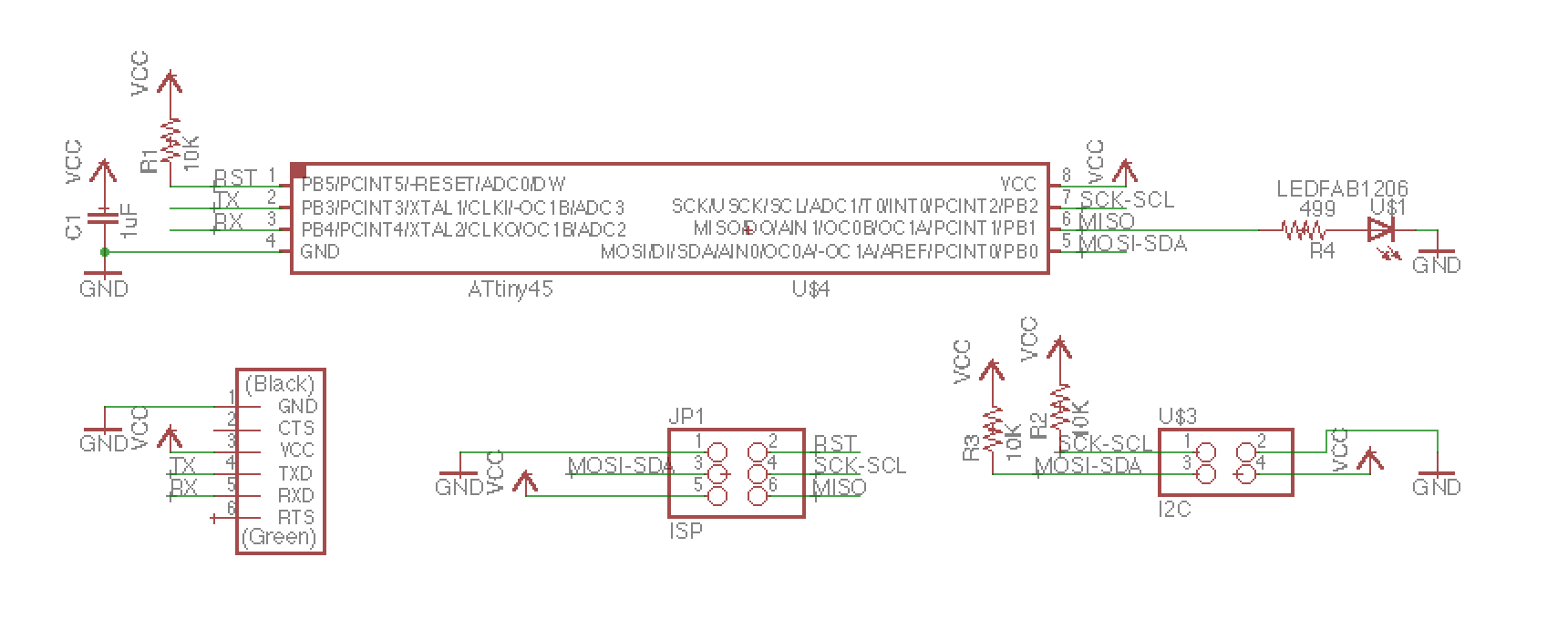
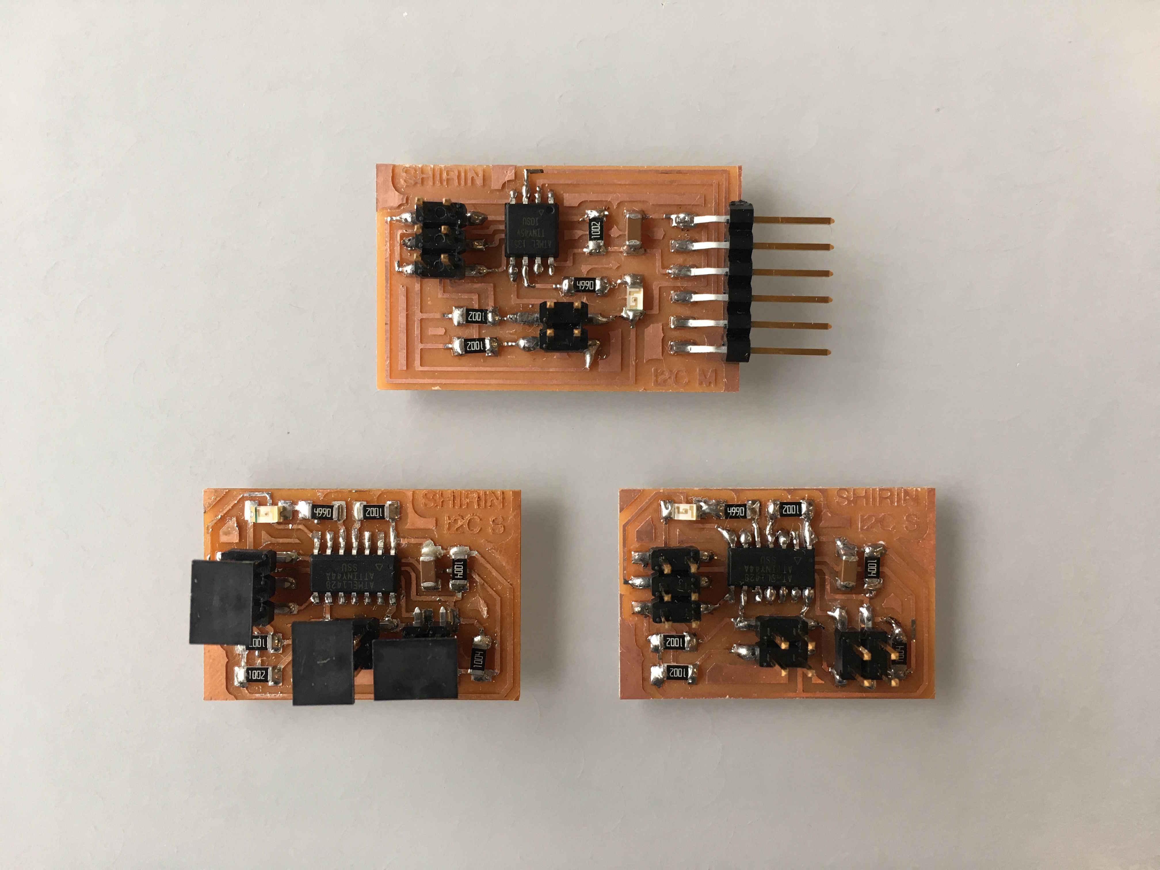
For the master board, I used an attiny45 similat to Neil's example, and added a LED for debugging to indicate if the board has received a message from one of the slave boards.
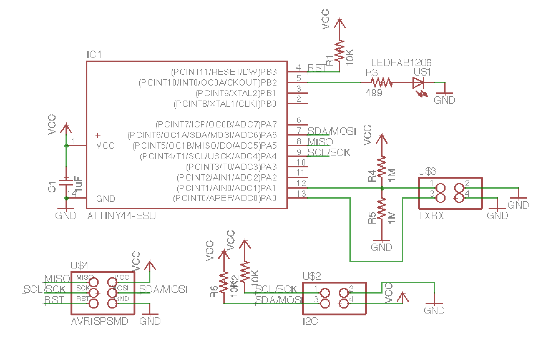
The slave boards have a txrx sensor and a LED. I had to use attiny44 for my slave boards. Because I wasn't sure if I could reuse SCL and SDA pins on attiny45 for sensors, I needed more I/O pins.
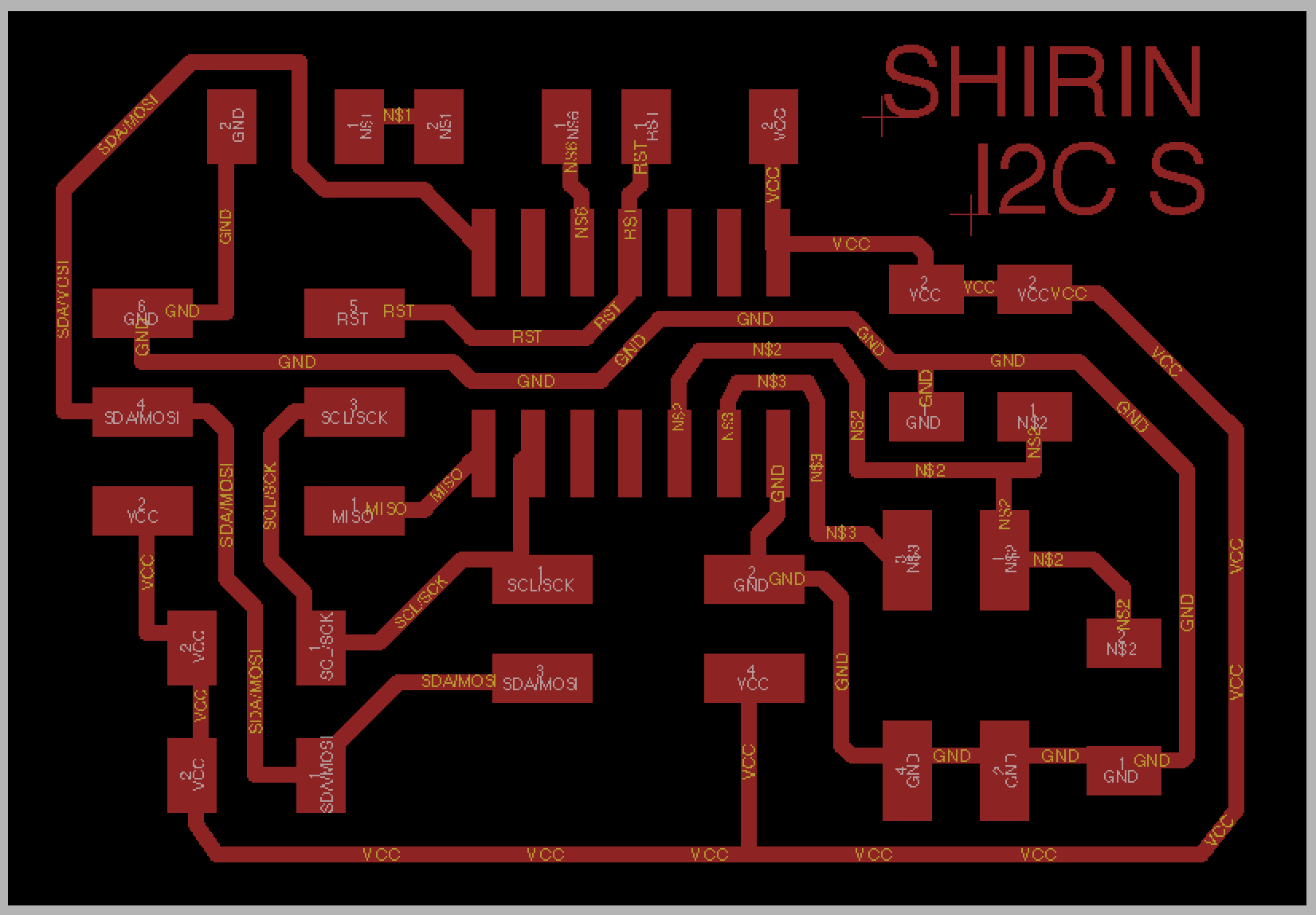
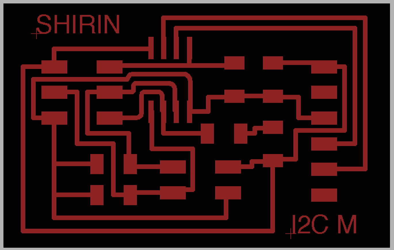
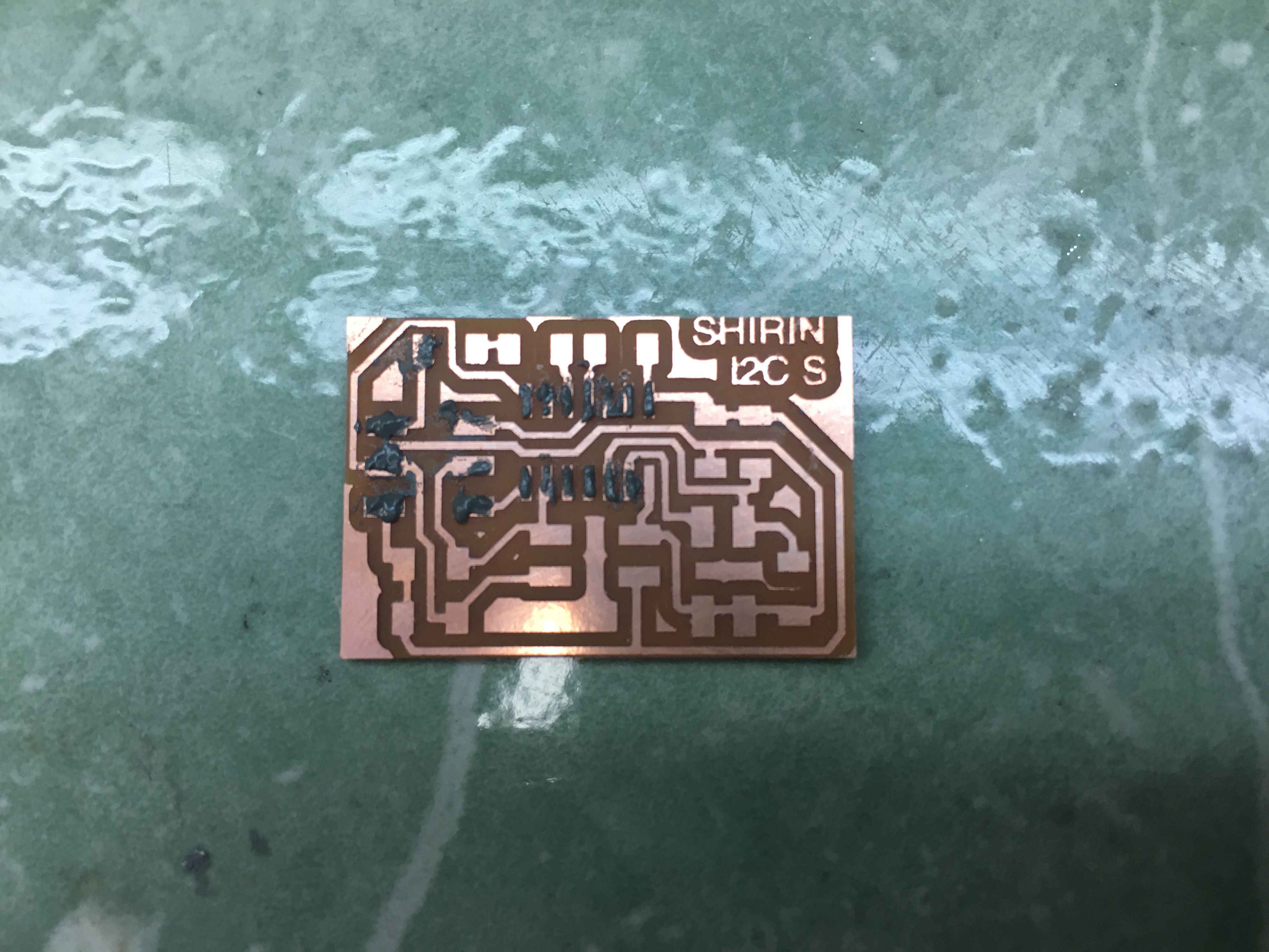
Here's the printed board.
Following one of the classmate's suggestion, I deicded to give solder paste a try this week. By now I'm fast enough in soldering though that I don't think solder paste is worth using for just one board. I think it will make my life easier for my final project where I have to solder five boards and I can put them in the oven all at the same time.
Programming
It took me a while to understand the I2C prottocol and how it's implemented in firmware. Basically, attiny has USI (Universal Serial Interface) which you can use for TWI (Two-Wire Interface), a module that basically does I2C and more. However, we use bit-banging, meaning we implement the protocol in software rather than hardware. Neil's hello.ADXL343.c code is helpful to see how I2C is done in code. For instance, it initiates communication by manually driving SDA LOW and then driving SCL low.
Fist thing I tried to do was to just program the master board, which worked. Then I connected the master board to one slave and programmed the master again, hoping that I would be able to flash an LED on the slave board, which didn't do anything.
Next, I tried to directly program the slave board, while it was connected to the master board (and the master connected to computer with ftdi). Although the board was programmed, it didn't do anything either. And then the the smell of burnt electronics... my master board stopped working. Realizing that I didn't know what I was doing and was just trying randomg things, I decided to stop and take this on again after consulation with a TA.
Some of my unanswered questions are:
- What's the advantage of using I2C comapred to asynchronous serial?
- Do I program master and slave boards separately? Or Do I program the slave via the master?
- Do I only need one c code that includes firmware for both master and slave, or do I need sepaarte ones?
- The master board works with attiny45 and the slave works with attiny44. How does this affect the code?
UPDATE: I figured out why I burnt my board. I didn't pay attention to the direction of I2C header, and I think I connected VCC of one board to Gnd of another.