Week 5: Computer-Controlled Machining
Make Something Big
Oct 19, 2016
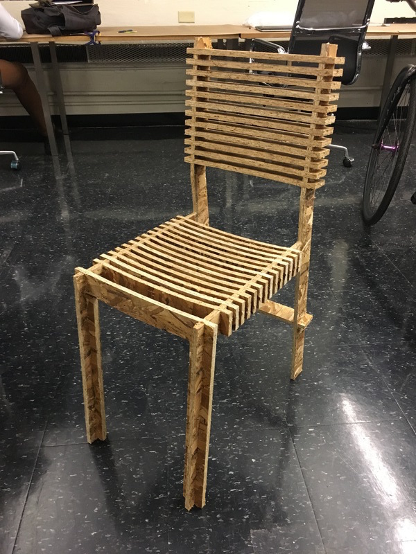
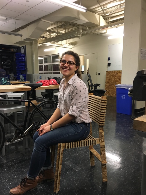
Press-fit Chair
I always have a lack of chairs in my room when I have friends over. So this week, I decided to make a chair for my room. I was inspired by this design on opendesk to make a press-fit chair. I made a 3D model of in Fusion360 and unfolded it in Rhino, cut the pieces from OSB with the CNC router in IDC and filed them at the end. Here's the final chair (which I would not ask anyone to sit on...)
 |
 |
Assignment
Make something big!
Main tools used this week: ShopBot CNC router, Fusion 360, Rhino.
Basic Knowledge
ShopBot CNC router: What we'll use this week for machining.
Material: These are the some of the material used commonly with the ShopBot router. These material are usually bought from local vendors or Home Deopt:
- Oriented strand board (OSB): Cheap plywood used for this week's assignment.
- Medium density fiberboard (MDF): Doesn't bend. Good for continuous structures.
- Medium density overlay (MDO): Smooth surface. Better structural proporties.
- Aluminum
Tooling:
- Tool diameter
- Diameter of shank
- Number of flutes: Less flutes means faster machining, but worse finish surface.
- Drill bit vs. end mill: Drill bit drills in place (doesn't cut sideways), wherase end mill is used for cutting.
- Note: How deep you can go in each pass is roughly the tool diameter.
Kerf: Milling not all the way through the material, in order to make continous hinges. It's how you make bendy fixtures. But OSB is too inflexible for kerfing.
Run-out: The difference between ideal cutting and what the machine actually cuts.
Conventional milling vs. Climb Milling: Two different ways of cutting material. Comventional milling leaves a rough finish. Climb milling levaes a smoother finish and is better for tool life, but using it depends on the machine.
Degrees of freedom: 2D pattern with restricted z-steps.
Cut depth: How deep the tool goes in each step- depends on tool diameter.
Clearance: Leave enough space in cuts for the tool to get in. Account for the shank diameter.
Joints: Instead of making simple square joints, you need to make dog-bone or T-bone corners. This way the mill has enough space to get in the corners.
Tabs: To cut parts that inside larger ones, cut inside out. Otherwise, leave tabs on edges of the parts.
Cutting air: Cutting above the object. Essential to do this first to avoid making mistakes on material.
Software: Any design software with parametric design. ShopBot comes with VCarve which is used to import vectors to the machien.
File format: ShopBot has its own part file format, but it also takes g.code.
Workflow:
- Parametric design
- 3D model
- Toolpath
- Check toolpath to make sure it makes sense
- Cut in air
- Test cut
- Make your thing.
Safety:
- Tie your hair!
- No loose clothing
- Parts can be hot and sharp.
- Work with someone
- Don't machine when you're tired
- Never reach under a machine tool
- Know how to stop the machine
Designing in Fusion 360
Autodesks's Fusion 360 is a good alternative to SolidWorks for designing 3D pieces. I had little experience in Fusion360, but I found this tutorial for making a flat-pack furniture very helpful to begin with. Parametric-design is a must for this kind of modeling. Under the Modify>Change Parameters menu, you can add user-defined parameters for things such as material thickness, clearance, tool diamaeters, and other important dimensions. This way, you can easily modify your design when you go in the shop. A few other considerations:
- If you copy and paste a component, you can modify one and all the copies will follow. If you paste new, a new and independent copy of the object will be made.
- If you need many copies of a component, you can create a pattern under the Create menu. Again by modifying one copy, the rest the pattern follows.
- Set the width of the joints slightly smaller than the measured material thickness and add clearance (I added 0.001").
- Create dog bone corners for the joints, making the radius equal to tool diameter + clearance.
One of the problems I encuntered at the end was that I used Assemble > Joint feature to attach components together. But then I realized this feature left the sketch behind and only moved the body of the component. So after making joints, I had a really hard time modifying the sketch especially for parts that I had made a pattern of.
I exported my file in .iges format and used the UnrollSrf command to make 2D drawings of my model.
Lessons Learned from Making the Chair
Preparing my design for routing was more subtle that I expected. My original design was done in metrics, but the machines worked in inches. I had also lost the original scaling somewhere in the prcoess. When I imported in VCarve, I had to manually scale everything down and from metrics to inches.
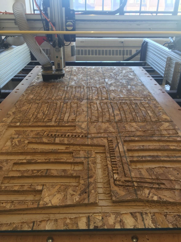
When laying out parts, leave enough space to make sure the sheet doesn't pop out when cutting. I also found it very helpful to lay drill holes in VCarve and having the router drill on specific locations, instead of drilling manually. This is especially important when you want to drill screws between parts in addition to the corners of the sheet.
Even though I had added tabs, some parts popped out regardless. Next time, I would make my tabs larger than 3"x3". You can also make square shaped tabs which hold better than ramped tabs (there is an option for both in VCarve).
To prevent losing parts, you can stop the machine and add screws in places that look like are about to pop out. You need to have a fast reaction rate to stop the machine when this happens. In one case, the mill head got stuck when jogging over a popped up part:
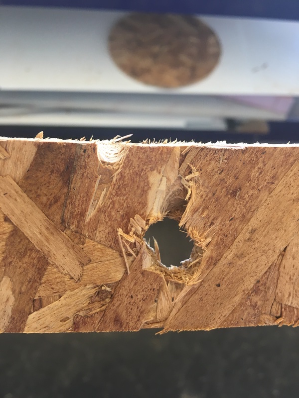
I had to stop the machine and take out the part. Then I moved it back to orgigin and visually checked to see if it's the same origin as before and restared a new job containing the pieces that were left.
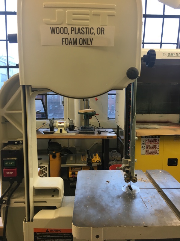
Another piece popped out when the machine was milling a joint. I used a band saw to manually make that joint.
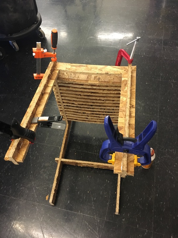
I glued down the joints that were loose with wood glue. You have to clamp the glued pieces for 20-30 min, otherwise gluing is of no use!
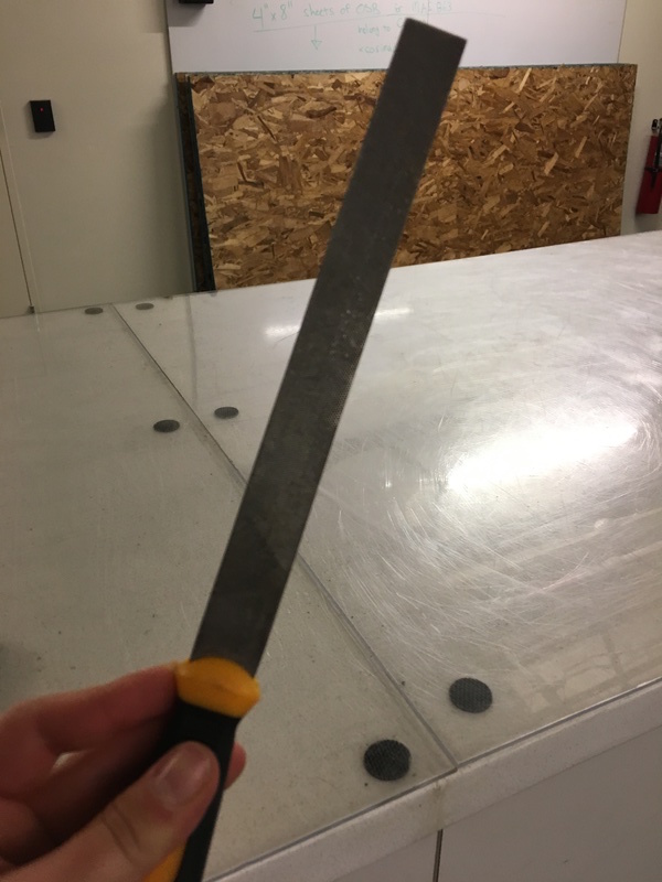
Lastly, I made the edges smoother with a filer and sand paper. OSB is a very cheap material and falls apart regardless though...