This week we worked on computer-controlled cutting - basically, using a 4'x8' giant sheet of OSB to produce something interesting and big. I decided to design another chair (I love making chairs). Here are some things I learned this week when using the CNC router in N52:
- Drill the edges of the board down to the sacrificial surface and make sure everything is stable and in place on the printing bed
- Load your design (pdf, or svg) into the vector->toolpath converting software.
- Choose each geometry, apply the right toolpath and drill settings to it (for example, pocket drilling vs. profile, and tabbing and depth) and add it to the list of toolpaths
- Reorder toolpaths so that small parts that are nested in other larger parts are cut first (makes cutting more stable)
- Select all toolpaths and export the print as an .spb (this is readable by the printer driver)
- Set up the printer by zeroing it on all axes - this means choosing the origin x, and y and running the printer job that zeroes it for the z axis (using cap. sensing to detect a metal surface you place under the drill) ** make sure that you remove the surface and the clip after zeroing (I didn't, and it broke part of the machine)
- Confirm that axes are zeroed (the z value should be 1 inch above 0)
- Make sure the shoe (the thing with the brushes that helps guide dirt to the vacuum) is connected
- Run the job in the air first, to check that it seems correct and isnt running off the edge of the board
- Print!
- Vacuum the surrounding area to collect any leftover dust
- Take off the scrap, sand down your pieces and you're done!
I had many more failures than successes this week but I learned a lot in the process.
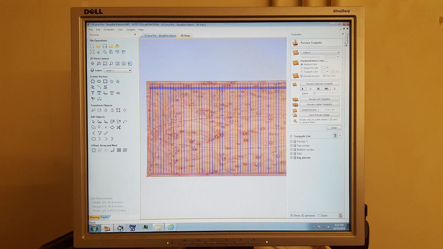
Loading the images into VCut here - nothing that hard, just make sure you choose the right units and the right dimensions when setting up your import. Here's what the software looks like (with a menu to adjust toolpaths on the right)
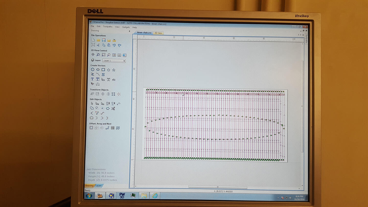
Here's what the toolpaths looked like after setting up the job.
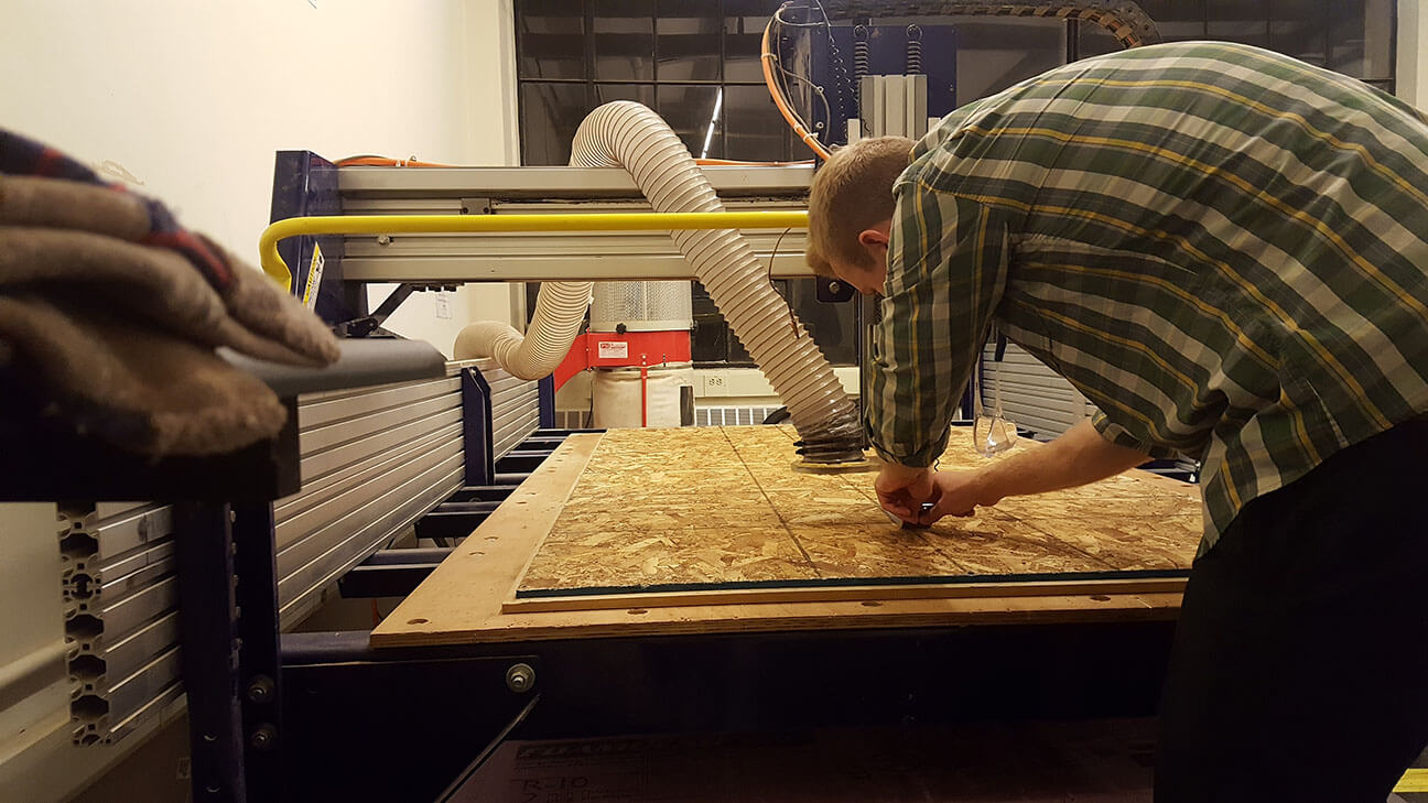
Now it's time to zero the printer head so that it's calibrated for the job. Here, Gavin is holding down a metal plate that the spindle will make contact with to complete a circuit using capacitive sensing, and find the origin for the z axis.
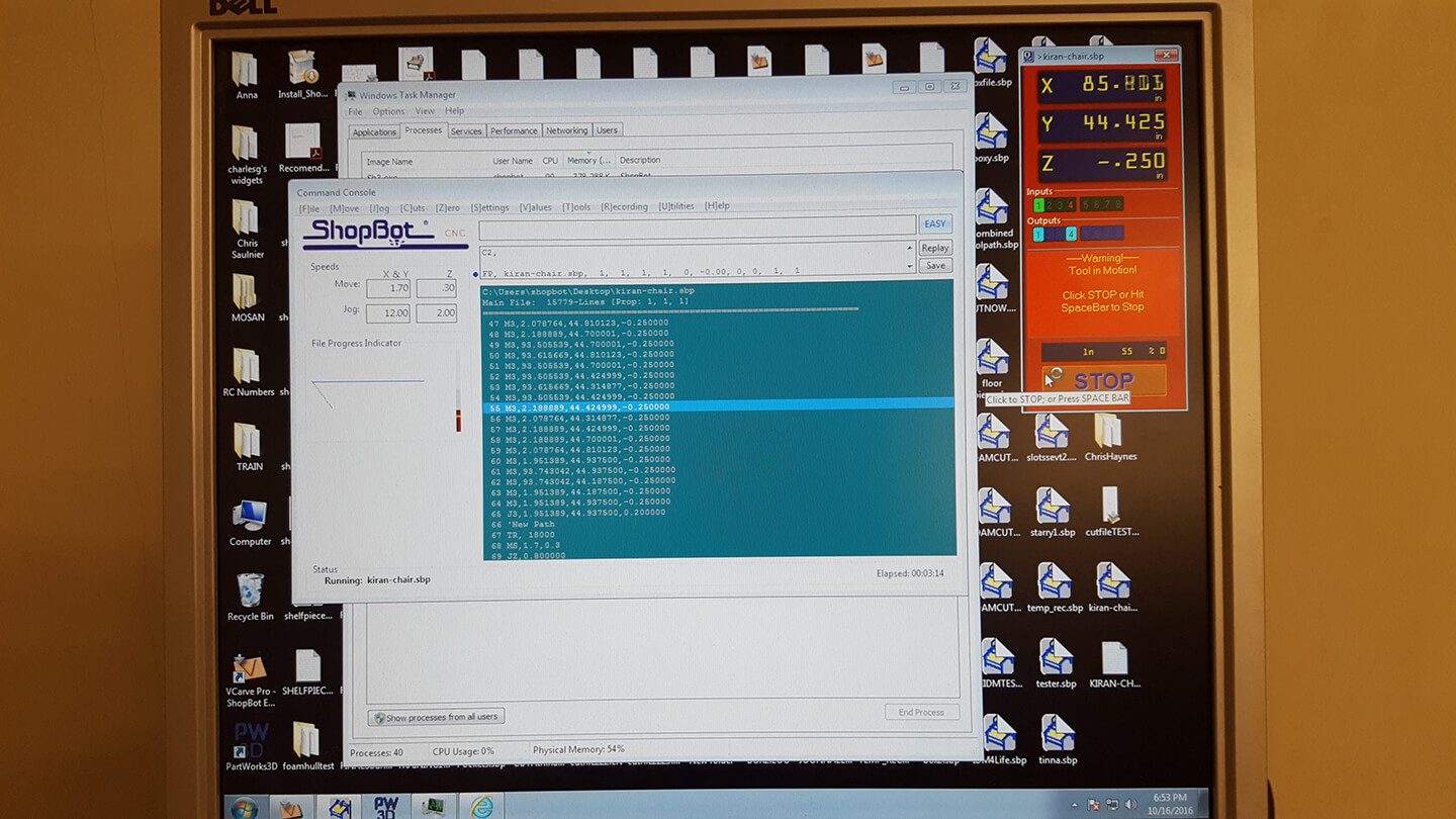
Here's what the printer software looks like for ShopBot. Its buggy and crashes sometimes but its nothing a forcequit and restart can't fix (Activity Monitor is pinned to the dock).
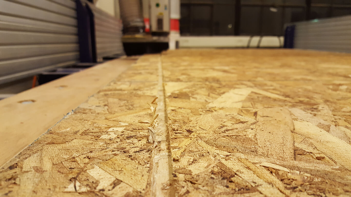
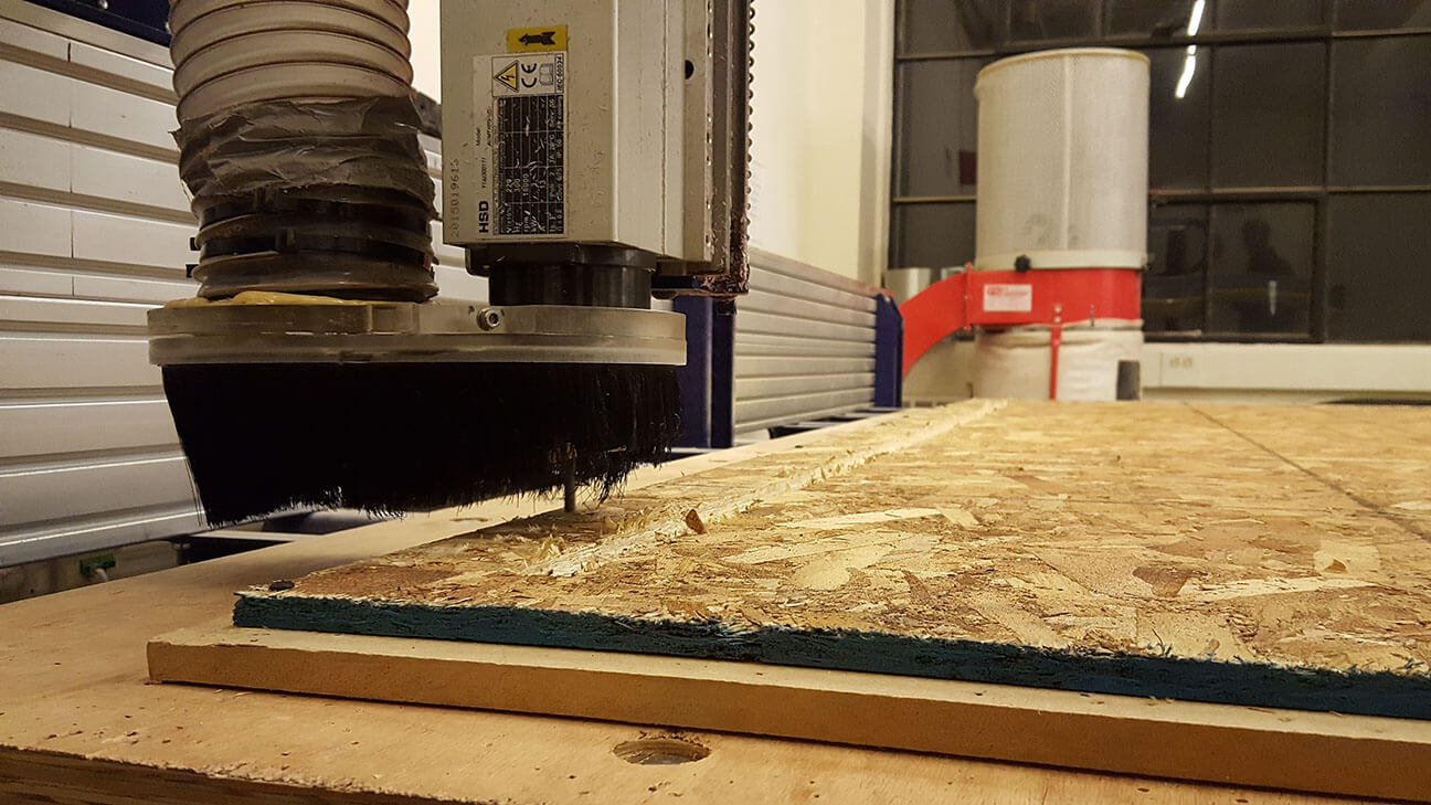
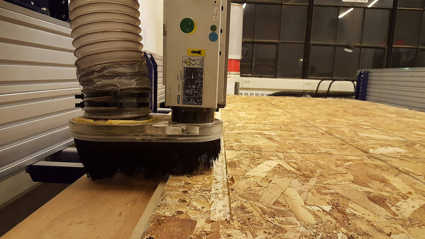
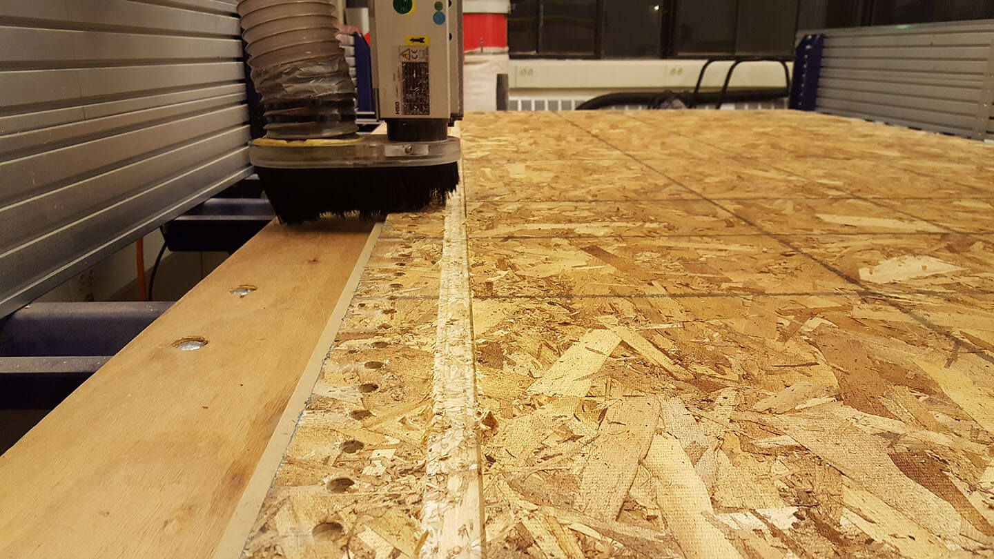
Here are some pictures of the job while it was running.
The first time I went in, I accidentally set the toolpath to only take 1 pass through the OSB, which caused it to be extremely unstable since there are a lot of small slats that are close together in my design.
The second time, I realized that the estimate for my job was 10+ hours because I had overlapping rectangles instead of lines in my design. I assumed that joining the geometries would cause the traces to be read as a single line but after importing, it looked like VCut saw each one as a separate shape and redundantly would cut each line. I also forgot to take off the clip for the Z-axis zeroing, which caused it to fly off the machine when starting the spindle. After this, and some design adjustments, the z-axis had an unexpected offset and the post-processing in VCuts toolpath export seemed to add lines that changed the machine's speed which would unreasonably slow it down. A lot of different things went wrong but I'm definitely more familiar with how everything works now and how to start debugging if something does go wrong.
**protips**
- OSB is not a consistently thick material - make a design that works well with this.
- If you have overlapping edges in your geometries, the toolpaths generated will not eliminate redundant paths. Make sure you eliminate these overlaps so that theres only one vector for each line you intend to cut.
- For some reason, VCut would post process the .spb with instructions that slowed the speed of the drill. We deleted these line by line so this wouldn't be executed when the job was running, but I'm not sure where they came from.
- Even after zeroing the Z-axis, the printer wouldn't cut all the way through and looked like it was cutting the air when it should have been cutting the material. What ended up happening was that there was an offset set in the z-axis on the printer before we got there, which altered our jobs. Printing in air to check that the job is right would not have revealed this until you actually start printing.
- Make sure you remove the alligator clip and the metal surface after zeroing!
- Make sure you put the shoe on the printer head - it's really easy to forget.
- Make sure you turn the vacuum on before starting the printer.
Unfortunately, I dont have anything to show for this week yet - Ill be going back into lab sometime to finish. Updates to come!