The Design Process
Attending the TA sessions and recitation was absolutely critical this week since I don't think I could have troubleshooted my way through Eagle nearly as quickly. I had an awkward time navigating the Eagle components library and workflow, though actually doing the schematic before wiring felt quite natural.
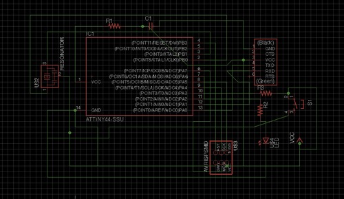
My completed Eagle schematic
It was not that difficult to create a traces image that did not have unwanted overlapping traces, but TA Tiffany did mention that next time, I should just name my components instead of drawing all the lines in the schematic diagram to make it easier to troubleshoot. That was the most time-consuming, as I did not want to mill the board and then sauter all the parts before realizing that my wiring was simply done incorrectly.
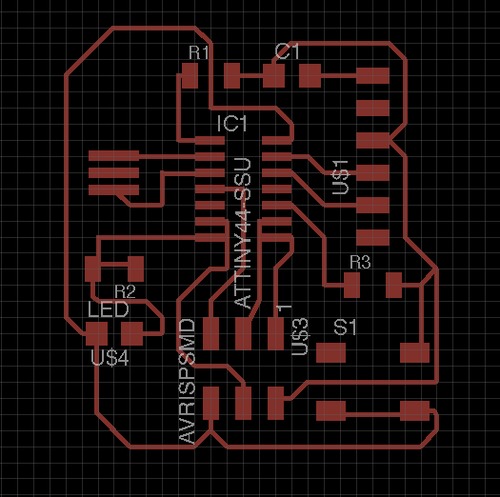
Connecting traces
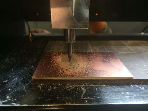
Beginning the milling process
During the milling process, I foolishly forgot to double check which size bit was left in the machine last, so I used the size meant for cutting the board outline, destroying my first attempt.
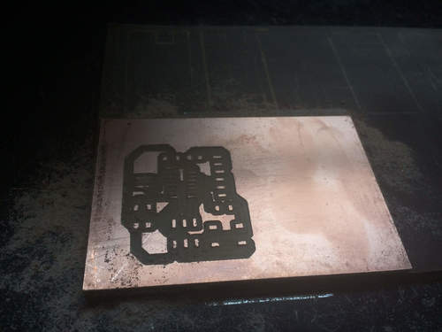
Ruined board!
Setting up to sauter
Once I milled the board, sautering was quite simple and went much quicker this time around. It was a challenge to sauter on the crystal, as it doesn't have clear legs but I was able to tin each pad, and then use the heat transfer of the sautering iron to secure the component in place.
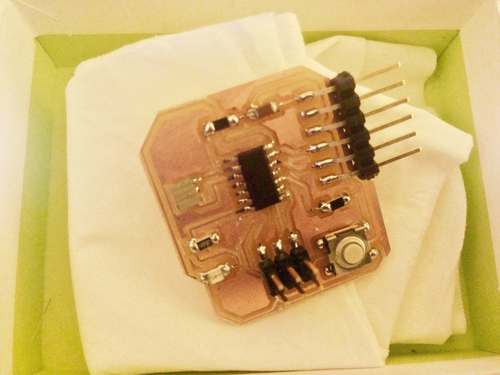
Completed working board
I tested the VCC and ground endpins on the board and received the correct voltage, and the computer was able to read the USB device without problem, so I believe my board is ready for programming!