The Design Process
When I plugged the programmer and my PCB board in, I was sadly greeted with error messages, where my computer didn't read the chip at all. So, it was back to the drawing board. With TA Tiffany Cheng's help, we were able to locate a few problems: The header was not connected to the attiny, and the milling job was not cleanly done, so the two pins on the lower left were actually connected together. I tried valiantly to fix the mistakes by sautering wires, but no luck! I then found out that there were problems with the way the ground line was traced around the board.
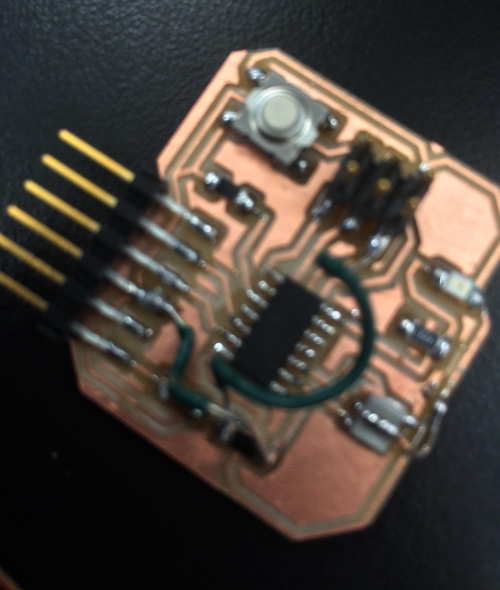
My failed chip and my sad attempts to use wires to fix it!
So, I went back to GIMP, and decided it would be faster to draw the traces correctly through GIMP than redo the whole board through Eagle. Once I remilled the board, I was extra careful to sauter the components accurately, as I definitely didn't want to make a 3rd board!
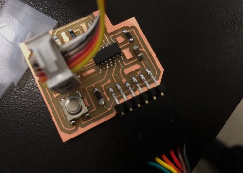
The new chip after I re-sautered the chip
This time, despite my careful sautering, the ground trace was so thin that sauter connected it to the pin on one of the headers. I used the heat gun for the first time and removed the chip and then used an Xacto knife to carve a trough to separate the traces. Whew - that worked!
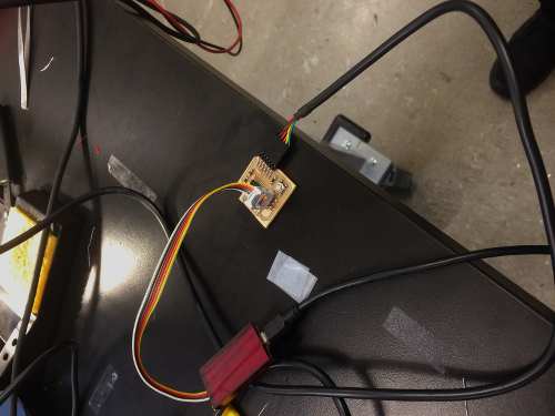
Everything all connected, and it all works!
This was the code I used:
#include #define F_CPU 1e6
#include #define TRUE 1
#define FALSE 0
int main()
{
//SETUP
//Button is on PA3
//LED is PA7
PORTA= _BV(PA3); //Turn button pullup resistor on
DDRA = _BV(PA7); //Enable output on the LED pin
PORTA = _BV(PA7); //Turns LED on
//LOOP
while (TRUE)
{
if ((PINA & _BV(PA3))) //button is not pushed
{
PORTA = 0; //turn LED off
}
else
{
PORTA = _BV(PA7); //turn LED on
_delay_ms(1000);
PORTA = 0;
_delay_ms(1000);
}
}
}