The Design Process
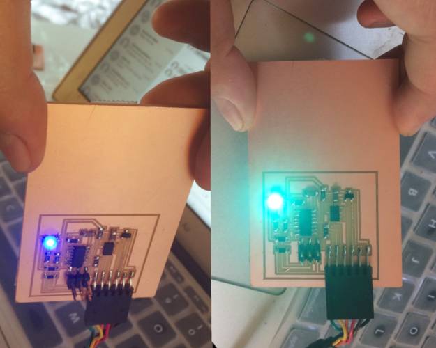
Once I had a board...finally...that was milled correctly, I went ahead and made another since I was fairly sure I would need another to practice soldering the accelerometer. I used the reflow method and the microscope to tin both the pads and the accelerometer. Then, with the heat gun, I hovered over the accelerometer for about ten seconds until the accelerometer gets "sucked" in by the flowing solder. It was actually very easy and I got it working on my first try. However, I realized I did not draw my traces correctly, and the accelerometer was not actually connected ot the microchip, so it was back to the milling process.
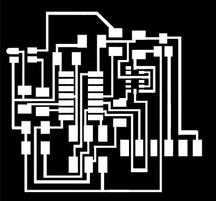
I used Photoshop to draw the traces
Creating the board png and milling the traces was definitely the main source of labor this week, as during my troubleshooting process, it turned out that the regulator was not properly soldered to VCC, so of course, my computer did not recognize the board. Luckily, that was a 5 minute kind of mistake, and FINALLY I had a board that seemed like it could work, 12 hours later.
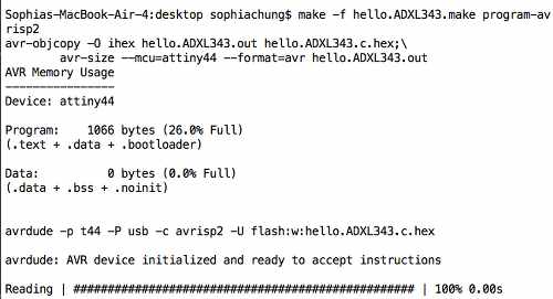
Documenting the lines of code I used to access the Terminal and program my board
Beginning to see some success
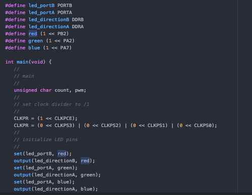
Next, I decided to test Neil's Hello World code for the RGB LED and the accelerometer separately, to make sure both were working. The first trouble came when I realized Neil's code was intended for the attiny45 and not the attiny44. For the RGB LED c file, I needed to edit the right pins that actually corresponded with my attiny44. That seemed easy enough until I realized that since the attiny44 used both PortA and PortB, I needed to create new variables, as shown in the picture below. Once I did that, things ran smoothly, and the LED worked exactly as planned!
To get the accelerometer working, it was a bit more complicated as it took me quite a while to figure out how the code worked, and what the numbers represented. But, once I carefully substituted the right pins on the attiny44, and downloded CoolTerm, I was able to see the hex code output!
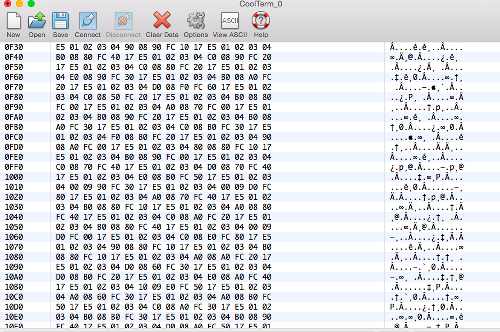
Hex code means the accelerometer was working
To combine the codes, I added the RGB code into the main while loop of the accelerometer code. To be honest, I sort of got it to change colors when I tilted the board, but the red LED does not work, and I don't completely understand what aspects of X, Y, and Z the accelerometer is controlling. Before I can continue using the accelerometer for my final project, I definitely need to understand the data sheet better. But, I feel quite proud of the progress made this week, given where I started. Plus, there was no more working on the computer, as I proceeded to become increasingly depressed regarding the dismal election results.
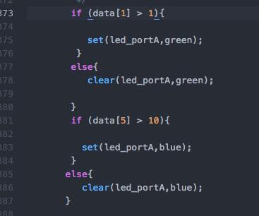
My edits to the accelerometer code