The Design Process
While time consuming, I do consider this week quite a success. I used Neil's Hello World acelerometer board to create the breakout board for my fabduino. Here, I faced some problems as I wasn't too confident about my electronics design knowledge to be sure I was doing the right thing. As soon as I plugged the accelerometer in, the chip burned extremely hot! Rob looked over my design, and suggested that I may have shorted out the chip. I removed the accleerometer and replaced it, and checked the voltage, especially across the regulator since I needed 3.3 volts. All went well! No more burning, and I was able to use the datasheet for the ADXL343 and ATTmega 328 to figure out how to connect the two baords together. SparkFun came in handy since they had a nifty explanation for each pin that was a little easier to understand.
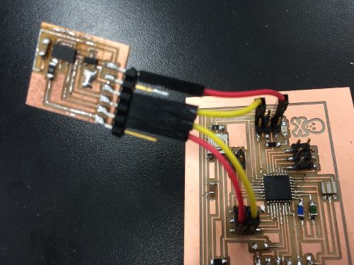
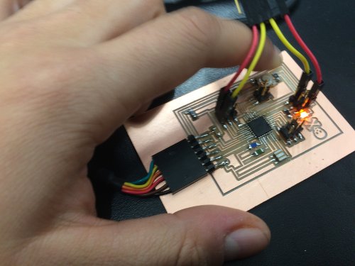
Everything all connected...finally!
To be honest, I can't really remember why it took so long to get the code working. But a lot of it had to do with troubleshooting the Arduino libraries. Despite following the instructions exactly, the accelerometer code would need a library that wasn't mentioned in the instructions. Or, the code was outdated, and I needed to revise some of the commands. Or, there were compatibility issues between different versions of Arduino. It was sort of a mess, but eventually, with some ediitng, I got the code to work! First I tested the basic blink code to make sure the fabduino was indeed working
Success - basic blink Arduino code
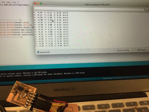
Then, I uploaded the accelerometer test code, which measure the serial output in a range from -10.00 to 10.00. Each output line has an x, y, z value, which is exactly what I need to input into a Max MSP patch for processing.
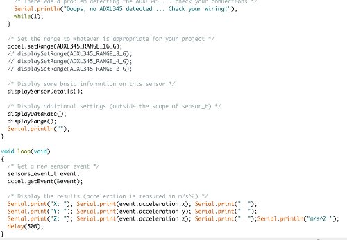
A snapshot of the code
As for next steps, I am currently researching how MAX MSP works, and how I can get it to read the serial data coming from the output. Ideally, I can set an if statement in MAX, that asks the program to pull a particular sound track when the values are within a certain range.