The Design Process
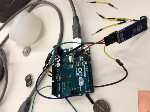
I started by testing out the HC-05 bluetooth module with the Arduino Uno. VCC needs to be connected to 3.3V, ground to ground, TX to RX, and RX to TX. My Mac was having a stupidly hard time with bluetooth devices, so it took me some time to reset bluetooth altogether (Shift+Option+bluetoothIcon) and then finally, I was able to pair the HC-05 and my computer (password: 1234). Then, I loaded a basic Arduino code that tells the LED light to turn on when I press a, and off when I press b. This worked fine, so I headed off to the next step - using my fabduino and accelerometer.
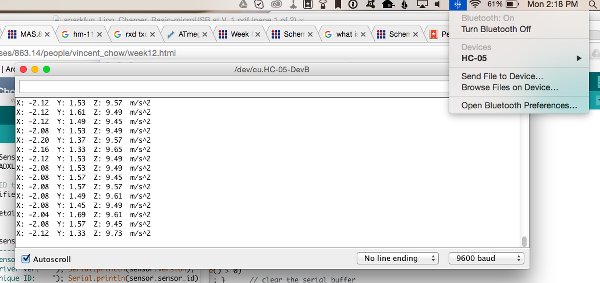
First running some tests through Arduino
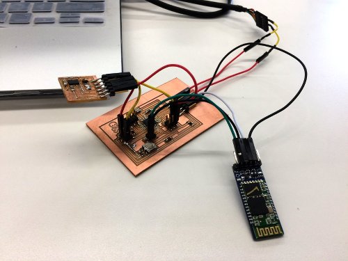
Everything all connected!
This step actually took quite some time, due to the amount of troubleshooting I had to do. Since I last worked on my fabduino, some of the traces had come off, especially the traces connecting to VCC. So, I gingerly took a piece of tiny wire and soldered that onto my board, which thankfully fixed the problem (you know there's a short when your computer kicks the USB device off for drawing too much power)! Then, I faced other troubles figuring out how to connect all the pins. Basically, I tried to run the LED code to no avail. I'm still not sure what I did wrong, but for the sake of time, I decided to proceed with the accelerometer. More mishaps happened when I realized I switched the RX and TX pins, and realized that the program in Arduino needs to be loaded with the FTDI cable. Then, once it is uploaded, connect TX and RX of the bluetooth module to pins 4 & 5 (TX and RX) of the FTDI, and then pair with the computer. Whew! Finally, everything worked on Arduino. But when I connected to Max MSP, I was getting errors again. Running Max would consistently kick off the bluetooth module after 10 seconds or so. I'm stil not sure I fully understand why, but I figured out that Max was labelling the serial port differently when using bluetooth rather than FTDI cable. When I switched port c to d in the patch, all went well!