
Week 3: 3D Printing
I use 3D printing quite a bit in my research lab and I decided to learn more about the properties of the 3D prints. In particular, I was curious about the anisotropy of the prints due to the direction of extrusion.
In FDM printing the adhesion of the print layers is of particular concern. Instead of depending on the bulk strength of the material, the strength of the print in the axis of extrusion depends on the strength of the bonds between layers.
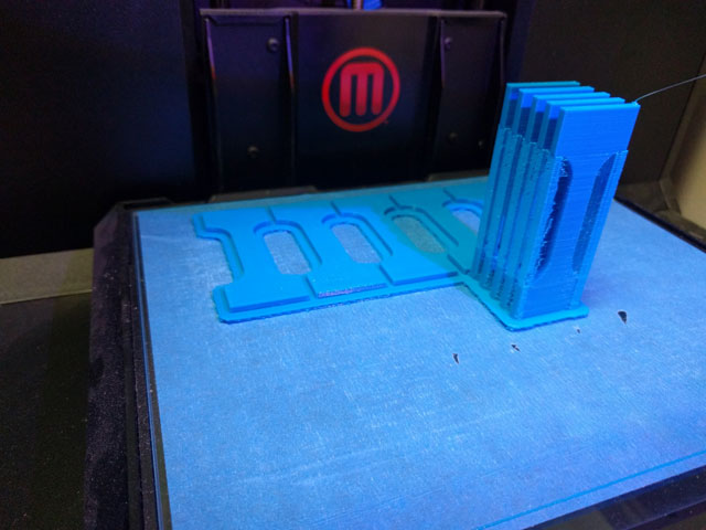 MakerBot prints in both the XY-axis (left) and Z-axis (right).
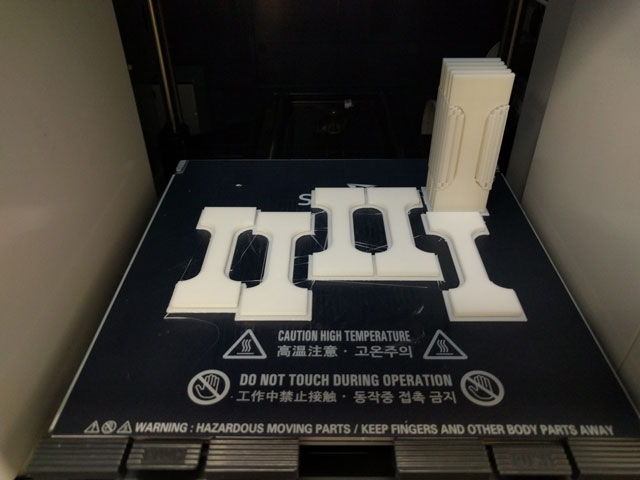 Sindoh prints in both the XY-axis (left) and Z-axis (right).
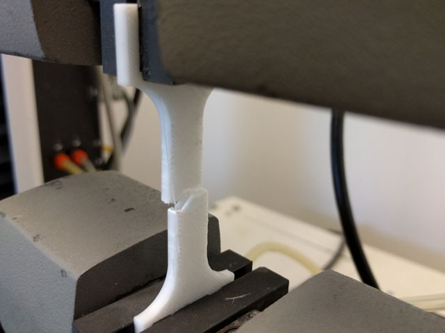
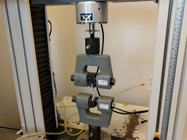 Dogbone test piece in instron instrument.
At my lab I have access to an Instron materials characterization machine (similar to this one). It uses motors to move a clamp holding the specimen and uses a load cell to measure the resultant force.
The test shapes used resemble dogbones because the grips can deform the material in undesirable ways and cause failure at the grip rather than in the material. To counteract this, the material is wider at the grips to distribute the load more evenly and concentrate the stress in the center of the material.
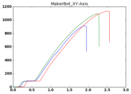 MakerBot PLA Force vs Extention Testing when the vertical print axis is perpendicular to the testing axis.
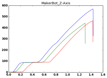 MakerBot PLA Force vs Extention Testing when the vertical print axis is parallel to the testing axis.
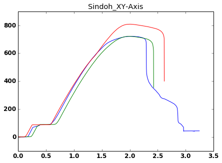 Sindoh PLA Force vs Extention Testing when the vertical print axis is perpendicular to the testing axis.
Note the creep failure of the material as opposed to a clean fracture.
Sindoh PLA Force vs Extention Testing when the vertical print axis is perpendicular to the testing axis.
Note the creep failure of the material as opposed to a clean fracture.
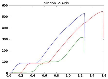 Sindoh PLA Force vs Extention Testing when the vertical print axis is parallel to the testing axis.
| Test | Average Elastic Modulus (MPa) |
|---|---|
| Makerbot XY | 660 |
| Makerbot Z | 520 |
| Sindoh XY | 576 |
| Sindoh Z | 556 |
The elastic modulus of the PLA was pretty consistent across all the tests however, the ultimate tensile strength varied greatly. The Z-Axis tests both delaminated much earlier than the XY tests (50% on the Makerbot, 75% on the Sindoh). Furthermore, all the tests had breaks that occured on layer or material boundaries rather than in the bulk material.
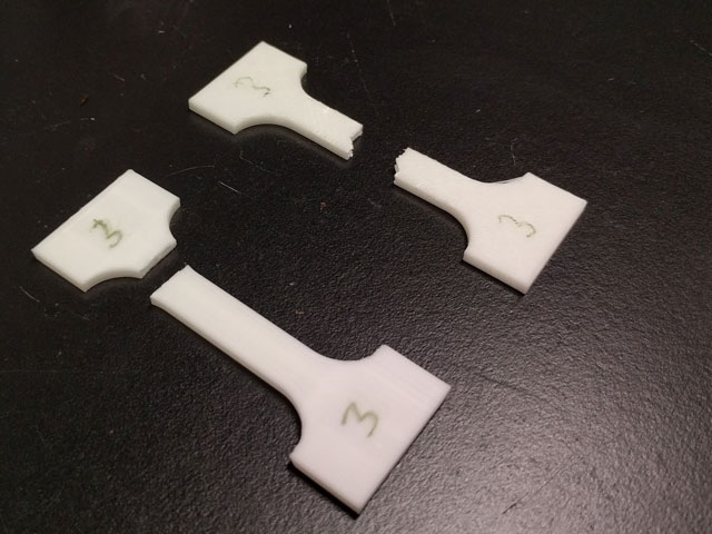 The bottom break occured on a Z-Axis print and cleanly delaminated. The top print
occured in an XY-Axis print and also occured on a boundary but not in the direction of printing.
The bottom break occured on a Z-Axis print and cleanly delaminated. The top print
occured in an XY-Axis print and also occured on a boundary but not in the direction of printing.
 Another angle on the XY break showing that the break occured along a infill boundary as opposed to
in a continuous fiber.
Another angle on the XY break showing that the break occured along a infill boundary as opposed to
in a continuous fiber.
Continuing my interest in creating more flexible materials, I thought I'd print some springs and see how they turned out. The end goal was to make a 2-axis stage that could be used for imaging or placing.
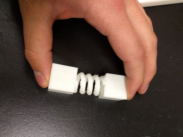 First example piece of a spring between two blocks.
I ran into some problems with the raft/support adhearing too well to the coils that made the springs which ended up destroying the entire print. After some careful work to remove the raft and support materials I was able to get a working piece. However, in the future, I eschew the helical spring in favor of 2D flextures.
Once again, I encounted the anisotropy of 3D printing when printing the springs. The springs printed along the Z axis were generally stiffer than those in the XY. They also seemed to be somewhat stronger than the XY direction. I didn't have time to characterize this on the instron, but would like to in the future. However, since the stage needed to be consistent in all directions, the stage was printed in the XY direction.
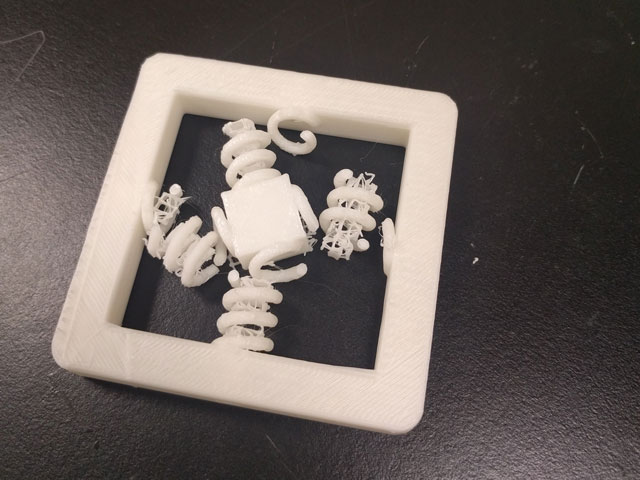 Unfortunate results occur when I'm impatient and the raft is stuck too well to the coils.
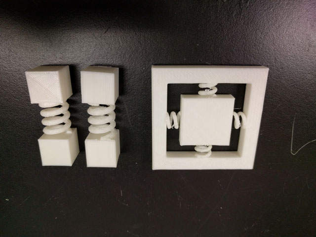 Final completed designs. The two spring tests printed in different directions to determine the optimal
direction for support. The stage at right does deflect in two dimensions, although not as much as I would hope.
Final completed designs. The two spring tests printed in different directions to determine the optimal
direction for support. The stage at right does deflect in two dimensions, although not as much as I would hope.
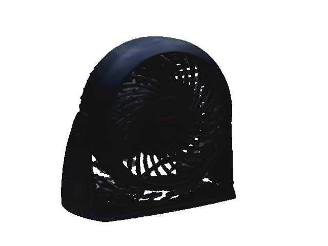 Scan of a fan from the Harvard Lab. I chose this object due to its complex geometry.
I tried the Sense 3D scanner at the Harvard Lab but it suffered from quite a few crashes I never got the software to scan for longer than two minutes without a crash so my scan was limited to what was easy to manipulate.
I was pretty impressed with the results for such a complex geometry. However, I wasn't able to get any results with anything smaller than 10 cms square or larger than 50 cm square which limited its utility. If I had more time with less buggy software, I'd be inclined to get a full setup and try to modify a file for reprinting. For now, I much prefer using calipers and micrometers to reproduce objects.