
Week 4: Electronics
As an electrical engineer, I've done a fair number of simple circuits and boards. This summer, I transitioned from Eagle to Altium's CircuitMaker as my main EDA tool. I've generally found it to be more powerful and more similar to my idea of an ideal workflow.
I thought that it would be worthwhile to use CircuitMaker for HTM[A]A as I am still getting used to it. This required a little more involvement than simply importing the EAGLE library file and laying out the board.
Instead of library files like Altium Designer or Eagle, CircuitMaker uses a single crowdsources library. I found most of the parts easily. The 20MHz resonator, SMT Header, and resistors all came with premade footprints. The FTDI header did not so I had to go into CircuitMaker's editing tools and make my own footprint. After about 10 minutes of transfering the measurements from the Hello World board, I created a public FTDI header footprint (FTDI-SMD-HEADER) identical to the one in the EAGLE file.
After making the component and laying out the board, routing proceeded normally. However, I had to modify the default design rules to support the tooling used (trace to trace spacing of no less than 1/64"). After some fiddling I was able to add the button and LED without too much trouble.
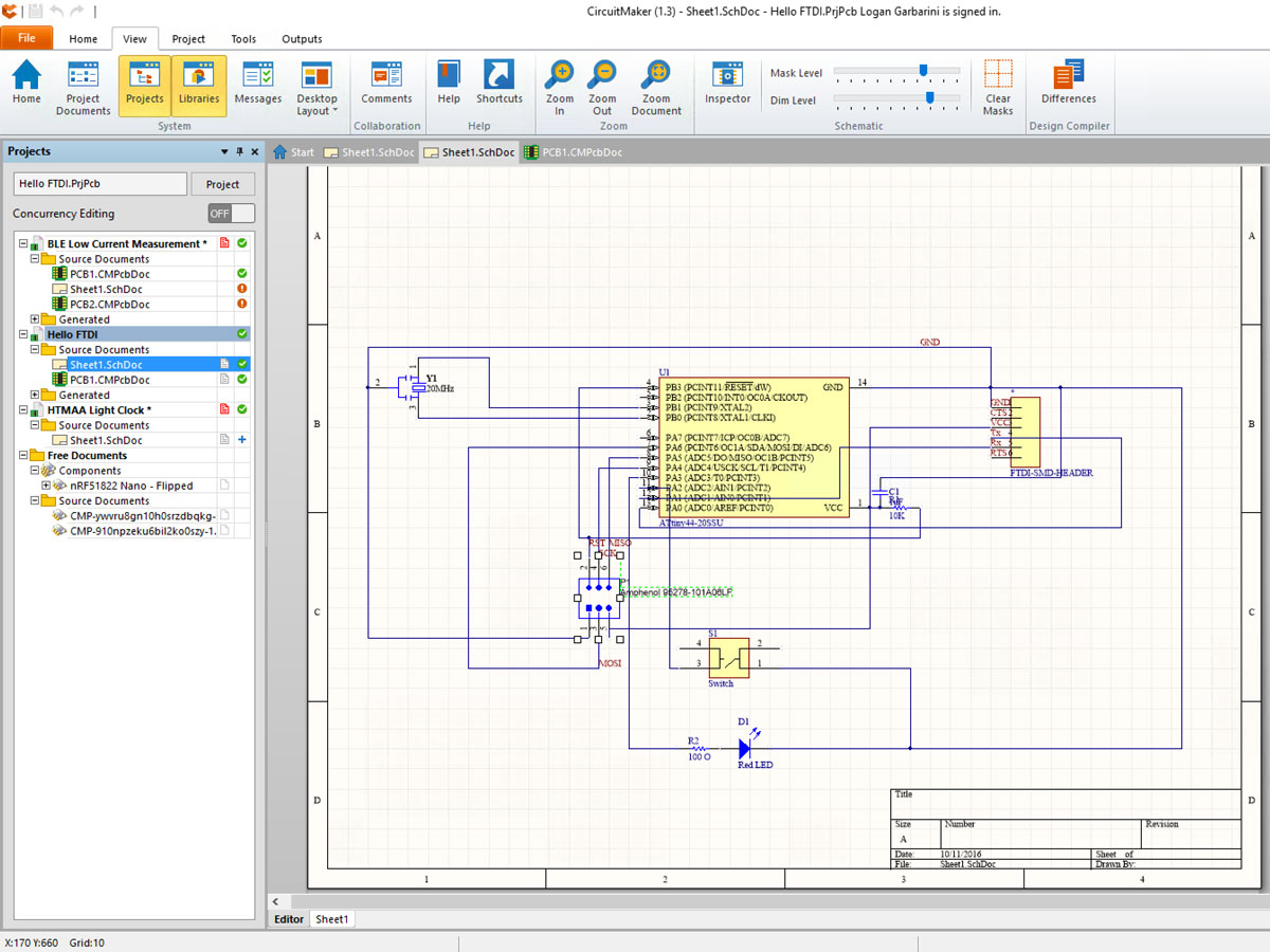 Messy schematic for the Hello World board.
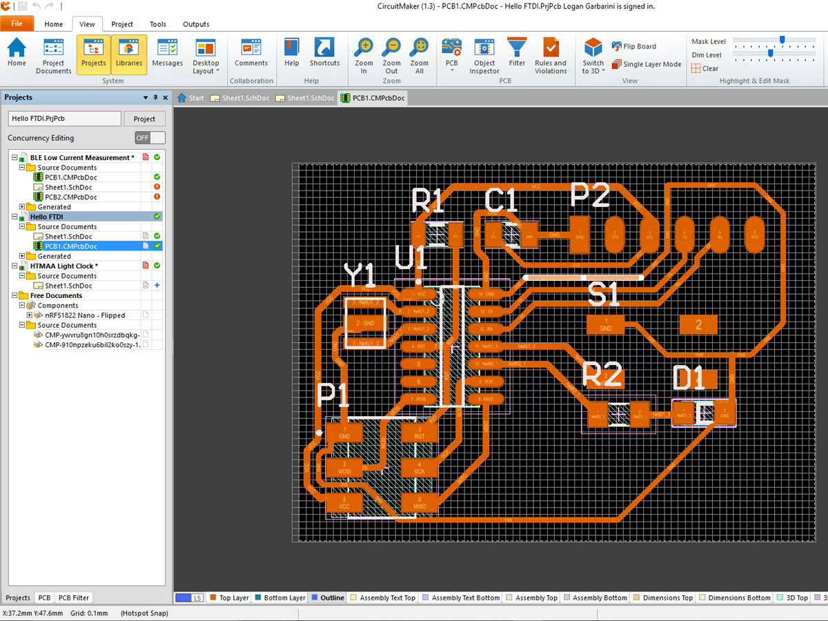 I spent a little more time organizing the board layout which, other than
some unused space came out nicely. Note the blue outline line which is
used make the outline file later.
I spent a little more time organizing the board layout which, other than
some unused space came out nicely. Note the blue outline line which is
used make the outline file later.
I've used LPKF circuit milling machines before this class and these take Gerber files. Just in case I threw one of the FR1 boards onto the LPKF mill and milled the board there. However, I still wanted to mill using fab modules! After a little Googling, I found Gerbv, an Open Source tool to view and manipulate Gerber files. One of the outputs it could do was PNG. After exporting, Fab Modules happily accepted the file and milled it.
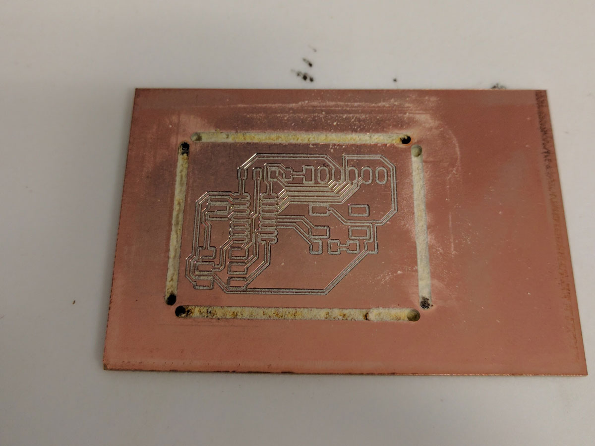 Board Milled with the LPKF Protomat S103 in case I didn't get the PNG
export to work.
Board Milled with the LPKF Protomat S103 in case I didn't get the PNG
export to work.
CircuitMaker generates a Gerber file for each layer. In order to process the Gerbers into PNGs I figured out two lines commands.
The first line takes in both files and sets the export type to png (-x png), then it specifies the output file (-o brd.png), then sets the DPI (-D 1200), then specifies the background color (-b #FFFFFF), and foreground color (-f#000000).
The second line does the same but just with the outline file.
Then I had to import them into GIMP/Photoshop to fill everything outside the outline line as black and delete the outline line itself.
Once I imported the PNG into Fab Modules I was able to mill the board. It almost turned out perfectly except I forgot to change the DPI on the second run which left a large cut on the board. Instead I just used LPKF board. However in the future, it's easy to use Fab Modules.
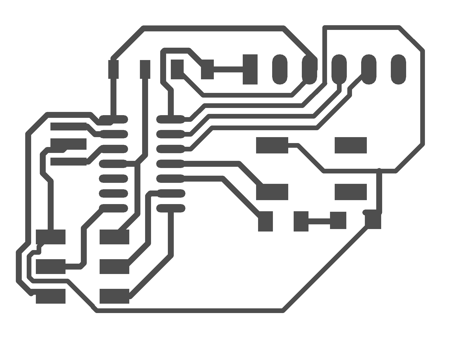 After a few processing steps, I can turn CircuitMaker Gerbers into fully
supported PNGs for milling by fab modules. Above is the traces for the board.
After a few processing steps, I can turn CircuitMaker Gerbers into fully
supported PNGs for milling by fab modules. Above is the traces for the board.
 And the outline for the board.
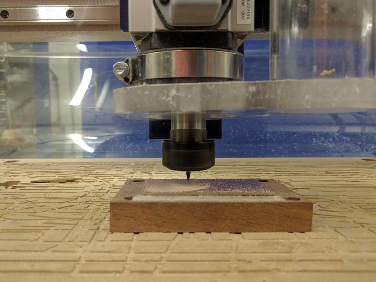 Milling the board using FabModules.
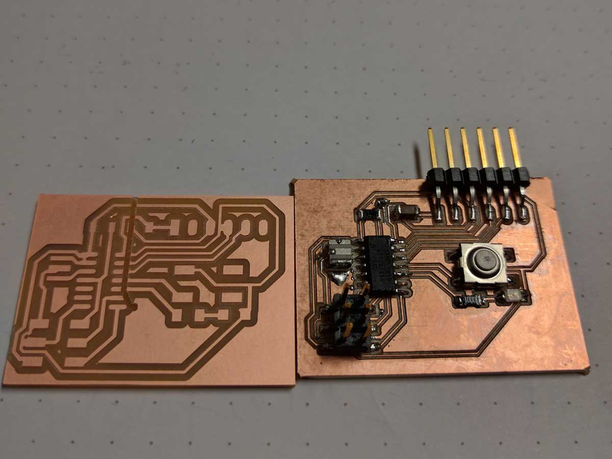 The Fab Modules board to the left of the LPKF milled board. I was going
to assemble the Fab Modules board, but I forgot to adjust the DPI
correctly which led to the accidental cut through the entire board.
The Fab Modules board to the left of the LPKF milled board. I was going
to assemble the Fab Modules board, but I forgot to adjust the DPI
correctly which led to the accidental cut through the entire board.
After that, Soldering went very smoothly without much of a problem. One thing I have noticed and did encounter with CircuitMaker is that since the components library is crowdsources some footprints don't follow the official standards for pad size. I had a few pads that were a little too small for my liking.
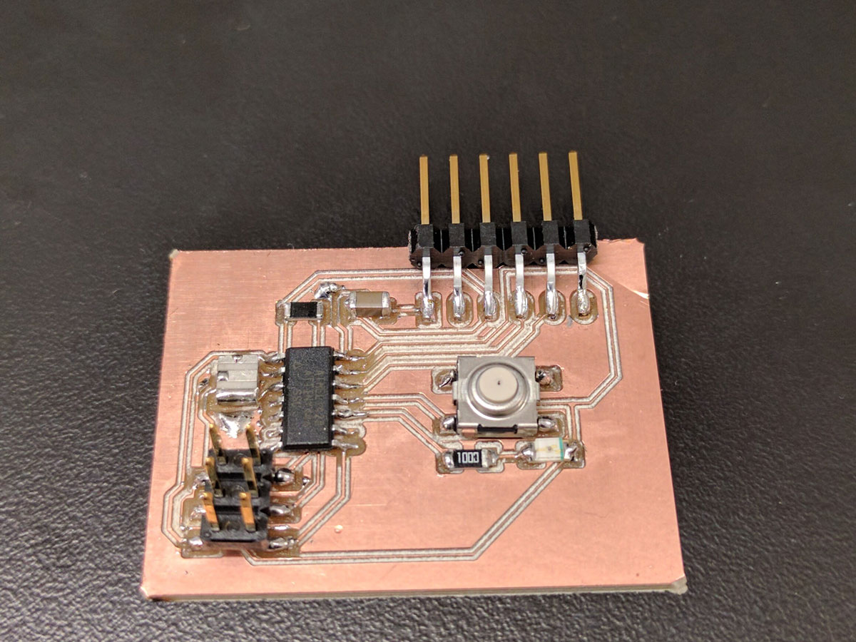 The assembled board.
Similarly, programming the board went smoothly. After plugging in my FabISP the right way, the make script detected my board without any hiccups. I used the Arduino Serial Monitor to test the board and it seemed to work just fine.
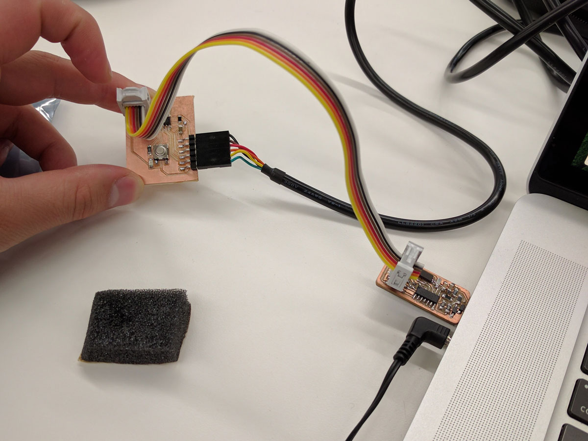 The board being programmed with my FabISP.
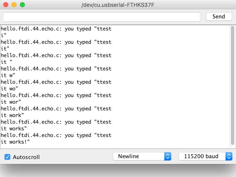 The programmed board responding to serial communication.
I started working on a second board design with MOSFETs for power control I have a RGBW LED strip at home that I'd love to control programatically. Specifically, I want it to change the color and brightness of light as the time changes (think F.lux for your house).
As the TINY44 doesn't have quite enough IO for my liking, my design involves the XMEGA. I will update this page when I get around finishing the design.