Week Five: Hello World Chip
There’s making Hardware, and there’s making it interact with you!
Background
For this week’s assignment we started our own board design. The goal was to replicate the Echo Hello World Board: A simple board with an ATtiny, an FTDI interface, capacitor for GND, and a pull-up resistor for ResetN. We were asked to add some components such as LEDs and/or Push buttons.
Eagle, Board Design
I’ve always designed and simulated with Spice, so Eagle was new to me. As a first step I created the schematics for the board, and added a few features:
-
A button with a pull-up resistor (default input value for the pin will be
1, when pushed will be0) -
An LED connected to an output pin.
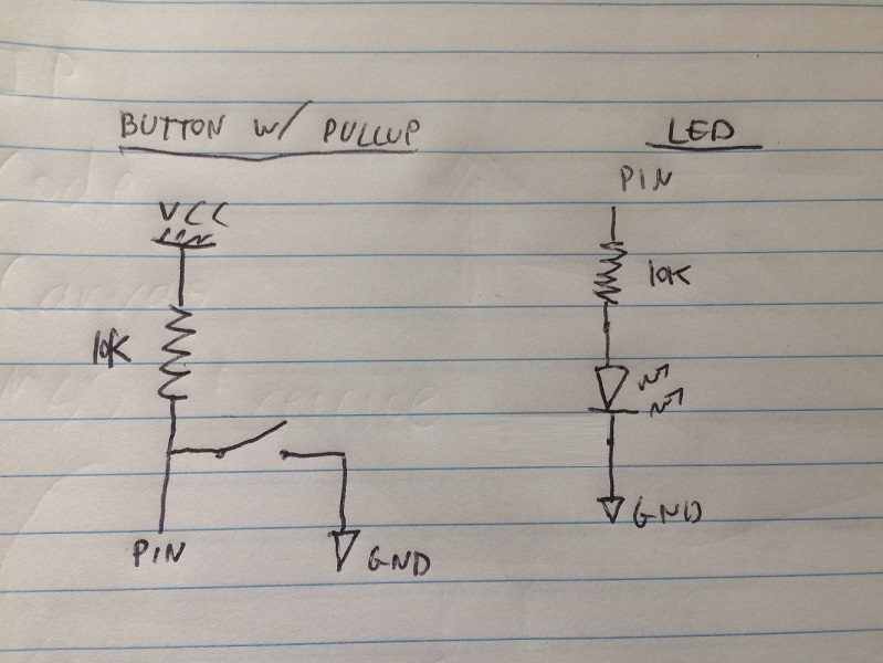
Here’s a sketch of the extra parts added:
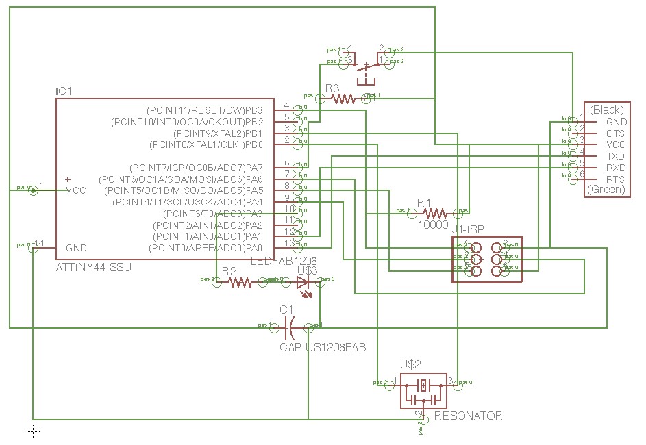
And here’s a screenshot of the Eagle schematic:
As one can see, this is a bit messy! Wires on top of each other is not something that will work for us while using the Modela. So moving on to the Board design itself:
- Added a ruler. Why? No real reason. Because it’s cool.
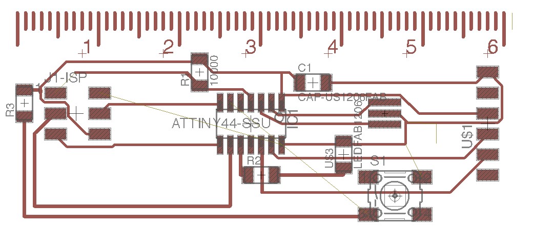
- Shifted the components around to try to get it all into a 2D layout. This was the best the AutoRouter could come up with (as we can see there are still some unrouted traces):
(There’s a mistake here! We’ll get to it later)
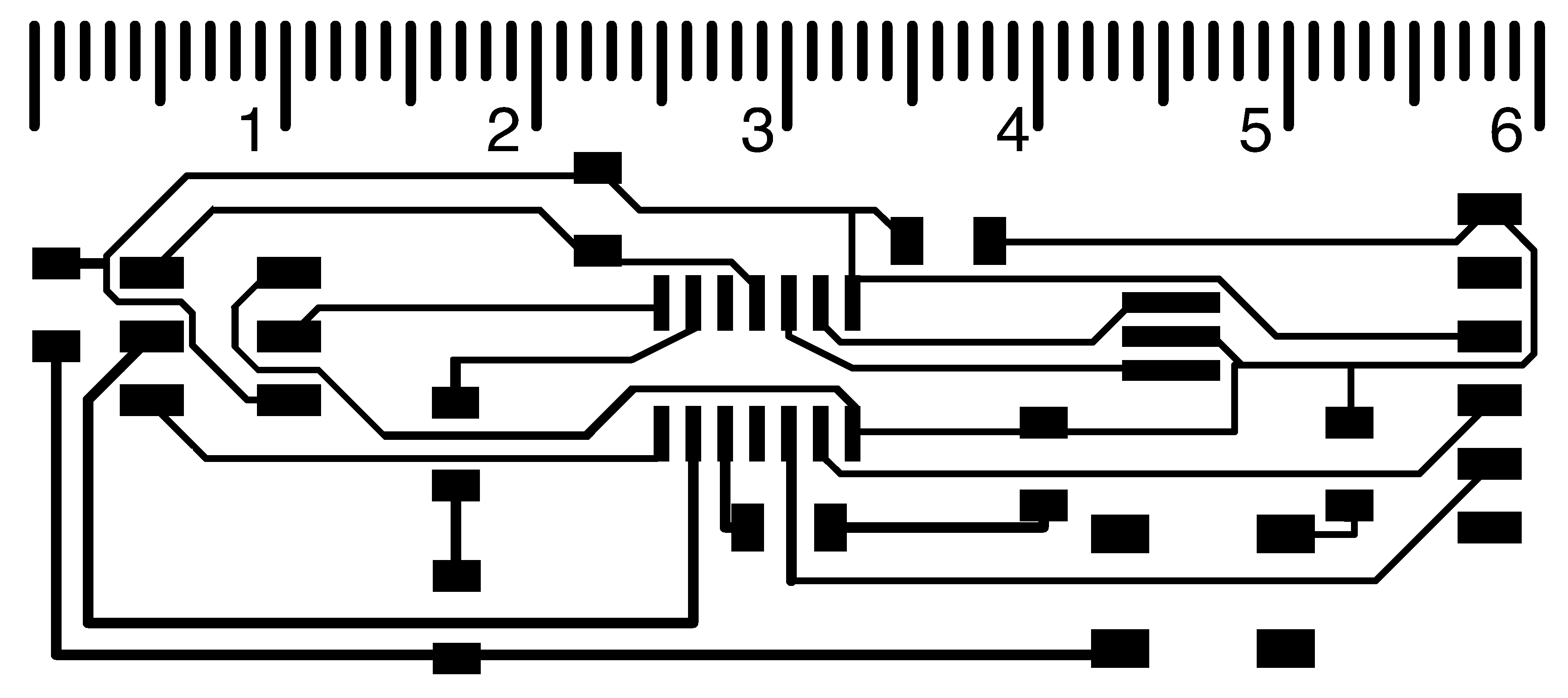
In order to wire the traces that are unrouted, I realized I would have to either reposition everything, or use some 0-Ohm resistors as bridges. I chose the latter option. Eagle is pretty annoying here - putting a zero ohm resistor, even though it is only a Board consideration, requires going back to the schematics. So I gave up on Eagle, exported what I had so far to an image, and added the 0-Ohm resistors in my favorite Image editor. Here’s the result:
(There’s still a mistake here! We’ll get to it later)
Here’s a link to the outline png.
Millin’!
Here are a few takeaways from the Modela process:
- People always leave the Modela with the outline bit on. Make sure to change before you run the traces!
- Modela likes white on black, not black on white (think of it this way: Modela etches what will not be conductive). So make sure you invert the image before running!
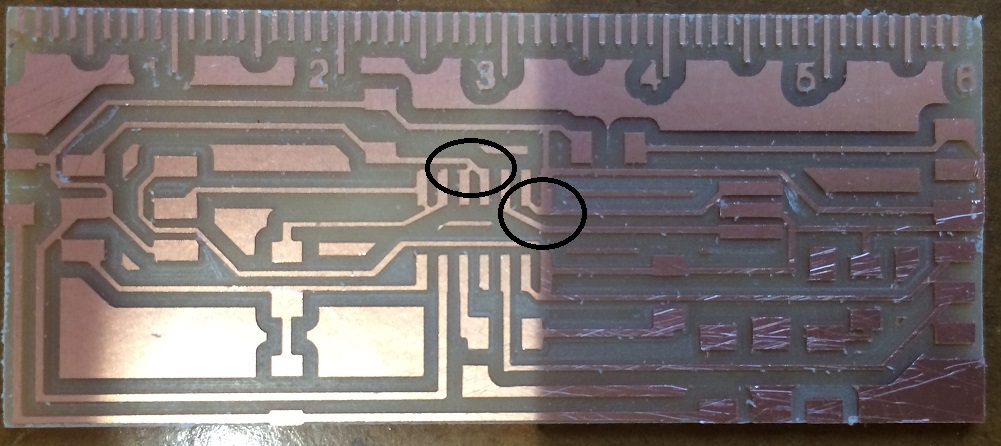
- Some delicate areas (see with a black circle below) were not milled properly because of the resolution. That’s not a problem though - a small cut with an exacto-knife to separate the pieces does the trick. Just remember to check with a voltmeter that the two separate parts are indeed not short-circuited.
Soldering
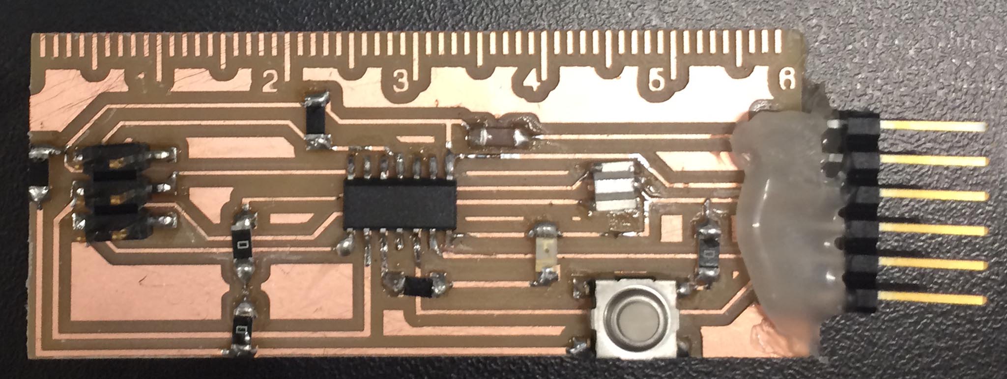
No real issues here, pretty straight forward. Just remember to check with a voltmeter that the two separate parts are indeed not short-circuited (this is especially important when using 0-Ohm resistors as bridges). I applied a generous layer of hot glue (insulating material) to make the FTDI interface stronger.
The biggest mistake I’ve made yet!
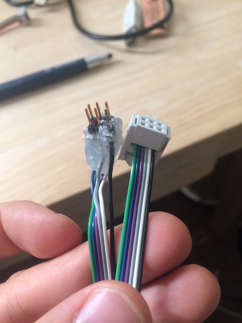
Just as I was about to connect my FabISP to the Hello World chip, I noticed a HUGE mistake. I connected the wires on the 2-by-3 in a mirrored way. Meaning, if we look at this original schematic we see that VCC can be either on the bottom right, or, when ROTATED (not mirrored), on the top left. I accidently mirrored the wires and had it on the top right. Fixing this means redoing everything, and I wasn’t in the mood for that, so I made a female-to-male cable that mirrors the pins.
The soldering work here wasn’t perfect, and I also applied a generous layer of hot glue to protect it. At some point one of the pins broke, but I managed to replace just this one single pin from another connector. Ugly - but functional!
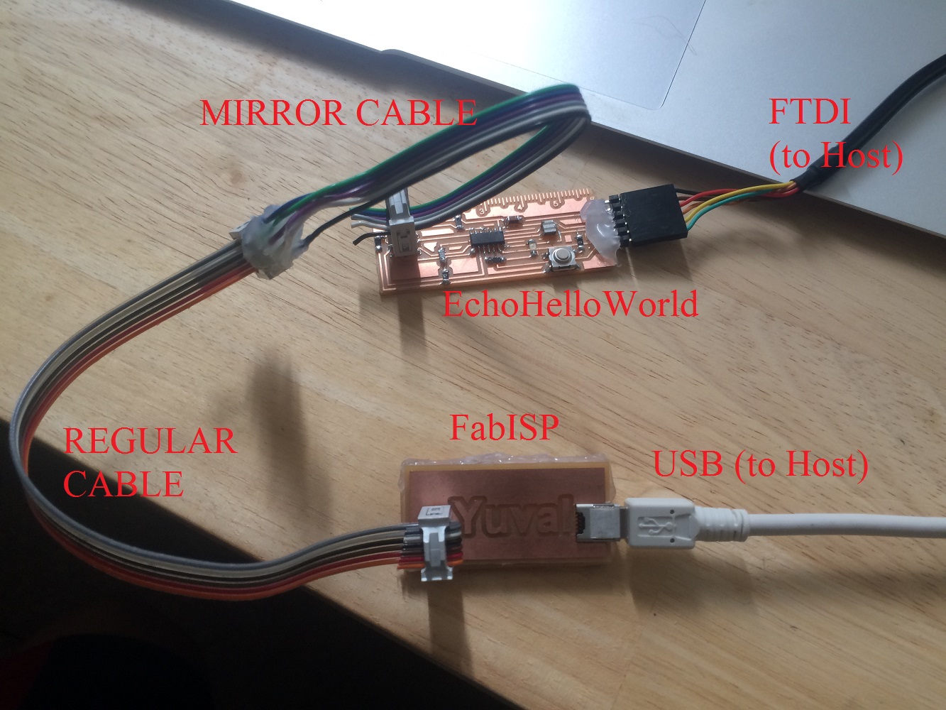
Here’s how the final setup looks like for programming:
Programming
I basically followed This tutorial which is fairly simple. Just have to remember to connect the cables in the right direction.
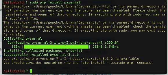
- Installing Pyserial on mac is just once command:
sudo pip install pyserial. (This may require some extra installations that I already have on my computer though):
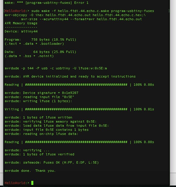
- Making the fuses:
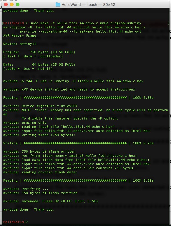
- Programming:
IT’S ALIVE, ALIVE!!!
After programming, we can disconnect the FabISP from the computer and work with the new board standalone. Here’s a video:

