
Week Two: Laser Etching and Cutting
We were asked to design, make, and document a parametric press-fit construction kit, accounting for the lasercutter kerf, which can be assembled in multiple ways.
Laser Cutter background
The laser cutter can do a bunch of things on different types of material, but more on that later. Today we will be using cardboard for etching and cutting.
How it works
The laser cutter has 3 main settings: Power, Speed and PPI (pulses per inch).
-
Power: As intuitive as it sounds: The high this number is, the more powerful the laser beam. Under a low setting we may only get some change in tone/color, while a higher power will cut through the material. Each material, of course, requires different settings for different outcomes.
-
Speed: Pretty simple too. I’m not sure what units this setting lives in, but you get it… Higher=faster, lower=slower.
-
PPI: This is some sort of “density” measure. if we are running a job at 1000 ppi — this means that the laser is pulsing 1000 times per linear inch of travel.
Laser cutters vary by wattage. I did most of the work this weekend on a 120 Watt machine.
The laser cutter is mounted on the OS like any other printer. Every time we send a file for printing, we change the printer settings to handle each color differently; for example, if it’s red - use power X, speed Y and ppi Z; if it’s blue - use A, B and C respectively, etc. Here’s a nice sheet the GSD has prepared for us with recommended settings:

Etching
When using a low power setting, the laser is strong enough to deform the color of the cardboard but doesn’t cut through it, a pretty cool technique to do interesting things. Etching works best with rastered images because it does not deal with lines, but rather with areas.
For the etching exercise I went on Google maps and dragged to locate map of Boston. I then used Adobe Photoshop to convert this map to a monochrome image - black and white. I then went back to Rhino (which is a high candidate for being the coolest software I’ve used yet) and imported the monochrome image, scaled it to the 18”x32” piece of cardboard, and printed it. A pretty cool result, even though my wife calls is a “fancy pizza cardboard”.
Original Image:

Monochrome conversion:

Imported to Rhino, scaled:

Machine in action:

Final Product (hard to photograph, tried my best…):

And a quick movie of the laser doing its thing:
Cutting
Technology-wise, cutting and etching operate on the same principles with different settings. For this project we needed to make a press-fit kit. Here are some thoughts in random order before moving on to what I actually made:
-
Kurf: The laser burns away a portion of material when it cuts through. This is known as the laser kerf. When designing press-fit mechanisms we have to account for that.
-
Parametric design is important: There is definitely trial and error associated with the cutter. Each material has its own characteristics, and for press-fit mechanisms, the cut has to be the exact width of the material. If we make our design file properly, we can change the width of the cut with one simple click for many cuts throughout the design.
-
Joints: As we learned in class (this Antimony model was made by Prof. Gershenfeld) there are several tactics to making joints, each with its own advantages and disadvantages. I ended up using the standard simple cut; for the cardboard we were provided in class it was sufficiently strong. Attempts to print the more “complex” joints sometimes resulted in joints that were more cumbersome to assemble.
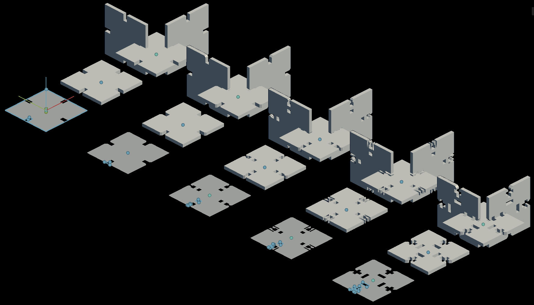
For cutting I decided to print several “puzzle” pieces in various shapes: Round, oval, rectangle and triangle, to try to let my imagination run (I still can’t think of a good idea for a final project). Weapon of choice for the start of the exercise was Inkscape. I chose it because (a) I haven’t used it yet, and (b) the parametric design with it is very simple.
Here’s an image of the pieces I created. The base cut line, on the top right, is the source and other cut lines are cloend from it. Changing the width of that line immediately changed the width for all others:


Next we have to make this image readable for the machine. Inkscape has a boolean difference tool (similar to what I used when making the holes int the 3d model last week), but I chose a different technique this time: I imported the file to Rhino and then used Rhino’s “trim” command to cut the excess sides. This is the end result:

I won’t lie - here that were some bad attempts to find the ultimate cut size for accounting for kerf, etc (measure once, cut 5 times… Eep.), but I ended up with a few cool puzzle pieces and build what can arguably be called a dog:

Using the same pieces I build what could even more arguably be called a submarine:

And here’s a cool video of the laser cutter in action: