
Week Thirteen: Networking
WiFi Web Server at your service.
Background
This week we learned about networking and communication, and were required to design and build a wired &/or wireless network connecting at least two processors.
ESP8266 WiFi
My weapon of choice for this week was the ESP8266 WiFi chip. I want to integrate this chip into my final project so that connectivity and instruction could be given remotely.
First attempt: Neil’s WiFi board with added pins
For my first attempt, I took Neil’s Hello World Board (Board Traces Cut) and updated it to add a few more basic features that I add to most boards I make: an LED and easy access to some GPIO pins. Details Below:
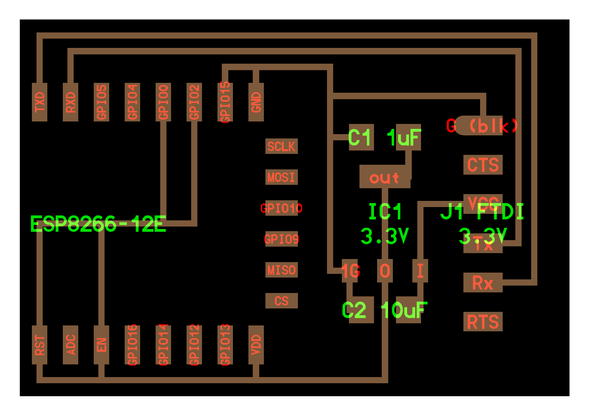
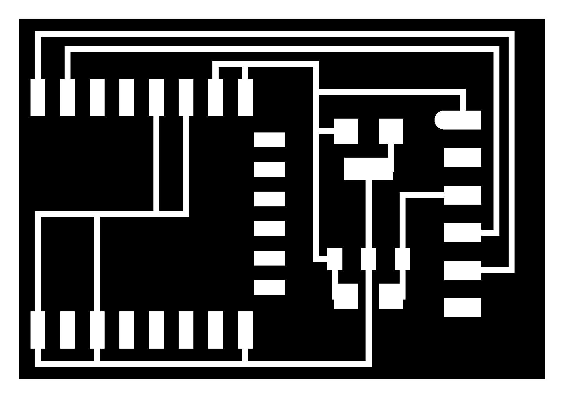
Schematics:

[This is not the best board I made; suggestion: keep reading]
[Make sure to correct the dpi if using this; check consistency with the Hello World dpi.]
NodeMCU, flashing the chip, and more
And so I connected the above board to my FTDI interface and used the video tutorial on the lab website to try to get things running - so I tried connecting with a baud rate of 115200 but alas, I got no connection! Just gibberish on the screen.
The gibberish made me suspect that this was a baud rate issue, so I randomly tried several baud rates. When i hit 9600, Something strange was happening; I was trying to use the AT command just to get some feedback (“OK”) or AT+GMR to get the version, but instead what I got on the serial monitor was this:

stdin:2: ‘=’ expected near ‘AT’.
The clear io messages made it clear for me that this was the right baud rate, but a stderror? On such a simple command? what?!
After some googling around I found the root cause for this 5 hour mess:
My ESP8266 was not using AT like the video tutorial, it was using NodeMCU, an open-source firmware and dev-kit that works with lua. Wait what? Lua?! Could this be my lucky day? I’ve written stuff with lua before; it’s a very simple scripting language that is very intuitive with embedded hardware stuff.
Reflashing
At this point I figured I have two options: reflash the device with an AT-based firmware, or continue with Lua. I chose to continue with Lua, but not too soon did I find out I would have to reflash the device too:
Jumping a little ahead here - the ESP8266 allows you to load an “init.lua” script which loads automatically on power-up everytime the device loads. I made a stupid mistake in one of my attempts and loaded a file that caused an infinite loop and an automatic reset on the device.
After reading a lot online, I learned that my device was officially bricked and cannot be recovered using just the serial interface. I would have to reflash it.
The flashing process is as follows:
-
Download the right bin file. I could’ve switched to AT at this point but decided to stick with nodeMCU. Here’s a link to all the releases
-
Hold GPIO0 at zero
-
Toggle Reset 1->0->1
-
Flash device using esptool.py (
sudo pip install esptooland then as shown below)
The Hello World Schematic, as shown above, ties the Reset and GPIO0 pins to VCC with no possibility to set them on zero. So basically, I was stuck with no ability to flash the device. So, I remilled the board with two buttons with a pull-up resistor that allow toggling those pins:
Yuval Wifi 2.0
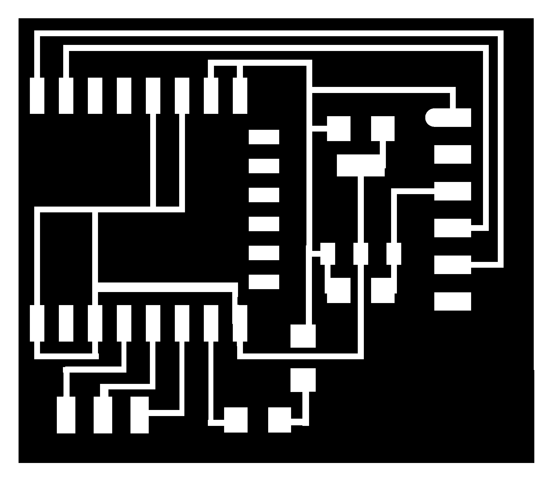
Schematics:

(make sure to correct the dpi if using this; check consistency with the Hello World dpi. Also, it’s a fairly large board on the Y axis so I recommend using a 90 degree rotated copper piece)
As always (baaaah), NodeMCU’s pinout is different from the standard chipset pinout. Some googling and this was solved too - those are the numbers in blue on the schematics file.
Given that we don’t really know what firmware is installed on the WiFi chips, I strongly recommend making the above board instead of the Hello World board, that does not allow for reflashing.
How to reflash
After milling the above board, using the hot air gun to desolder the wifi chip, resoldering and making sure all connectors are working, I took the following steps, after installing esptool.py and downloading the right .bin file:
-
Hold GPIO0 button
-
Toggle RESET button
-
Keep holding GPIO0 button!
-
Erase the current flash:

- Reflash bin:

My Code
Finally, everything was set to start coding. A great IDE to use for NodeMCU is called Esplorer. I particularly enjoyed it because it’s written in Java which makes it cross-platform and I can use it on my mac.
Here’s how Esplorer looks like when it’s first opened:

The right side is the serial interface with the board; When I hit the right baud rate (9600) and reset the device I get the boot notice, which tells me the device is connected properly:

Next, I wrote some lua. Using online tutorials and modifying them for my needs, I created a very simple web server. It has 3 options: an option to turn the LED on or off; an option to set Clockwise or Counterclockwise rotations for the final project, and a “dispense” option. The LED option was implemented, the remaining two gpio pins will be routed and connected to the motor circuit board during final project week.
Here’s the init.lua file as it stands now. (remember to change SSID and password if you’re using this)
Final
Here’s the board that allows reflashing (there’s a small wire surgery here because of a mistake I made by rerouting the button; the above trace files already have that corrected):

And here’s a screenshot of the website:

Lastly, here’s a video of everything working: