
Week Eleven: Output Devices
Operating a motor and an LCD together with daughterboards
Background
This week our assignment was to work with output devices: Motors, LCDs, etc.
Design
My final project is going to be a “next gen” toilet paper dispenser, so this was a great week to make progress on this front.
I focused my efforts on
- Building modular units that will work well with the Fabduino I built during input devices week
- Operating an easy-to-change LCD display
- Activating a step-motor on the push of the button
LCD
My first task was to make the LCD work. This took over a day! Originally I looked at this design from the Arduino tutorial and aimed to replicate it. I made a daughterboard with two 2x5 connectors. Using the potentiometers that we have at the lab proved to be a bad idea; they are easily breakable and seemed like I could not get anything right. I struggled with this for several hours, and here is what I did wrong:
- Broke the potentiometers by using a wrong screw-driver
- Looked at the spec and try to copy it without understanding (bad!)
- Soldered the LCD to pins 1-15 instead of 15-1 (didn’t look at actual pin numbers)
- It also took me a while to understand the LiquidCrystal library. I was again confused with all these pin numbers changing hands all the time.
Also, here’s a tip. No, not a tip. A command. An order: Put an LED on any board you make!
I ended up making a miniature daughterboard, that is pretty much only used to set the right contrast voltage. I shamelessly copied the value of the resistors and the connectivity from Neil’s Hello World LCD example. The Fabduino code was later taken from the above example and adapted to my needs. Here are some links (dpi 1500 - careful):
4 wires connect from the daughter-board to the LCD: VCC, V0 (Contrast) and 2xGND (actual ground and setting R/W to 0).
The other 6 wires are data pins and they are connected directly to the Yuvalduino. If you are using my code, here’s how the wire should look:

Here’s a photo of how it all looks (code to follow in a sec after I explain what I did with the motor):

Motor
Here too, a lot of failures to learn from and about 5 failed milled boards. I decided to use the step motor because the final project will require me to determine precisely the speed and length of the turn. I used as a basis Neil’s bipolar motor and board, but had to make some adjustments. There is a lot of data around the fab sites on the step motor, but here are some important things I had to spend a lot of time looking for.
-
colors (some keywords if you search for this later on - hello from 2016!: colors, step motor colors, step motor wires, step motor coloring, step motor pinout):

-
The step motor requires a 9V power (I used a 9v battery, or as I call it, a ‘we all put our tongue there at least once’ battery). Use thicker traces because they will draw A LOT of current.
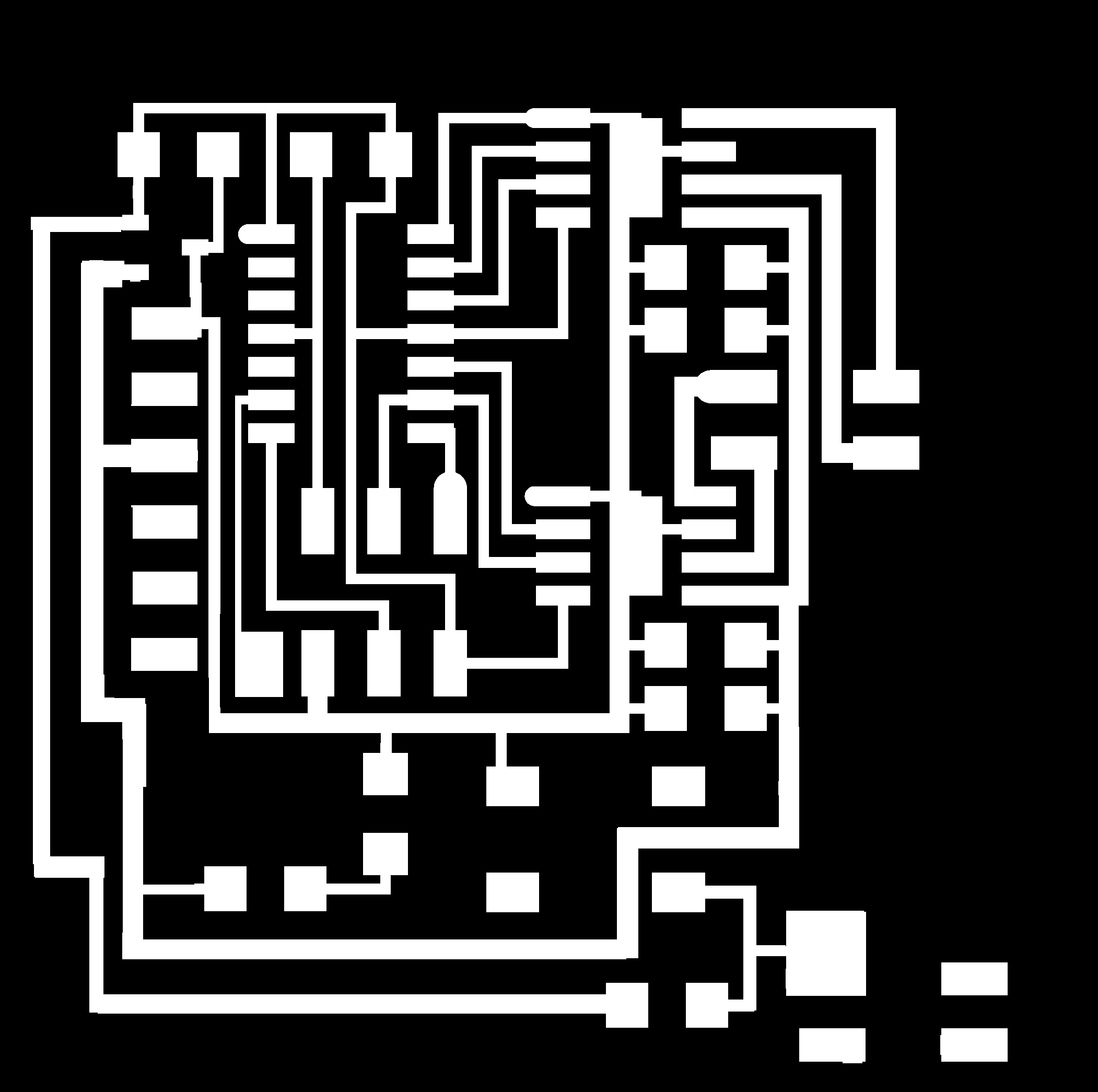
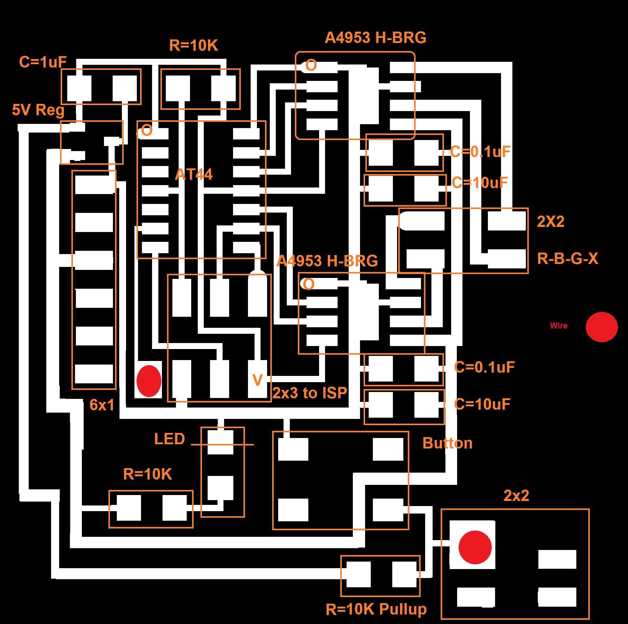
Here are the files for this daughter board (dpi should be 1269.289 - careful):
Some cheats regarding these files:
-
See the red dot? Solder some insulated wire (tips exposed) between the spots. I originally couldn’t find any easy way to transfer data from the new button to the old YuvalDuino so made this bypass. It works.
-
I changed the 9v/gnd input to look like an FTDI input, and then used crimps for the battery to fit.
-
Here’s how you should connect the motor (use this for Neil’s board too):

-
Another key thing on the Hardware side: We have two voltage sources: The Yuvalduino takes 5v from the computer and the motor daughter board takes 9v from the battery. The information regarding the push button is transferred from one board to another. To do this YOU NEED COMMON GROUND. Find a GND pin on both boards and connect it via wire. Otherwise weird stuff happens. Trust me on this.

After several failed attempts to work only with my fabduino devices I decided to use an attiny 44 to control the step motor, but to transfer data between it and the YuvalDuino. Given that Neil’s code is in C, I used C.
I added button support and added an interrupt mechanism for the button: the motor doesn’t run on an infinite loop anymore, but only when the button is pushed.
And here’s a video that shows the motor working as a standalone device:
Finally, for the YuvalDuino code. On the push of the button (push data is transferred via the bottom-right connector on the daughterboard), in addition to the motor rotating a tad, we also update the number of rotations on the LED. This is great because eventually this will tell us when we need to replace the TP in the house. The reset button resets the count.
For this, in addition to creating common ground, I also needed to write a short debouncer for the button to stay stable and not increment the count when I’m not pushing.
Here’s the Arduino Code with debouncer, button, and LCD support
Here’s a photo of everything together:

And here’s a video of everything together!
Yay.