Week Three: PCBs!
Wow, what a weekend - I made a fully working USB device, literally from scratch.
Background
This week we were given a final design for an ATT tiny based Programmer. We were to mill the PCB, solder the components, program the board and then fuse it to make it a programmer on its own. Links to all of this are here.
Vinyl Cutter Attempt
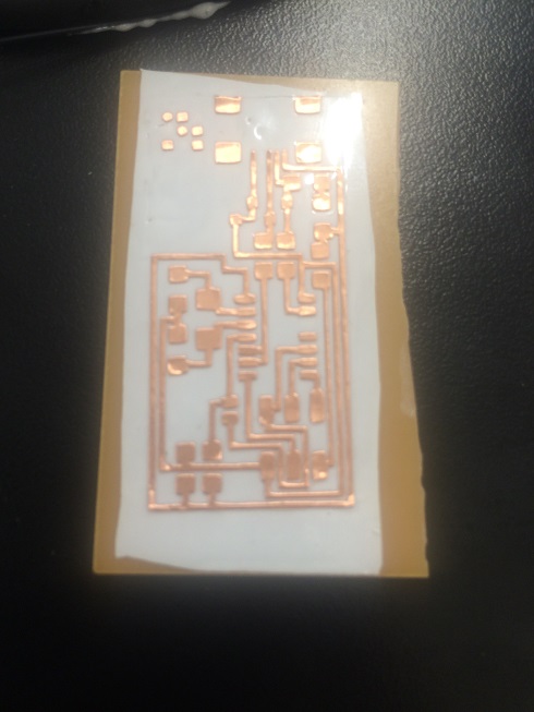
There was a lot of pressure on the Modela milling machine the first few hours, so I started off by using the Vinyl cutter - cutting the traces on an adhesive conductive material. It was extremely easy to print it, but once I started soldering (more on that later), the heat actually affected the adhesive as well, moving the traces around and making it extremely hard to solder. I stopped half way through, but here’s what I had when I stopped:
Modela
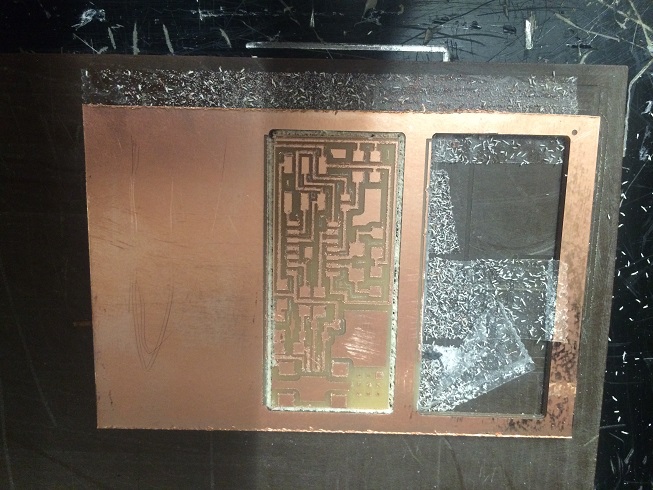
The first step in making a PCB is the Modela milling machine. We used the trace file (link above) to etch the traces of copper (or, to be more exact, everything but the traces of copper). The Tiny TTY board that we’re making connects a USB device to the main chip. Here are some photos:
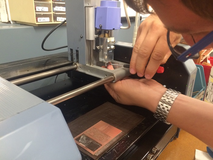
- The “Head”: We used 1/64” to cut the traces, and 32” to cut the perimeter out of the metal piece. Here’s me changing the head between etching and cutting:
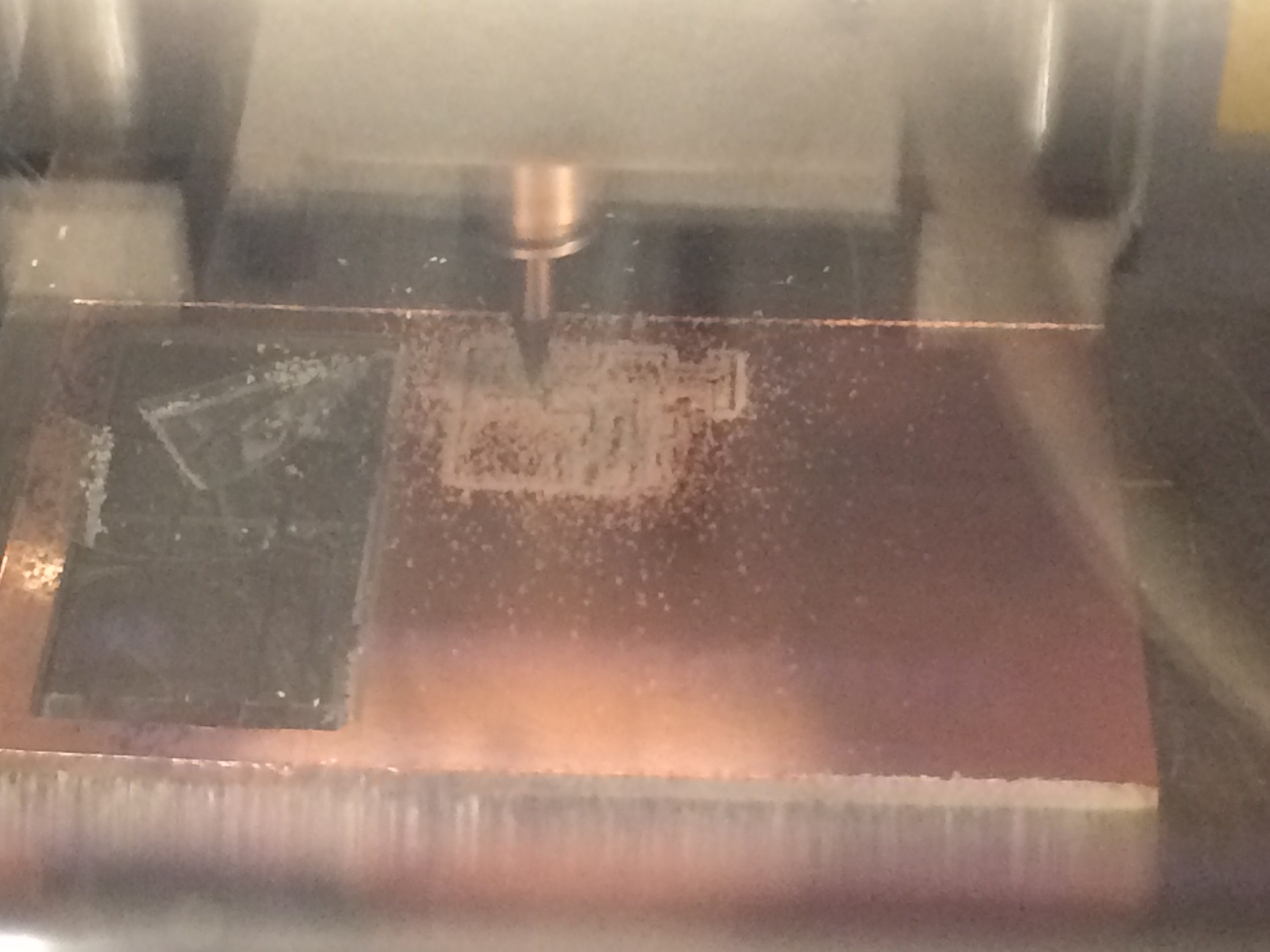
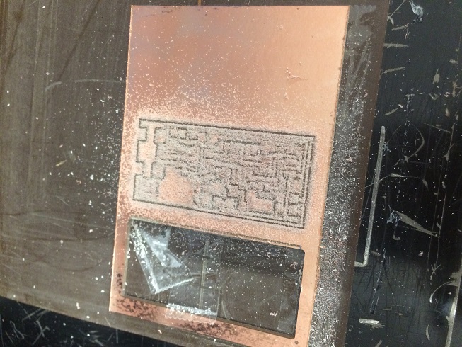
- Here’s some photos of the Modela at work, and the outputs of each run:
- And here’s a video of the Modela cutting my board:
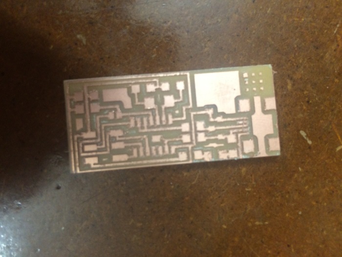
- And the final product - bare PCB:
Soldering
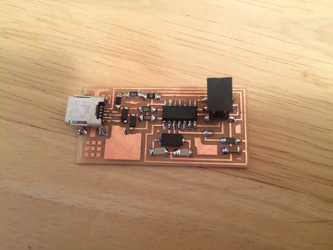
After printing the bare PCBs, I had to solder the actual parts: add resistors, diodes, capacitors, UBS connector to the PCB. The last time I soldered was when my dad taught me how to do it when I was 10 - we were making a Joystick switch to change between the “wheel” and the normal joystick we had back home. Those lessons proved themselves invaluable!
Here’s the final soldered piece:
Programming
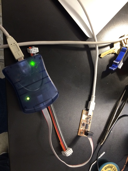
The PCB can be used as a master or slave programmer; at first, we use it as a slave; the USB input is only there for power, and the 6-pin header connects to an already-made programmer (in my case I used a commercial one), to be programmed. More on that in the links above. Here’s a photo:
Once programming is done, we remove the 0 ohm bridge and the solder blob to make the board immune from further programming attempts.
Cover
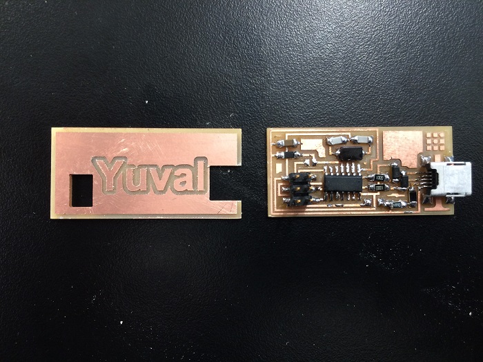
To be safe when moving the board around, I printed a top cover for it that says my name, and has specific holes cut out for the USB cand 6-pin connectors. The PNG files can be found here (traces) and here (outline).
I printed (two steps, just like the PCB itself) the board. Here it us together with its functioning counterpart:
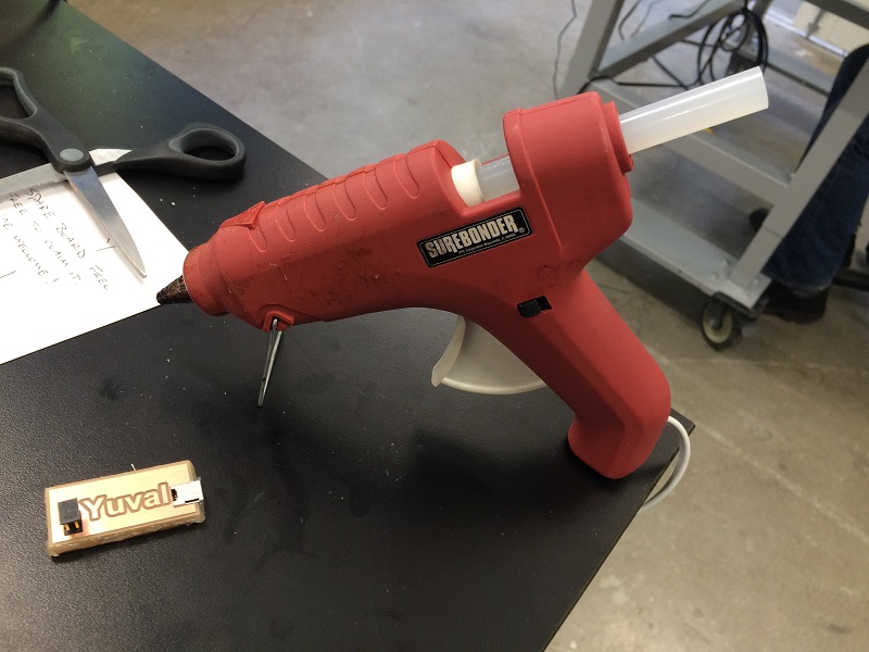
Final step - use a glue gun to get it all together:
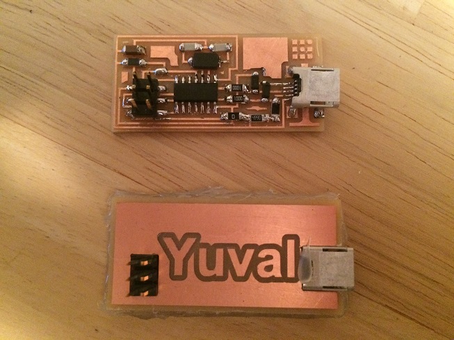
I then made another board to make sure my board works properly (it’s amazing how much faster things are done the second time around! this one took about 30 minutes from start to finish). Here they are together:
Things that went wrong, and how to avoid them
-
Not milling enough material, or inconsistency across board: Must make sure the board lays flat on the piece inside the Modela. Because we are only itching 0.1 millimeters, it’s important to use 2-sided tape evenly across the entire piece.
-
Short-circuit: it is highly recommended to use a multimeter to check for any short circuits. This saved me more than once!
-
When applying hot glue for the first time, I wasn’t careful and some traces of copper were “torn off”. I had to fix this with extra wires (good thing the final packaging makes it all hidden…).
-
Don’t forget that some command require sudo.

