
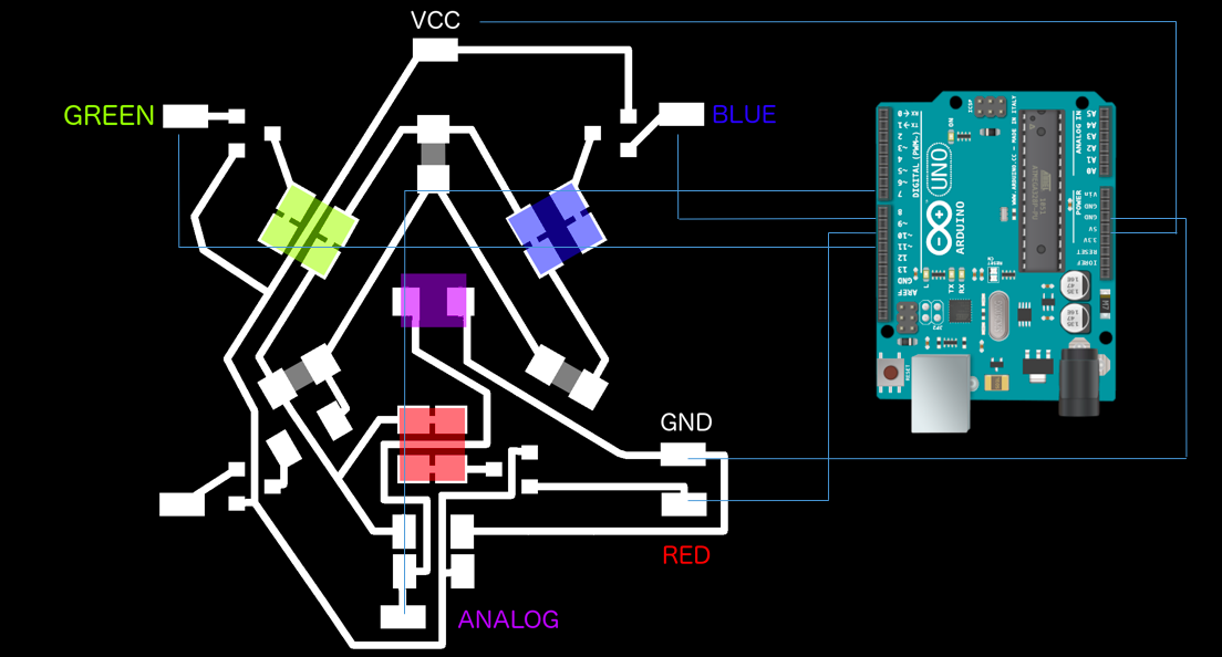
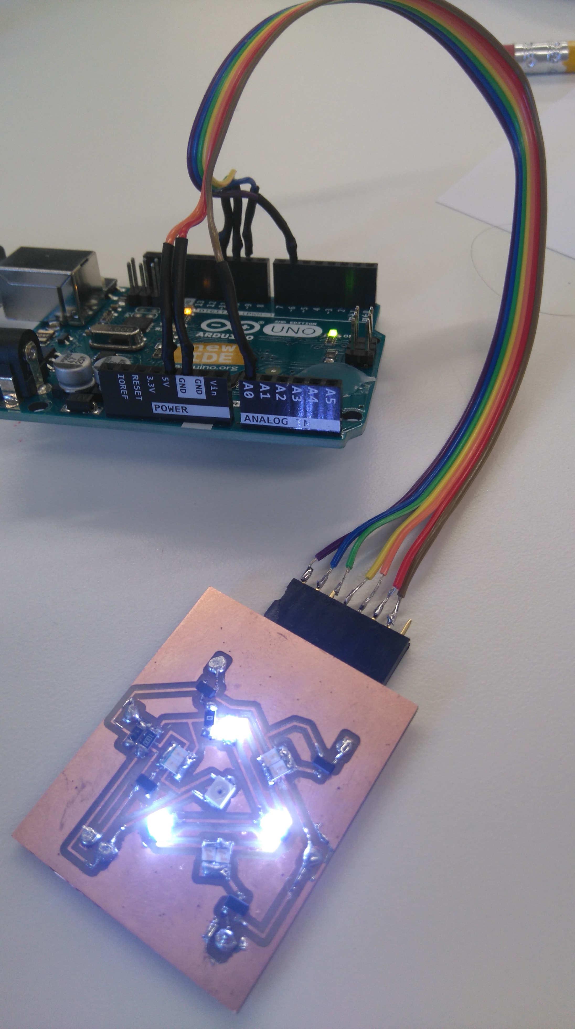
My setup and pinout is shown below:
Color Sensor --> Arduino
RED --> Pin 9
GREEN --> Pin 10
BLUE --> Pin 11
WHITE --> Pin 6
ANALOG --> Pin A0
VCC --> VCC
GND --> GND
Connect the Arduino Uno to the USB port. Open the Arduino software select the port connected to the arduino (Tools -> Port). Load the following code into a sketch and upload the sketch.
int LED[4] = {9,10,11,6},i, j ;   // DECLARE  R   G   B  PINS


            void setup()

            {

            Serial.begin(9600);

            for(i=0;i<4;i++)                 // set LED pins to OUTPUT

            pinMode(LED[i], OUTPUT);

            }


            void loop()

            {

              for(j = 0 ; j < 4 ; j++)                    //  CYCLE  PINS and set pins low.

              {

                analogWrite(LED[j],0);

              }

              for(j = 0 ; j < 3 ; j++)                    //  CYCLE  PINS

              {

                for(i =0 ; i < 255 ; i++)                  //   CYCLE PWM VALUES - this changes the brightness of the LED from 0 - off to 255 - completely on.

                {


                 analogWrite(LED[j],i);

                 Serial.println(1024-analogRead(0));            //  PRINT  VALUES - to view these open the serial monitor.

                 delay(10);

                }

            analogWrite(LED[j],0);


            }

            }
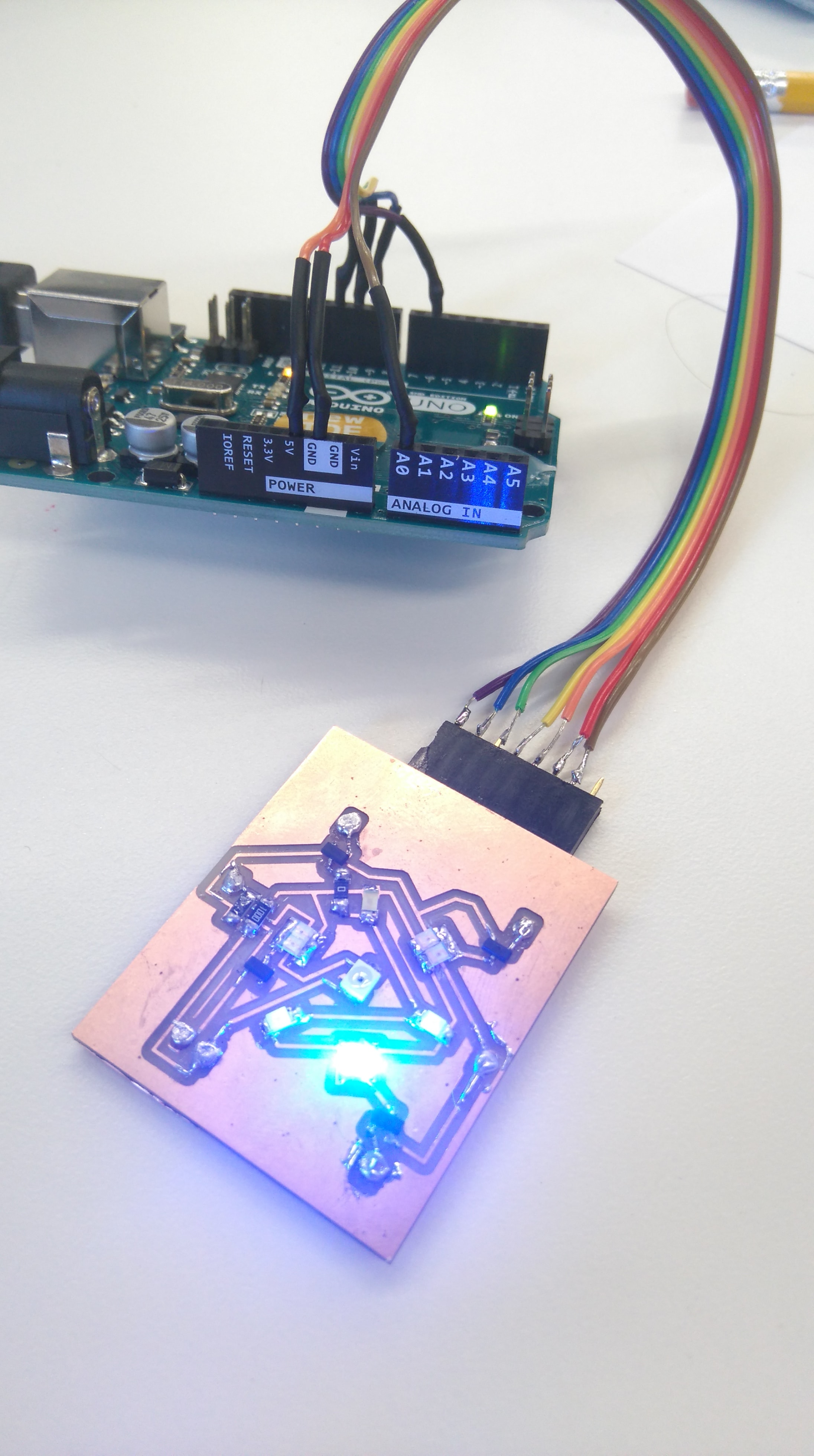
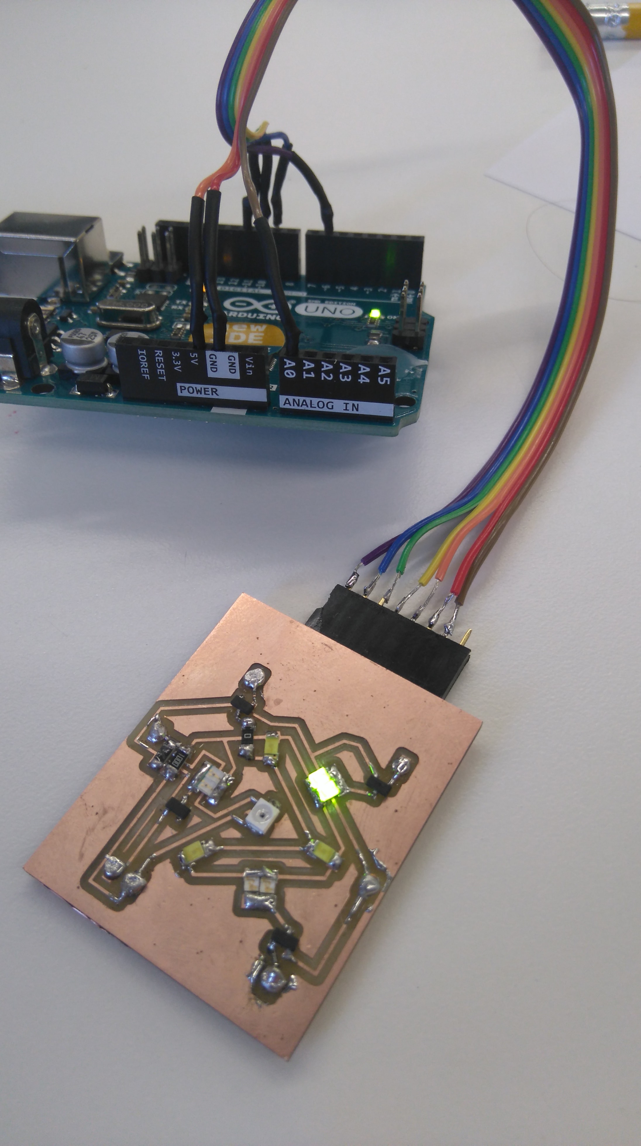
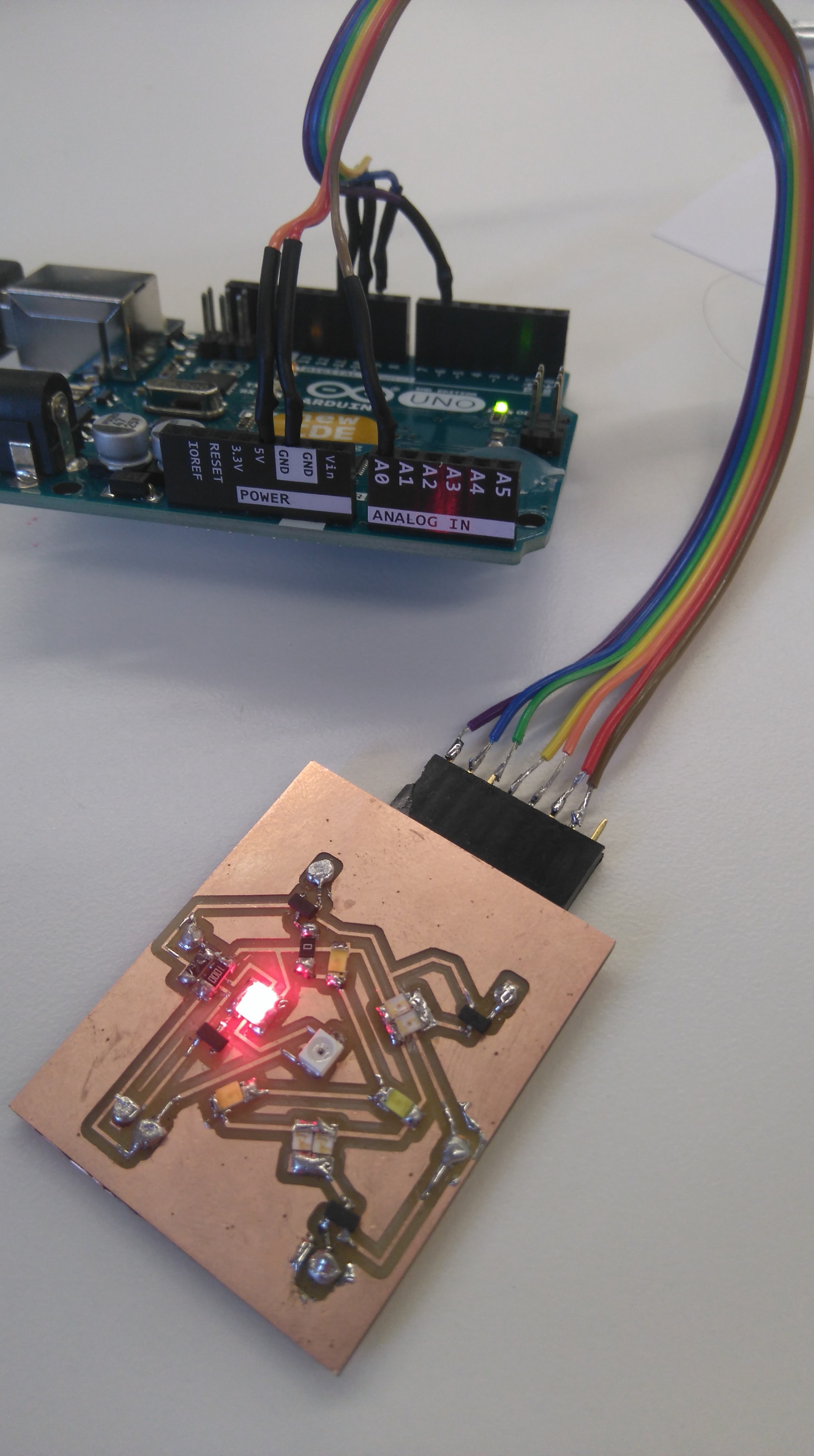
You should see the lights alternating and each color increasing in brightness.
I decided to use processing to read from the analog 0 pin of the arduino. I downlowded processing and began to get to work trying to understand how it works. I ran into a couple of problems that took quite a while to figure out:
1) Firstly my Phototransistor was soldered on backwards and I was therefor not getting any readings that made sense.
2) You can only draw lines in the draw function.
Here is my processing code
import processing.serial.*;
Serial myPort;
float xPos = 20,prevtime=0;
float inByte;
String inString;
int i = 0;
float inBytetotal = 0;
float inByteave = 0;
int ave = 0;
void setup ()
{
size(700, 700); //Set canvas size.
// List all the available serial ports
printArray(Serial.list());
myPort = new Serial(this, Serial.list()[2], 9600);
myPort.bufferUntil('\n');
background(255); //Set background colour of canvas
}
void draw () {
// draw the line:
stroke(255, 0, 0);
line(xPos, height, xPos, height - inByteave);
inBytetotal = 0;
inByteave = 0;
if (xPos >= width) {
xPos = 0;
background(255);
} else {
xPos++;
}
}
void serialEvent (Serial myPort)
{
inString = myPort.readStringUntil('\n');
if (inString != null)
{
inString = trim(inString);
inByte = float(inString);
inByte = map(inByte, 0.0, 1024.0, 0.0, 700.0);
//print(inByte);
//print('\n');
//print(xPos);
//print('\n');
if(i
inBytetotal=inBytetotal+inByte;
i++;
}
if(i==ave)
{
inBytetotal = inBytetotal+inByte;
inByteave=(inBytetotal/(1+1));
i=0;
}
}
}
The video below highlights a couple of things:
1) The Green light is extremely dim and will need to be replaced by a more effective Green LED.
2) The oscillations that can be seen I believe are a result of the PWM frequency and the frequency that readings are measured at - I might have to put a capacitor across the Phototransistor pins...
3) I will need to calibrate light sensor.