It reads the color it is sitting on and displays the hex number on a six digit display.
Several companies have made color sensor module chips. I wanted to make a sensor with display all in one package, I could not find anything similar available.
I designed all the PCB's I made (the color sensor PCB was based on an instructable version - but I did make several adjustments) I also designed the packaging.
All my materials except for the wood were from the fab inventory. The breakdown of components is given in the description of the process below. The wood was 12" x 18" x 2" from Dickson Bros and it cost $15.
Everything was made, this includes:
The color sensor board
The digit display board
The processor board
The wooden box
The 3D printed digit display
3D printing
Vinyl cutting
Electronics design
Computer controlled cutting
Computer controlled machining
Embedded programing
Input devices
Output devices
This process challenged me to integrate the various weeks of skills, it allowed me to experience how to do things the hard way in most cases :) I was wandering how accurate I could get my sensor by only utilizing linear mapping functions - I realised it can get quite close which was a pleasant surprise.
This is answered at the bottom of the page.
As an artist this product fascinates me - it provides a way of converting visible color into a digital representation. This would be useful when trying to replicate color, for example when trying to find which color paint was used all those years ago.
I spent quite a while thinking about how I would make the color sensor. After a couple of hours of internet research, I put together a schematic design for the color sensor. The original design was inspired by a design "Your Own COlour Sensor Using LEDs" on Instructables. The schematic they had uploaded for the smd did not make much sense to me - so I created a completely new one.
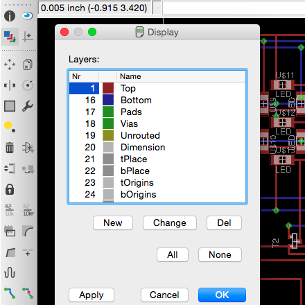
I used Eagle to create the PCB design below:
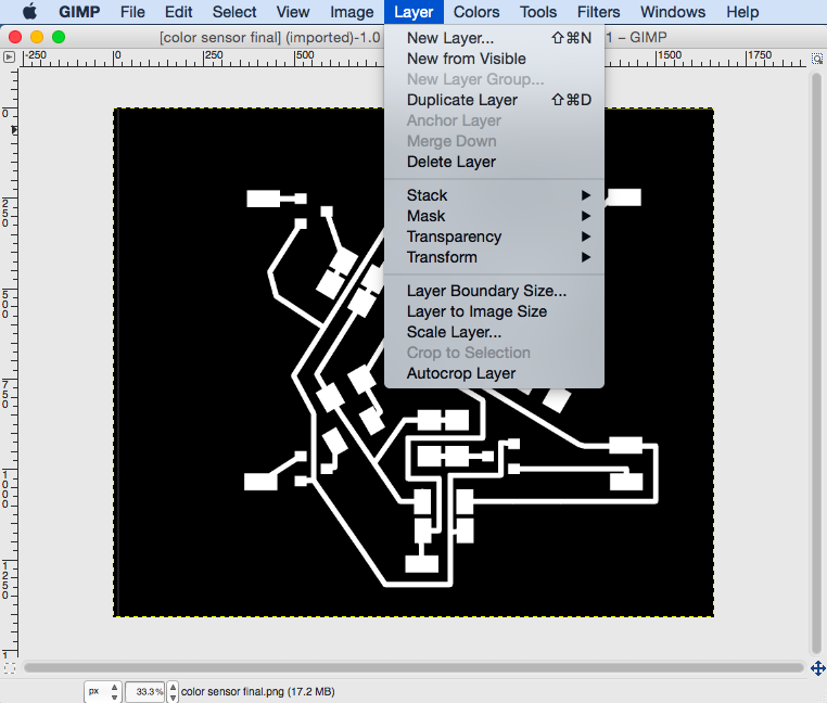
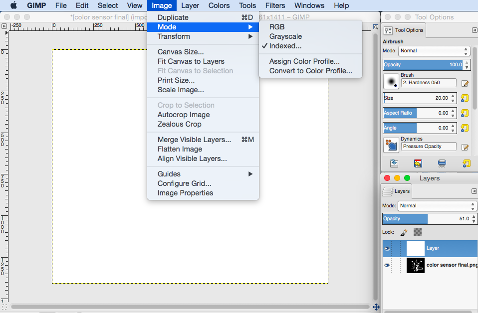
The board is designed to be double sided, but I was not too sure how to do it in eagle – will need to figure that out [I have since figured this out - I used two Eagle layers in the design for the digit display below] – and so I used GIMP to manually draw out the bottom layer. As the bottom layer was not very complicated it did not take too much time to 'route it by hand in Gimp'.
Tips on using GIMP to create PCB designs (although it would probably be best to just do it in Eagle):
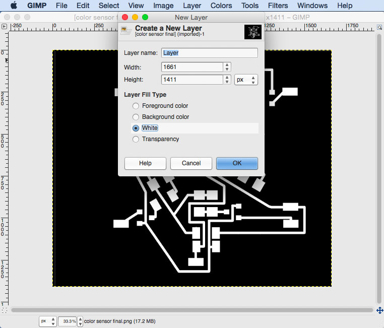
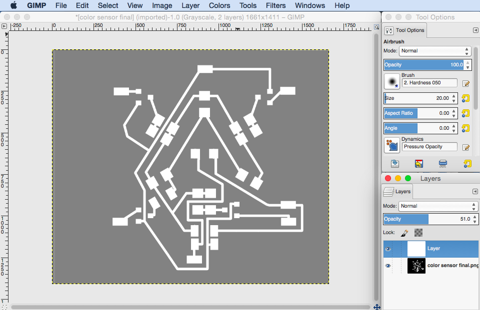
1) If your design is paired with a layer that was created in Eagle then load the monochrome image of the Eagle PCB tracks into GIMP and create a white layer above it.
2) In order to make sure that the pads align for the vias through the board you will need to decrease the layer transparency to about 50%.
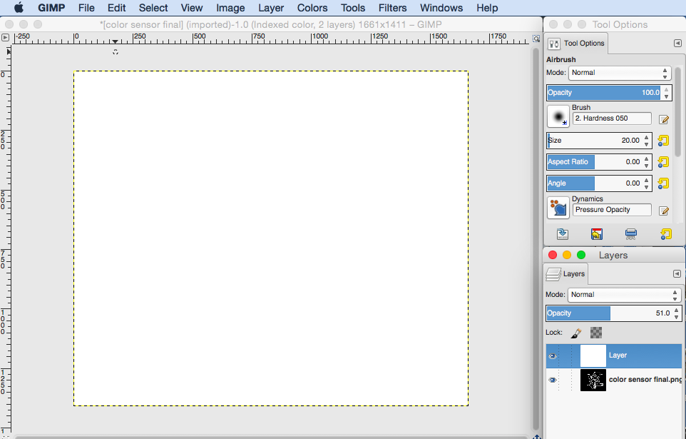
3) You will notice that there is no change in the transparency until you reach 50% at which point the layer goes completely transparent. The reason for this is that the Image mode settings are set to Indexed instead of Greyscale or RGB. Change these settings by going to Image -> Mode -> Greyscale
4) Now you will need to make you white layer completely black as your traces are going to be white by convention. So use the paint bucket tool to paint it black.
5) In order to draw the pads you can use the rectangle select tool and trace over the corresponding pads on the bottom GIMP layer – the size of the pads do not have to be exact as long as they are the same or larger than those below.
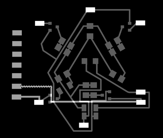
6) In order to draw the traces you will need to be a bit more careful: I found it helpful to change the units in GIMP from pixels to millimeters as I knew that the traces in Eagle were about 0.5mm wide. This units can be change at the bottom left hand corner of the window. Now when you use the rectangle tool to create selections to be filled in white you can make sure the width of the traces are 0.5mm – this is also indicated at the bottom of the window when using the rectangle select tool.
7) NOTE: When you have finished the traces you will need to horizontally flip the layer you created before exporting to png.
8) Make sure that you increase opacity back to 100% before exporting to png.
NOTE: Have fun drawing tracks! (As mentioned above I used the rectagle select tool to make selections and then used the paint tool to paint the tracks, but have since figured out how to draw lines in gimp!!! All you do is make a mark with the paint or drawing tool then press shift and move your cursor to another point)
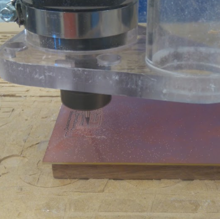
I began by milling on the Roland Mill, but after much frustration and confusion I gave up. Shown below is the traces that were calculated by the mill as well as two failed boards. The mill went sort of crazy at 27% and would draw lines through the board.
ShopBot time!
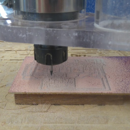
I loaded a new board into the shopbot and began the process again. This time it worked out.
Tips for milling a double sided board:
1) Mill the top layer traces then mill the vias and outline. After this only remove your board from the stage, flip it over (make sure that you alignment is correct) and place it back into the hole. This allows you to align it so that you do not have to re- zero x and y.

TIP - do not do what I did with the via holes. The holes were much too big - make them smaller!
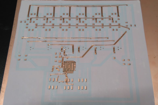
The board came out very well except for a couple of places where the tracks were too close and it did not cut between them. I manually cut these traces with a craft knife and loads of patience.
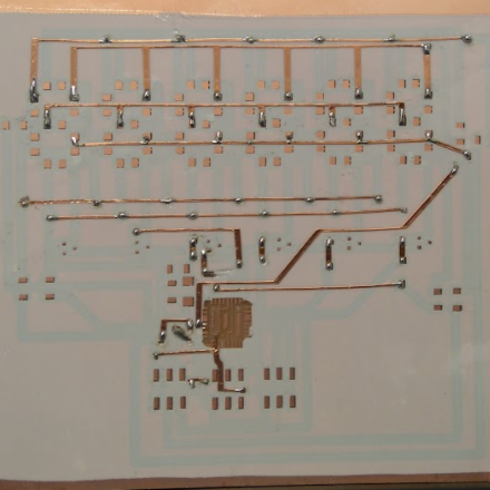
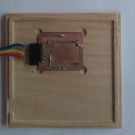
Soldering Time!!!
I began by Soldering the top side of the board – as well as placing in the vias. Oh my goodness! Make sure that you have the correct size holes for the vias – mine are way too big and the vias do not fit very well. It took me soo long to fill the board that I ran out of time. I will need to program it asap.
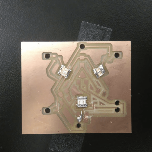
As you may have noticed I soldered an IR phototransistor in instead of the one for visible light. (It took me quite a while to realise this, but I eventually replaced it.)
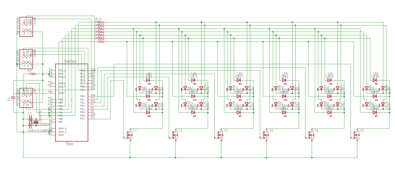
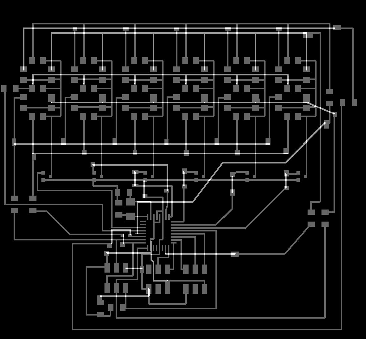
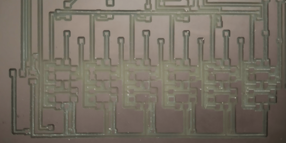
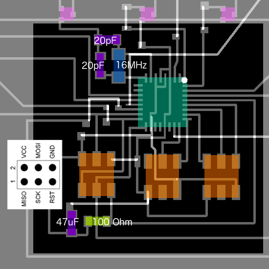
I wanted to make a six seven-segment-LED display that could pair up with my color sensor and display the corresponding hex values. The reason for creating a display instead of using the one provided was that I wanted to use different colored LEDs. I began by doing some research online to see how seven segment led displays work and then began to put together the PCB in Eagle.
Below is an image of the schematic. (You may notice that I connected the 16MHz resonator to pins 9 and 10 of atmega328 instead of pins 7 and 8. In a later version fo this board I fixed this problem)
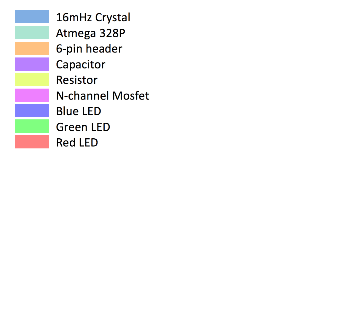
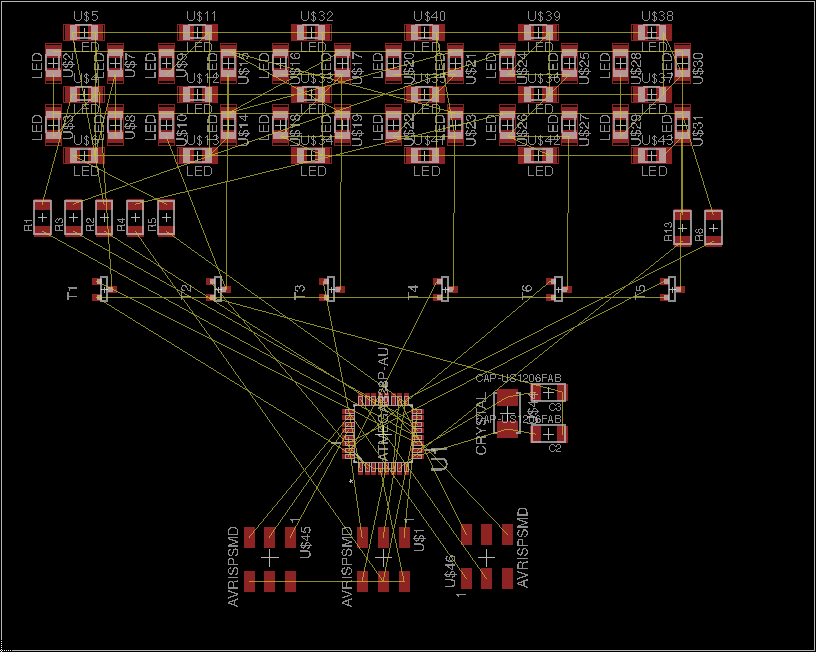
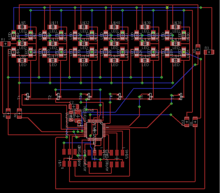
Below is a illustrated image of the PCB with a key for the components used.
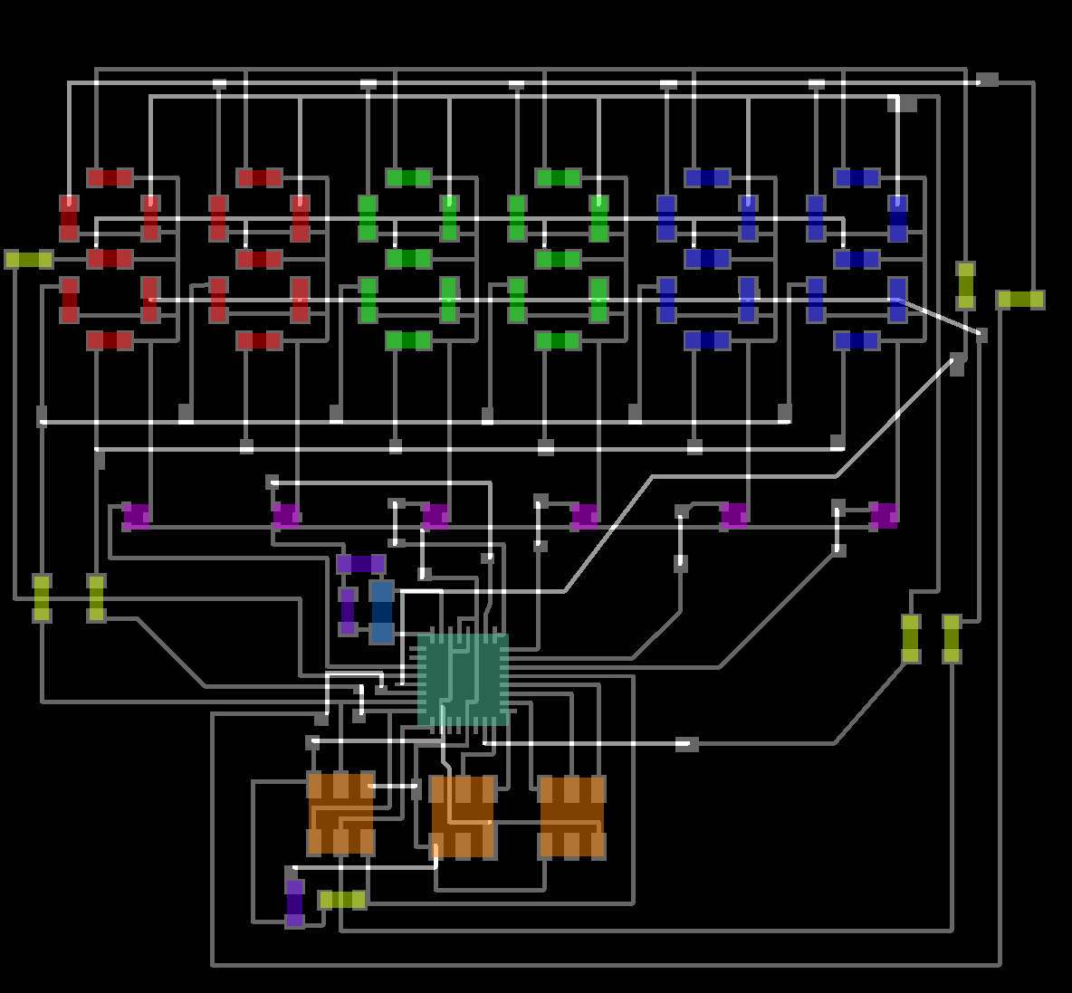
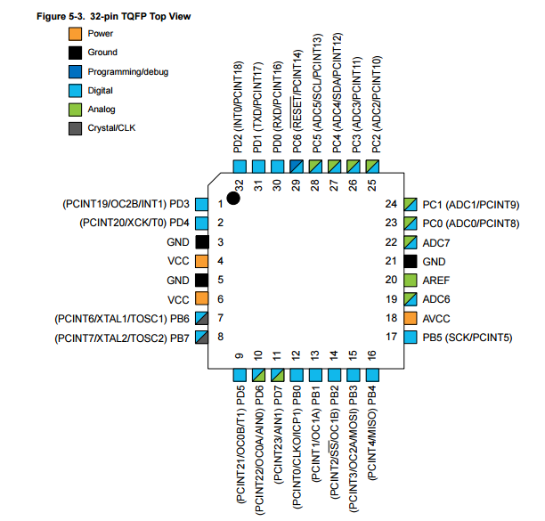
I used the atmega138p microcontroller - the pinout is shown below.
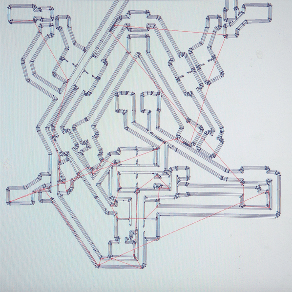
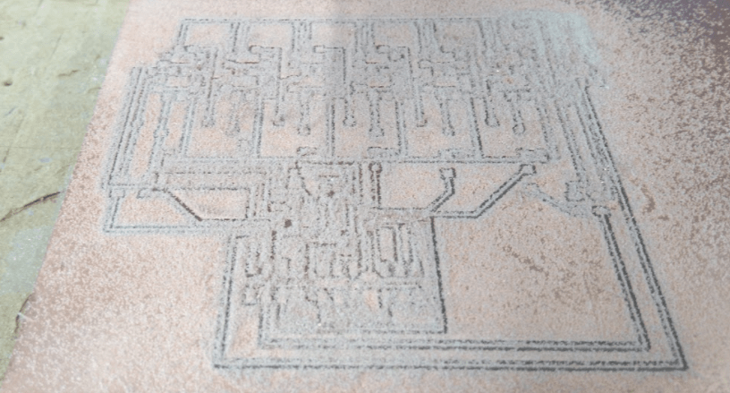
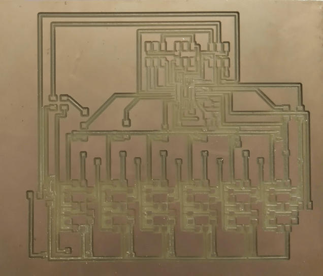
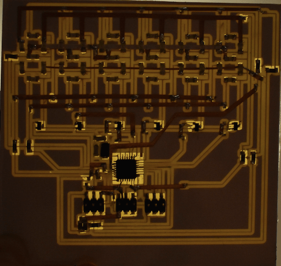
Okay - now for the routing!. I ended up using two layers with vias between them. Instead of milling on both sides of the board I am going to try utilize the epoxy vinyl and copper vinyl...
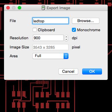
Okay - ALL DONE. Now I use the layers tool to control which layers appear inorder to save the traces on the top separate from those on the bottom as monochrome images. The save options I change to 900dpi so that the resolution is really good.
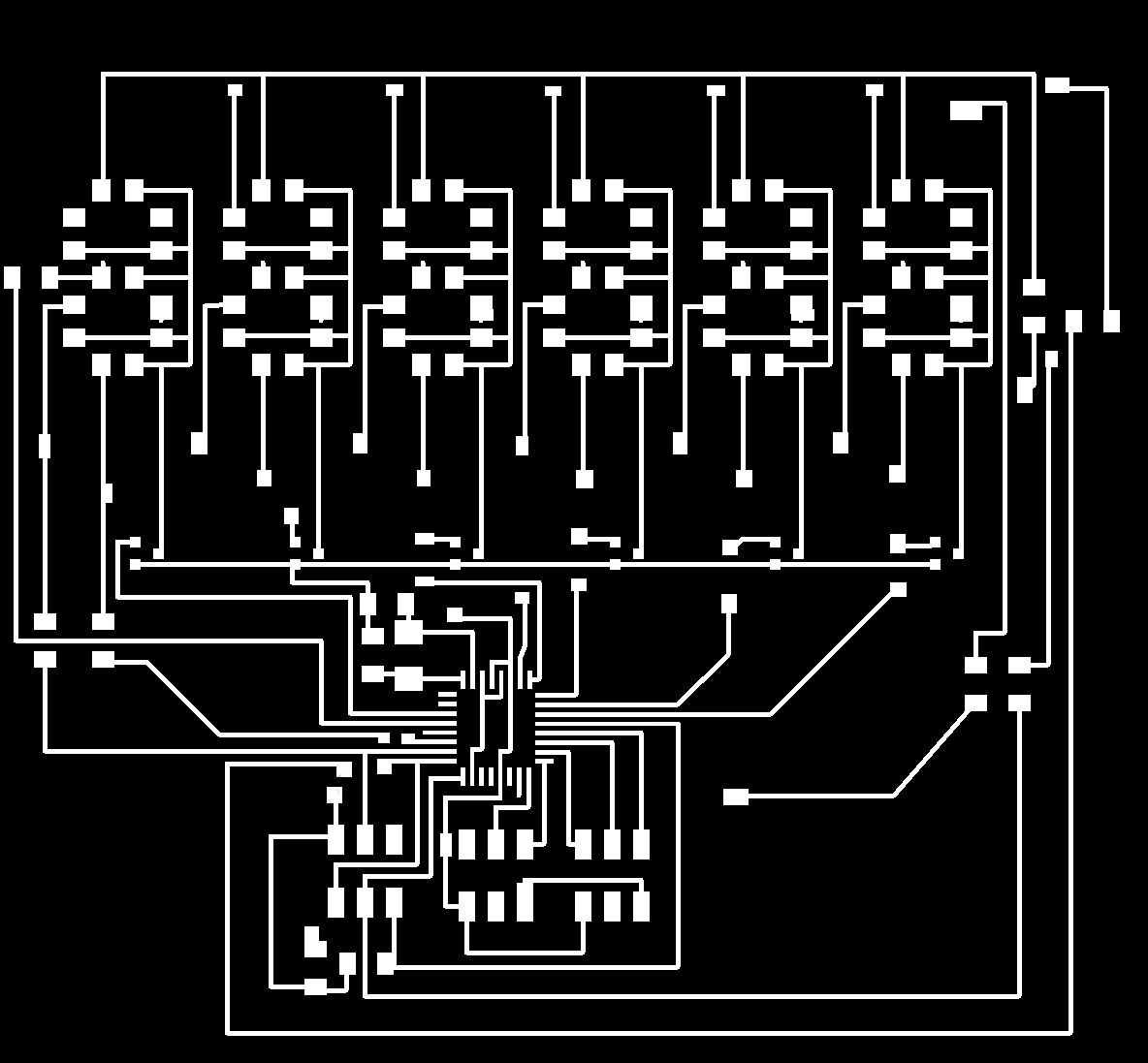
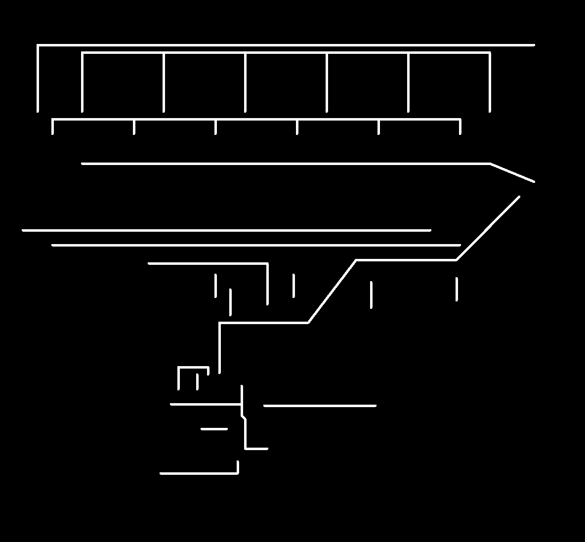
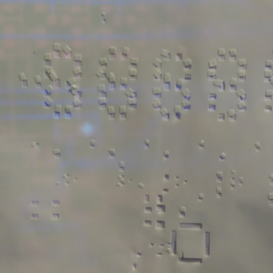
Here are the raw monochrome images.
I uploaded the monochrome images into gimp and saved them to different layers. I then changed the layer opacity to allow me to work with both layers in view. The reason for editing is to create pads on the bottom layer so that the vinyl cut copper layer will be able to connect to it as well as to create a layer for the insulation epoxy vinyl (this will separate the copper vinyl layer from the bottom milled layer)
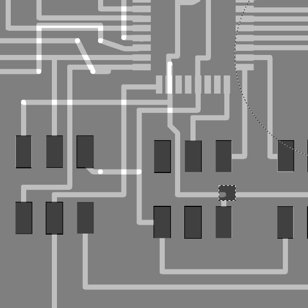
I reset the opacity to 100% on the layers and then exported the image to png three times each time showing different layers but hiding the ones I did not want.
BOTTOM LAYER - milled layer.
COPPER VINYL LAYER.
COPPER VINYL LAYER inverse

EPOXY VINYL LAYER.
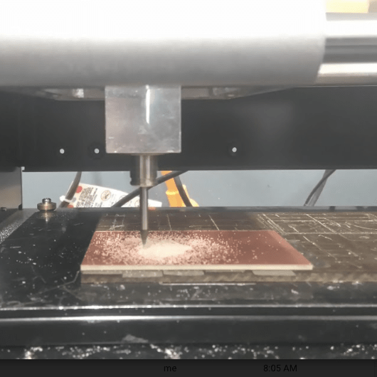
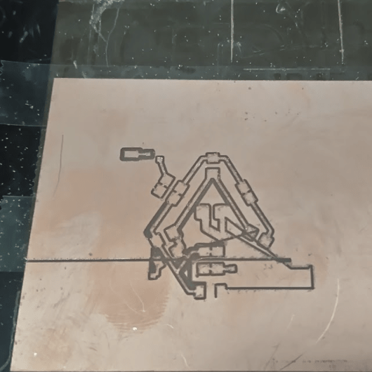
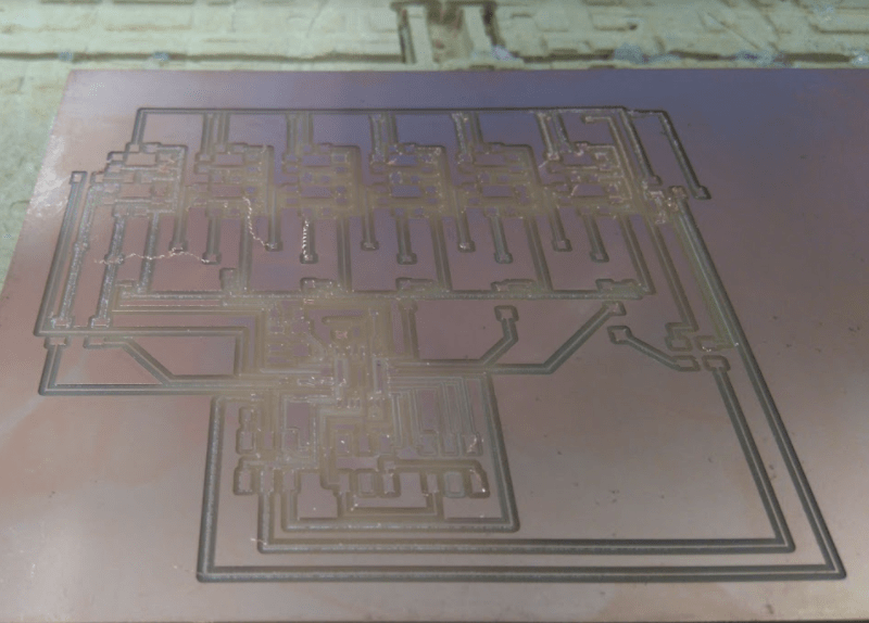
Firsty I milled the bottom layer - make sure that the tool diameter of the 1/64" mill will fit between traces and pads.
I used the shopbot to mill the board - there were no problems.
The vinyl cutting was not as streamlined. The copper traces were much too thin and therefore when the blade was cutting the copper it pulled up the traces as well. I managed to solve this by:
1) Doubling the width of the traces manually in GIMP.
2) Decreasing the force of the blade to 45g.
The epoxy on the other hand worked very well with the default settings.
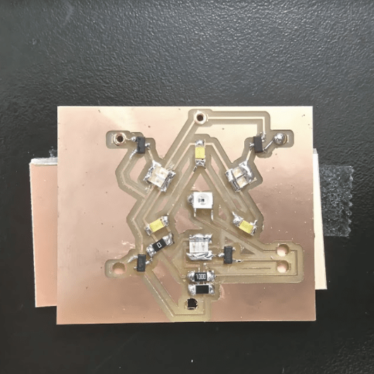
Assembling the layers took a lot of patience and time - but it all came together eventually.
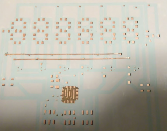
Soldering also took a lot of patience and time - TIP use the Voltmeter/Ammeter/Ohmmeter frequently to make sure that there are no short circuits.
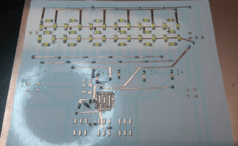
ALL DONE!.
I COULD NOT SOLDER THE TRACES TO PIN 11 AND 12 OF ATMEGA328, BUT MANAGED TO SOLDER INSTEAD TO PINS 10 AND 11 RESPECTIVELY.
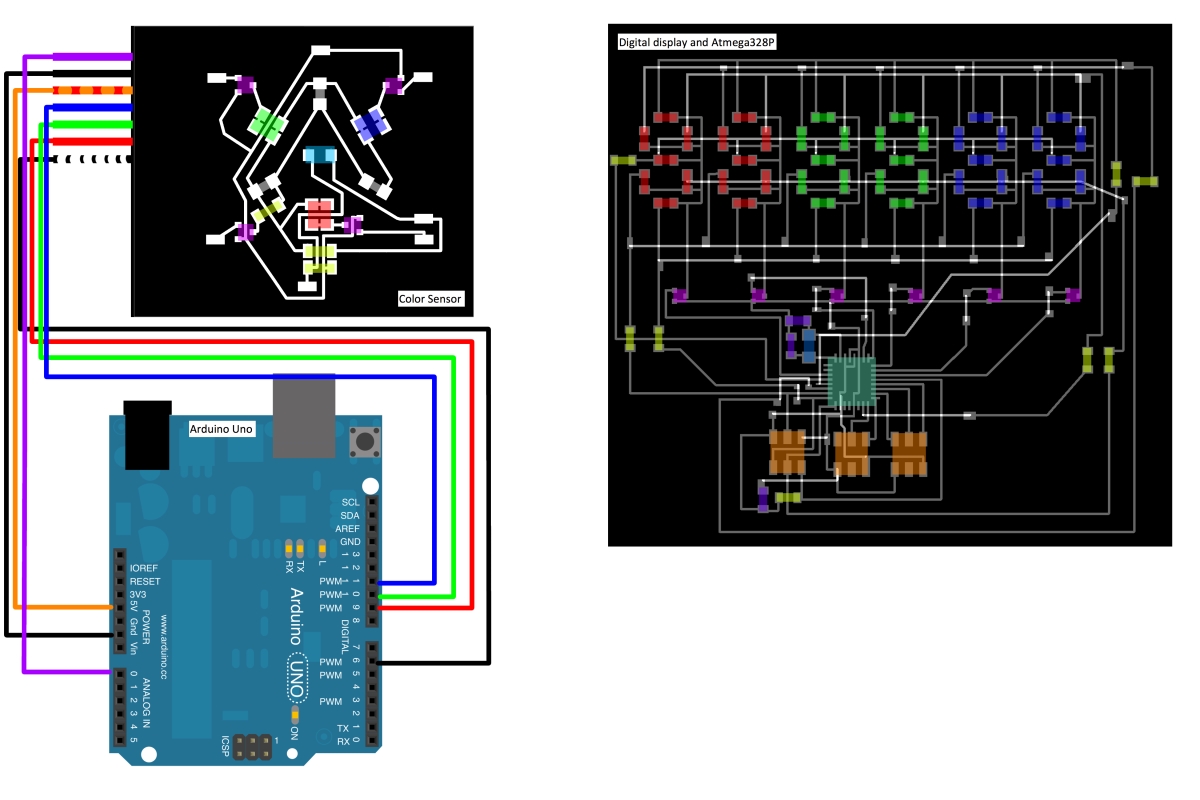
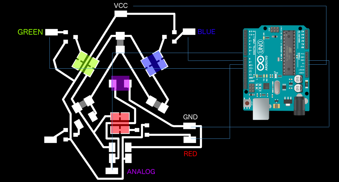
My setup and pinout is shown below:
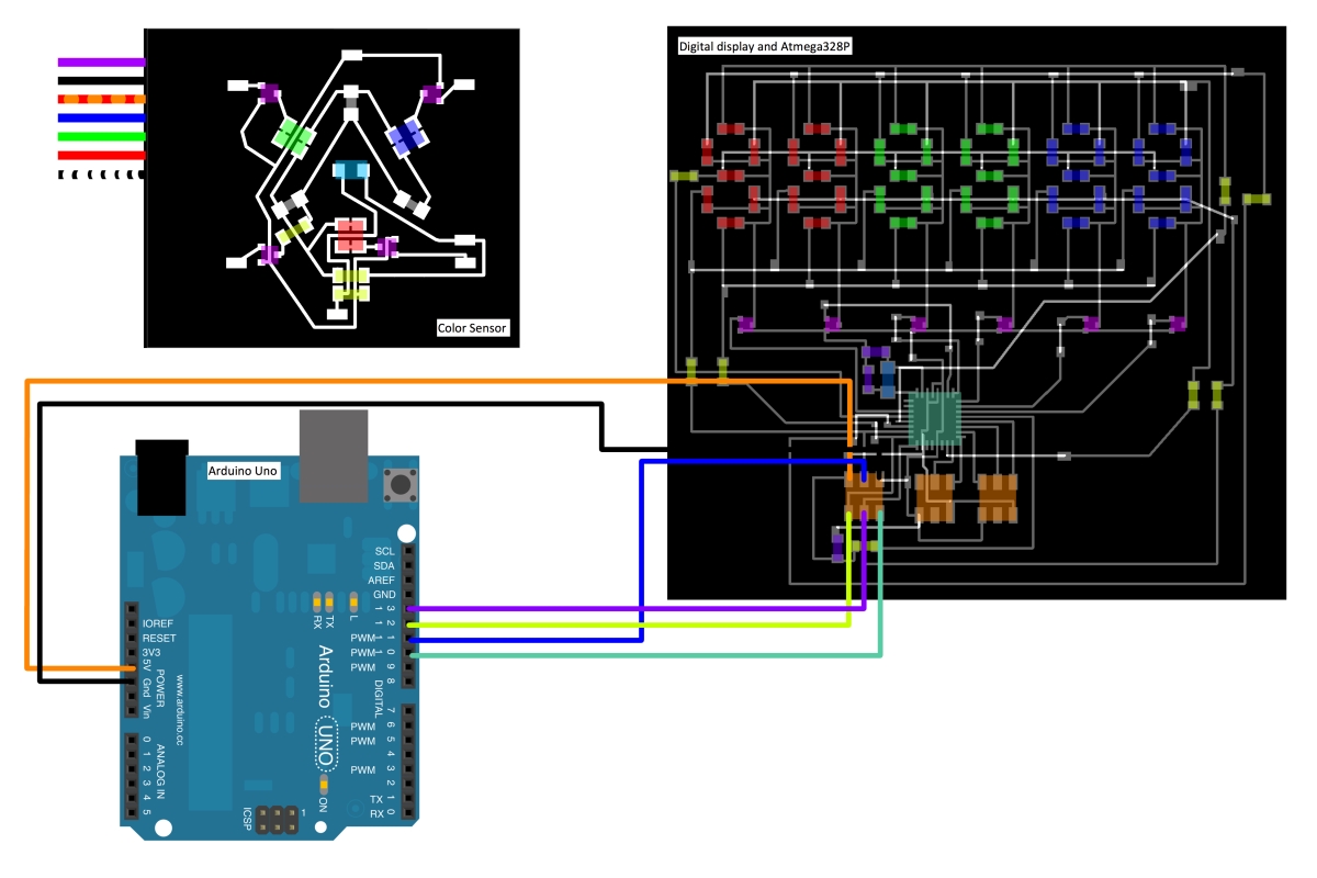
Color Sensor --> Arduino
RED --> Pin 9
GREEN --> Pin 10
BLUE --> Pin 11
WHITE --> Pin 6
ANALOG --> Pin A0
VCC --> VCC
GND --> GND
Connect the Arduino Uno to the USB port. Open the Arduino software select the port connected to the arduino (Tools -> Port). Load the following code into a new sketch and save it as 'teston'.
int COLORSENSOR[4] = {9,10,11,6},i, j ;   // DECLARE  R   G   B   W PINS
float readValue[100];                     // initiate float array with 100 elements to store the values read in from the analog pin.
float averagereadmap[4];                  // initiate float array to store the average value (mapped) read from the analog pin. Four elements to store the average for R,G,B,W
float averageread[4]={0,0,0,0};           // initiate float array to store running total of read values.
long int inthex[4];                       // initiate an int array to convert float stored in avaeragereadmap array to int.
String hex[4];                            // initiate a string array to store hex values for each led input.
void setup()                              // all code in setup will only run through once.
{

  Serial.begin(9600);                     // Sets the data rate in bits per second (baud) for serial data transmission.
  for(i=0;i<4;i++){                       // set LED pins of color sensor to OUTPUT
  pinMode(COLORSENSOR[i], OUTPUT);}
  for(j = 0 ; j < 4 ; j++)                //  CYCLE  PINS
    {
      digitalWrite(COLORSENSOR[j],HIGH);   // Switch LED corresponding to j pin value on
      delay(100);                          // Delay before reading to allow led to get to full brightness.
      for(i=0 ; i<100 ; i++)               // Read analog input 100 times.
      {
        /*if(j==0) {readValue[i] = analogRead(A0)-99;}
        if(j==1) {readValue[i] = analogRead(A0)-122;}
        if(j==2) {readValue[i] = analogRead(A0)-77;}
        if(j==3) {readValue[i] = analogRead(A0)-168;}*/
        readValue[i] = analogRead(A0);
        Serial.print(readValue[i]);                      //to view these values open serial monitor
        Serial.print('\n');
        delay(10);
        averageread[j] = averageread[j]+readValue[i];     //add value to a running total of read values form analog input
      }
      digitalWrite(COLORSENSOR[j],LOW);                   // Switch LED corresponding to j pin value off
      averageread[j] =averageread[j]/100;                 // take average of read values
      if     (j==0) { scaleAndProduceHexString(0, 911);} //Red : The value on the left should correspond to the maximum value read in serial monitor when RED led is on - THIS CAN ONLY BE CALLIBRATED WHEN FACING A WHITE MATTE PAPER.
      else if(j==1) { scaleAndProduceHexString(1, 991);} //Green : The value on the left should correspond to the maximum value read in serial monitor when GREEN led is on - THIS CAN ONLY BE CALLIBRATED WHEN FACING A WHITE MATTE PAPER.
      else if(j==2) { scaleAndProduceHexString(2, 659);} //Blue : The value on the left should correspond to the maximum value read in serial monitor when BLUE led is on - THIS CAN ONLY BE CALLIBRATED WHEN FACING A WHITE MATTE PAPER.
      else          { scaleAndProduceHexString(3, 980);} //White : The value on the left should correspond to the maximum value read in serial monitor when WHITE led is on - THIS CAN ONLY BE CALLIBRATED WHEN FACING A WHITE MATTE PAPER.
      delay(1000);
    }
}

void loop()             // loop is empty because we do not need any code to continuously loop.
{

}
Create a new tab in the same sketch, name it 'scaleAndProduceHexString' and copy the following code into it.
void scaleAndProduceHexString(int col, int scale){
  averagereadmap[col]=map(averageread[col],0,scale,0,255);      // Scale value to an RGB value
  averagereadmap[col]=constrain(averagereadmap[col],0,255);     // Constrain value between 0 and 255.
  Serial.print(averagereadmap[col]);
  Serial.print('\n');
  inthex[col] = averagereadmap[col];
  hex[col] = String(inthex[col],HEX);                           // Convert value from decimal scale to hexidecimal.
  if (hex[col].length()==1)                                     // Not necessary to test the colorsensor, but required for the digit display. This makes sure that single digit hext values appear on the correct digit of the display.
  {
    hex[col] = '0'+ hex[col];
  }
  Serial.print(hex[col]);
  Serial.print('\n');
}
Connect the Color Sensor as connected above for the testing and load the same sketch (teston) onto the arduino uno. You should see the leds turning on in succession --> RED, GREEN, BLUE, WHITE. If you open the serial monitor in the arduino program, it will run the program again and you should see a stream of numbers printing to the screen.
First it will print the value it reads from the analog pin (which is connected to the phototransistor). If you look at the code j==0 corresponds to the RED led, j==1 -> GREEN, j==2 -> BLUE, j==3 -> WHITE. The order of the printed values is:
1) 100 values ranging from 0 to 1024 representing RED
2) 1 value ranging from 0 to 1024 representing average of the 100 values corresponding to RED.
3) 1 hex value representing RED.
4) 100 values ranging from 0 to 1024 representing GREEN
5) 1 value ranging from 0 to 1024 representing average of the 100 values corresponding to GREEN.
6) 1 hex value representing GREEN.
7) 100 values ranging from 0 to 1024 representing BLUE
8) 1 value ranging from 0 to 1024 representing average of the 100 values corresponding to BLUE.
9) 1 hex value representing BLUE.
10) 100 values ranging from 0 to 1024 representing BLUE
11) 1 value ranging from 0 to 1024 representing average of the 100 values corresponding to BLUE.
12) 1 hex value representing BLUE.
How to Calibrate:
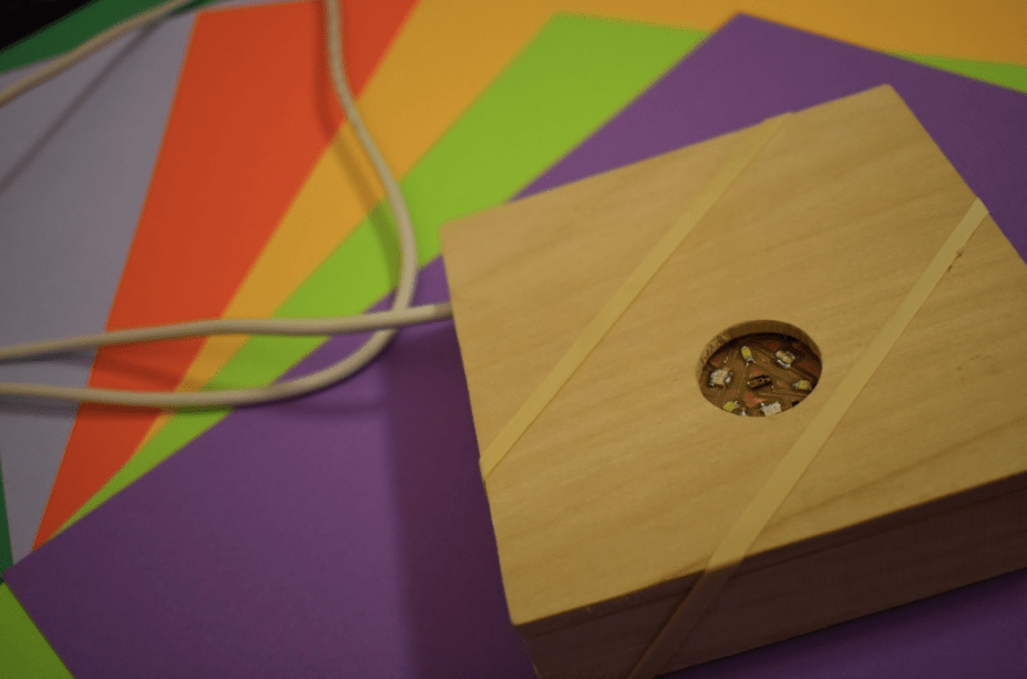
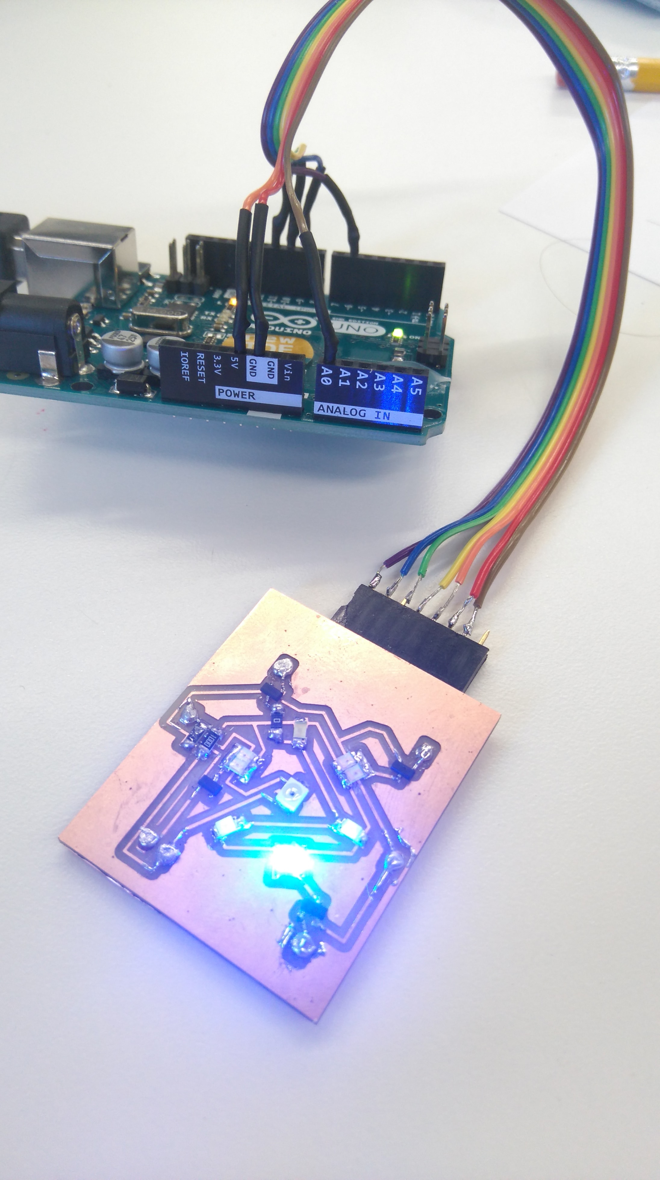
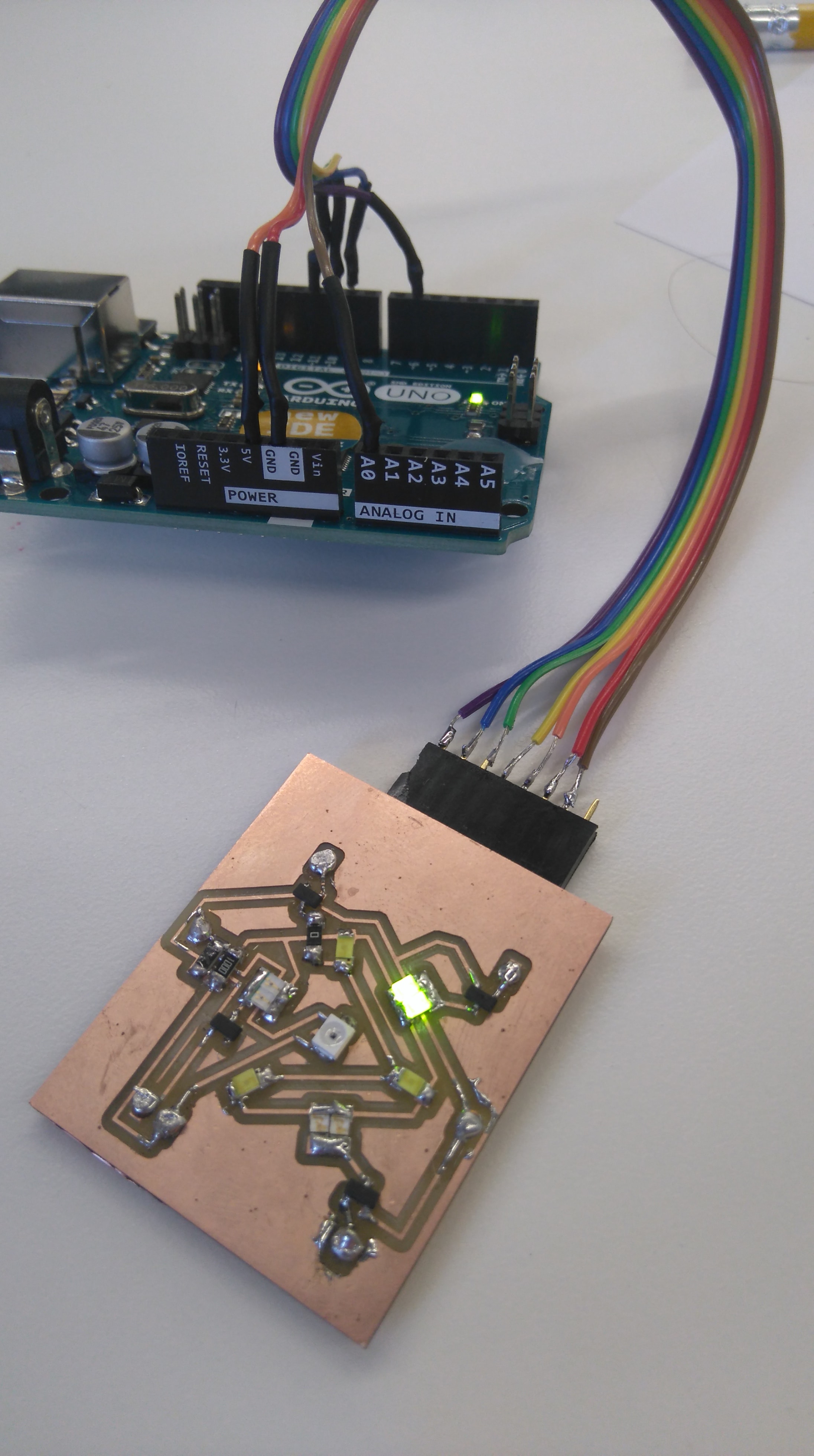
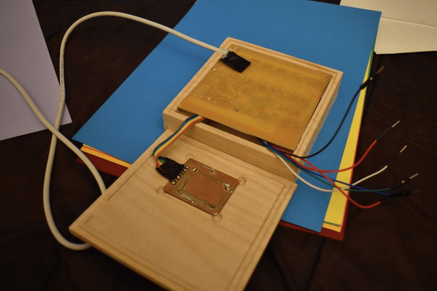
You will need to calibrate the color sensor using a white matte piece of paper - as white reflects 100% of RED, GREEN and BLUE light we will use white to set the maximum values of the value read from the analog pin. I milled a packaging box which you will see in these picture (this is explained in detail below). Firstly place the white paper underneath the box-lid.
Then place the color sensor in the box-lid facing the white paper. Close the box so that background light does not affect the readings.
Run the teston program again - remember to open to serial monitor. You will need to pay attention to the printed values corresponding to step 2), 5), 8) and 11) written above. These values are the highest readings that you should get from the analog pin when the RED, GREEN, BLUE, and WHITE leds are on. Repace the values in the teston code with your ones:

Part of the digit display board was only included for the purpose of loading the arduino bootloader onto the atmega328. I based my design on a Youtube video which said that the following circuit should work:
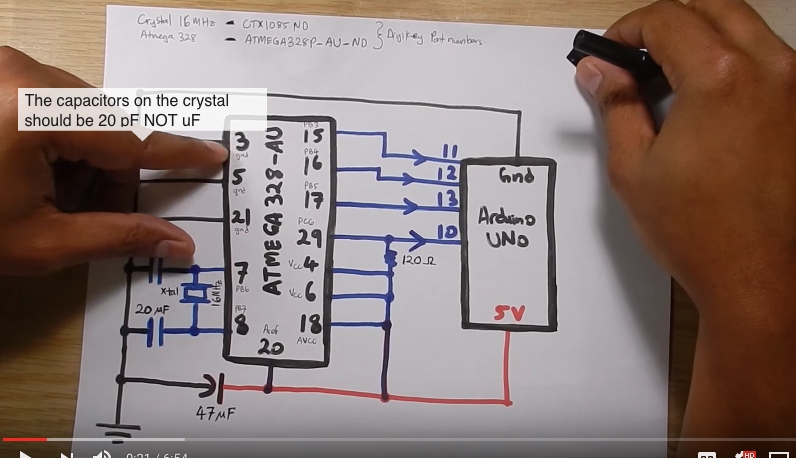
I have highlighted the part of the digit display and atmega328 circuit that is important for loading the arduino bootloader onto the atmega328: Notice that I used a 100 Ohm resistor instead of 120 Ohm (this was because there was no 120 Ohm resistor in the inventory)
To load the arduino bootloader connect arduino to USB port. Open Arduino program, select correct port at tools --> port. Open Arduino ISP sketch under file --> examples -->ArduinoISP. Compile and load sketch onto arduino. Connect the digit-display board to the arduino as shown below:
My setup and pinout is:
Digit-display --> Arduino
RST --> Pin 10
MOSI --> Pin 11
MISO --> Pin 12
SCK --> Pin 13
VCC --> VCC
GND --> GND
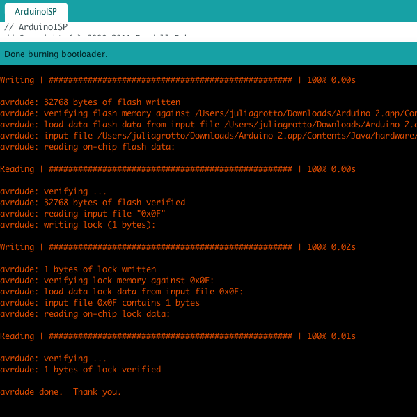
Click on tools --> programmer and choose 'Arduino as ISP.' Check that you have connected the correct pins the select tools --> burn bootloader. If it is successful you should see the message below.
Connect arduino to computer through USB (do not connect anything to arduino yet). Load ArduinoISP sketch onto arduino again. Now connect the digit-display board to the arduino as shown below.
Once again my setup and pinout is:
Digit-display --> Arduino
RST --> Pin 10
MOSI --> Pin 11
MISO --> Pin 12
SCK --> Pin 13
VCC --> VCC
GND --> GND
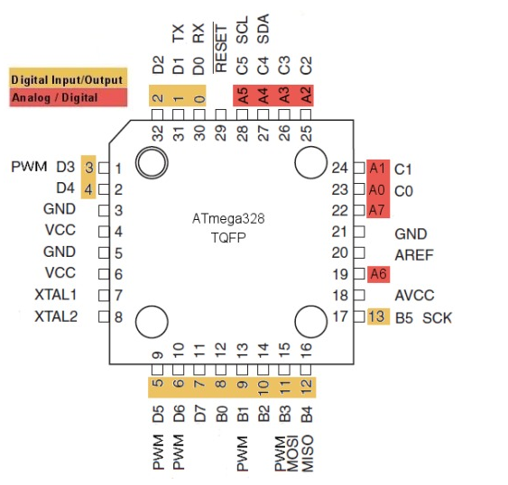
Note: you may notice the pins initialized in the code below do not correspond with the actual pins of the atmega328 in the schematic of my board, but that is because arduino IDE uses a different labling scheme for the chip. This caused me a lot of headaches when nothing was working as it should, but when I figured it out it was really great! The image below illustrates the pinout used by arduino:
Open a new sketch in the arduino program and call it 'TestDisplay'. Copy the following code into it.
/* This program is to test your display. Its a short version of your
 * Original Program and will allow you to investigate the code required
 * to make the display work properly.
 */
int i, j ,y, DIGIT[6] = {6,4,3,2,1,0}, LED[7] = {9,10,A0,7,11,13,12};
String hex[4];                                                          //This array holds the hex numbers that correspond to RED, GREEN, BLUE, WHITE leds respectively.
void setup()
{
  for(i=0;i<6;i++)
  {
    pinMode(DIGIT[i],OUTPUT);                                           //Set all digit pins as output
  }
  for(i=0;i<7;i++)
  {
    pinMode(LED[i],OUTPUT);                                             //Set all led pins as output
  }
}
void loop()
{
 for(i=0;i<6;i++)
  {
      hex[0]="";                                                        //Write in a 2 digit hex number eg. d4 this should appear on the first and second digits of the display
      hex[1]="";                                                        //Write in a 2 digit hex number eg. d4 this should appear on the third and forth digits of the display
      hex[2]="";                                                        //Write in a 2 digit hex number eg. d4 this should appear on the fifth and sixth digits of the display
      digitalWrite(DIGIT[i],HIGH);
      if((i==0)||(i==1)){displayDigit(0,i);}                            //Parse values to displayDigit
      delay(3);
      if((i==2)||(i==3)){displayDigit(1,(i-2));}
      delay(3);
      if((i==4)||(i==5)){displayDigit(2,(i-4));}
      delay(3);
      turnOffLeds();                                                    //Set all pins low before next digit is displayed.
  }
}
Open a new tab in the same sketch call it 'displayDigit' and paste the following code into it:
void displayDigit(int col,int i){
       if(hex[col].charAt(i)=='0')
          {
            digitalWrite(LED[0],HIGH);
            digitalWrite(LED[1],HIGH);
            digitalWrite(LED[2],HIGH);
            digitalWrite(LED[4],HIGH);
            digitalWrite(LED[5],HIGH);
            digitalWrite(LED[6],HIGH);
          }
        if(hex[col].charAt(i)=='1')
          {
            digitalWrite(LED[2],HIGH);
            digitalWrite(LED[5],HIGH);
          }
        if(hex[col].charAt(i)=='2')
          {
            digitalWrite(LED[0],HIGH);
            digitalWrite(LED[2],HIGH);
            digitalWrite(LED[3],HIGH);
            digitalWrite(LED[4],HIGH);
            digitalWrite(LED[6],HIGH);
          }
        if(hex[col].charAt(i)=='3')
          {
            digitalWrite(LED[0],HIGH);
            digitalWrite(LED[2],HIGH);
            digitalWrite(LED[3],HIGH);
            digitalWrite(LED[5],HIGH);
            digitalWrite(LED[6],HIGH);
          }
        if(hex[col].charAt(i)=='4')
          {
            digitalWrite(LED[1],HIGH);
            digitalWrite(LED[2],HIGH);
            digitalWrite(LED[3],HIGH);
            digitalWrite(LED[5],HIGH);
          }
         if(hex[col].charAt(i)=='5')
          {
            digitalWrite(LED[0],HIGH);
            digitalWrite(LED[1],HIGH);
            digitalWrite(LED[3],HIGH);
            digitalWrite(LED[5],HIGH);
            digitalWrite(LED[6],HIGH);
          }
        if(hex[col].charAt(i)=='6')
          {
            digitalWrite(LED[0],HIGH);
            digitalWrite(LED[1],HIGH);
            digitalWrite(LED[3],HIGH);
            digitalWrite(LED[4],HIGH);
            digitalWrite(LED[5],HIGH);
            digitalWrite(LED[6],HIGH);
          }
        if(hex[col].charAt(i)=='7')
          {
            digitalWrite(LED[0],HIGH);
            digitalWrite(LED[2],HIGH);
            digitalWrite(LED[5],HIGH);
          }
        if(hex[col].charAt(i)=='8')
          {
            digitalWrite(LED[0],HIGH);
            digitalWrite(LED[1],HIGH);
            digitalWrite(LED[2],HIGH);
            digitalWrite(LED[3],HIGH);
            digitalWrite(LED[4],HIGH);
            digitalWrite(LED[5],HIGH);
            digitalWrite(LED[6],HIGH);
          }
         if(hex[col].charAt(i)=='9')
          {
            digitalWrite(LED[0],HIGH);
            digitalWrite(LED[1],HIGH);
            digitalWrite(LED[2],HIGH);
            digitalWrite(LED[3],HIGH);
            digitalWrite(LED[5],HIGH);
          }
        if(hex[col].charAt(i)=='a')
          {
            digitalWrite(LED[0],HIGH);
            digitalWrite(LED[1],HIGH);
            digitalWrite(LED[2],HIGH);
            digitalWrite(LED[3],HIGH);
            digitalWrite(LED[4],HIGH);
            digitalWrite(LED[5],HIGH);
          }
        if(hex[col].charAt(i)=='b')
          {
            digitalWrite(LED[1],HIGH);
            digitalWrite(LED[3],HIGH);
            digitalWrite(LED[4],HIGH);
            digitalWrite(LED[5],HIGH);
            digitalWrite(LED[6],HIGH);
          }
        if(hex[col].charAt(i)=='c')
          {
            digitalWrite(LED[0],HIGH);
            digitalWrite(LED[1],HIGH);
            digitalWrite(LED[4],HIGH);
            digitalWrite(LED[6],HIGH);
          }
        if(hex[col].charAt(i)=='d')
          {
            digitalWrite(LED[2],HIGH);
            digitalWrite(LED[3],HIGH);
            digitalWrite(LED[4],HIGH);
            digitalWrite(LED[5],HIGH);
            digitalWrite(LED[6],HIGH);
          }
        if(hex[col].charAt(i)=='e')
          {
            digitalWrite(LED[0],HIGH);
            digitalWrite(LED[1],HIGH);
            digitalWrite(LED[3],HIGH);
            digitalWrite(LED[4],HIGH);
            digitalWrite(LED[6],HIGH);
          }
        if(hex[col].charAt(i)=='f')
          {
            digitalWrite(LED[0],HIGH);
            digitalWrite(LED[1],HIGH);
            digitalWrite(LED[3],HIGH);
            digitalWrite(LED[4],HIGH);
          }

}
Open another new tab in the same sketch call it 'turnOffLeds' and paste the following code into it:
void turnOffLeds(){
       digitalWrite(DIGIT[i],LOW);
       digitalWrite(LED[0],LOW);
       digitalWrite(LED[1],LOW);
       digitalWrite(LED[2],LOW);
       digitalWrite(LED[3],LOW);
       digitalWrite(LED[4],LOW);
       digitalWrite(LED[5],LOW);
       digitalWrite(LED[6],LOW);
}
Now load this sketch onto the ATMEGA328 using the arduino as the program - you can do this by selecting Sketch --> Upload using programmer. After it has uploaded you should see the display show the hex numbers that you typed into code.
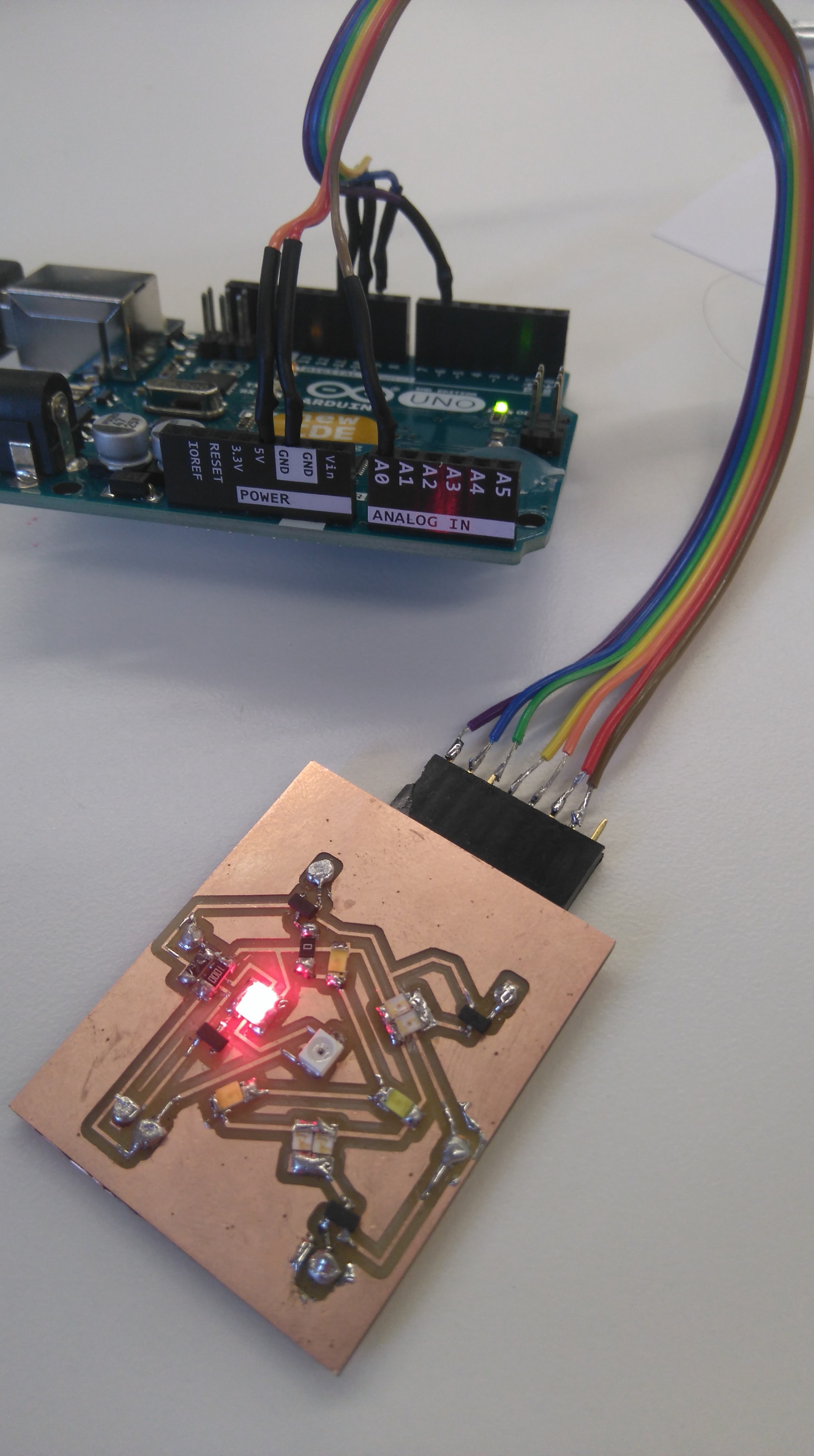
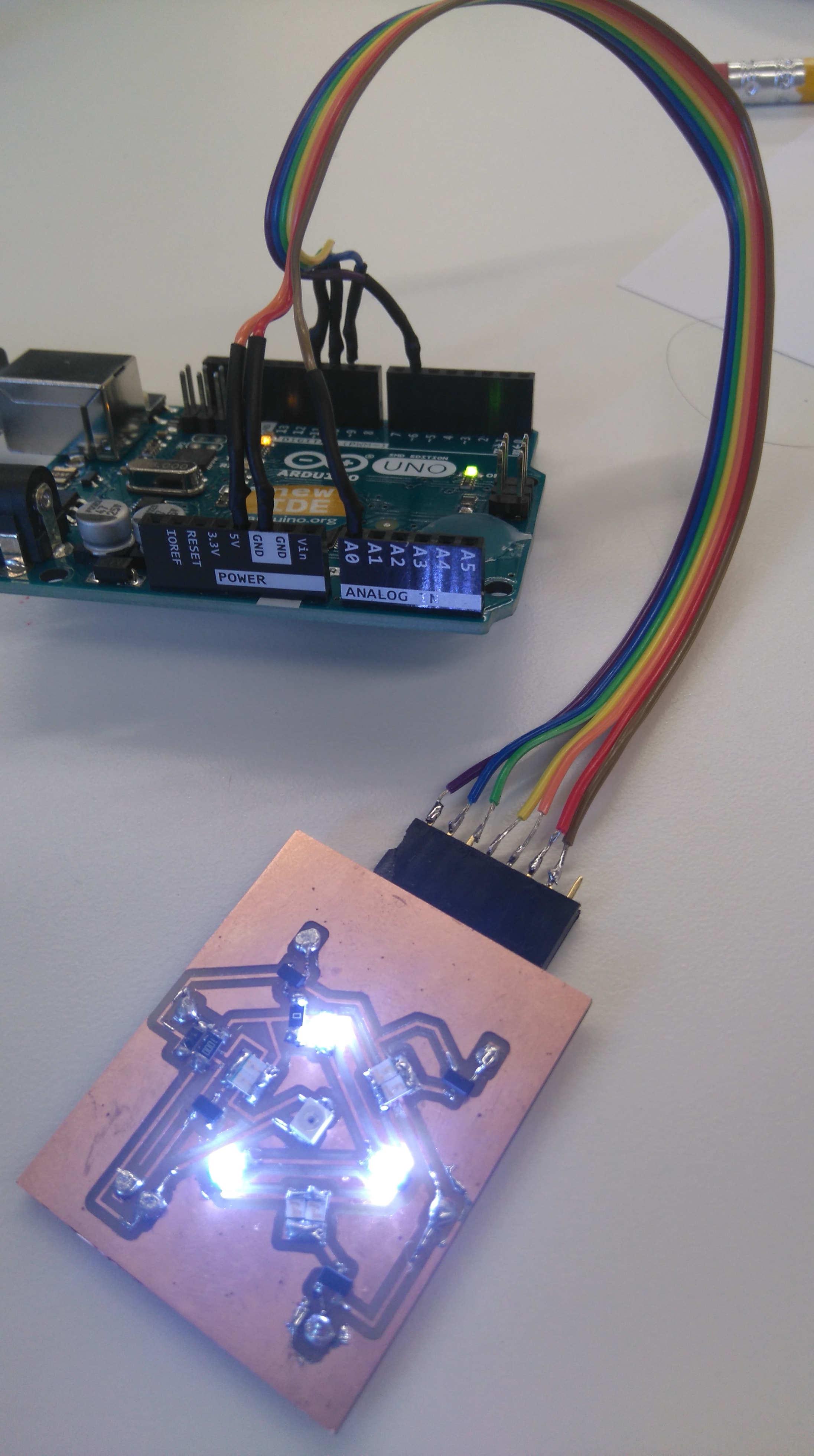
Connect arduino to the computer through USB (do not connect anything to the arduino yet). Load ArduinoISP sketch onto the arduino again. Now connect the digit-display board to the arduino and the color sensor to the digit display board as shown below:
Create another new sketch called 'testcolorsensor' and copy the following code into it:
int i, j ,y, COLORSENSOR[5] = {A5,A4,A3,A1}, DIGIT[6] = {6,4,3,2,1,0}, LED[7] = {9,10,A0,7,11,13,12};   // DECLARE  R   G   B  PINS
float readValue[100];
float averagereadmap[4];
float averageread[4]={0,0,0,0};
long inthex[4];
String hex[4];
void setup()
{
  setupAllPins();
  readAndCalculateAverage();
}
void loop()
{
  for(i=0;i<6;i++)
  {
      digitalWrite(DIGIT[i],HIGH);
      if((i==0)||(i==1)){displayDigit(0,i);}
      if((i==2)||(i==3)){displayDigit(1,(i-2));}
      if((i==4)||(i==5)){displayDigit(2,(i-4));}
      turnOffLeds();
  }
}
Open another new tab in the same sketch call it 'digitDisplay' and paste the following code into it:
void displayDigit(int col,int i){
       if(hex[col].charAt(i)=='0')
          {
            digitalWrite(LED[0],HIGH);
            digitalWrite(LED[1],HIGH);
            digitalWrite(LED[2],HIGH);
            digitalWrite(LED[4],HIGH);
            digitalWrite(LED[5],HIGH);
            digitalWrite(LED[6],HIGH);
          }
        if(hex[col].charAt(i)=='1')
          {
            digitalWrite(LED[2],HIGH);
            digitalWrite(LED[5],HIGH);
          }
        if(hex[col].charAt(i)=='2')
          {
            digitalWrite(LED[0],HIGH);
            digitalWrite(LED[2],HIGH);
            digitalWrite(LED[3],HIGH);
            digitalWrite(LED[4],HIGH);
            digitalWrite(LED[6],HIGH);
          }
        if(hex[col].charAt(i)=='3')
          {
            digitalWrite(LED[0],HIGH);
            digitalWrite(LED[2],HIGH);
            digitalWrite(LED[3],HIGH);
            digitalWrite(LED[5],HIGH);
            digitalWrite(LED[6],HIGH);
          }
        if(hex[col].charAt(i)=='4')
          {
            digitalWrite(LED[1],HIGH);
            digitalWrite(LED[2],HIGH);
            digitalWrite(LED[3],HIGH);
            digitalWrite(LED[5],HIGH);
          }
         if(hex[col].charAt(i)=='5')
          {
            digitalWrite(LED[0],HIGH);
            digitalWrite(LED[1],HIGH);
            digitalWrite(LED[3],HIGH);
            digitalWrite(LED[5],HIGH);
            digitalWrite(LED[6],HIGH);
          }
        if(hex[col].charAt(i)=='6')
          {
            digitalWrite(LED[0],HIGH);
            digitalWrite(LED[1],HIGH);
            digitalWrite(LED[3],HIGH);
            digitalWrite(LED[4],HIGH);
            digitalWrite(LED[5],HIGH);
            digitalWrite(LED[6],HIGH);
          }
        if(hex[col].charAt(i)=='7')
          {
            digitalWrite(LED[0],HIGH);
            digitalWrite(LED[2],HIGH);
            digitalWrite(LED[5],HIGH);
          }
        if(hex[col].charAt(i)=='8')
          {
            digitalWrite(LED[0],HIGH);
            digitalWrite(LED[1],HIGH);
            digitalWrite(LED[2],HIGH);
            digitalWrite(LED[3],HIGH);
            digitalWrite(LED[4],HIGH);
            digitalWrite(LED[5],HIGH);
            digitalWrite(LED[6],HIGH);
          }
         if(hex[col].charAt(i)=='9')
          {
            digitalWrite(LED[0],HIGH);
            digitalWrite(LED[1],HIGH);
            digitalWrite(LED[2],HIGH);
            digitalWrite(LED[3],HIGH);
            digitalWrite(LED[5],HIGH);
          }
        if(hex[col].charAt(i)=='a')
          {
            digitalWrite(LED[0],HIGH);
            digitalWrite(LED[1],HIGH);
            digitalWrite(LED[2],HIGH);
            digitalWrite(LED[3],HIGH);
            digitalWrite(LED[4],HIGH);
            digitalWrite(LED[5],HIGH);
          }
        if(hex[col].charAt(i)=='b')
          {
            digitalWrite(LED[1],HIGH);
            digitalWrite(LED[3],HIGH);
            digitalWrite(LED[4],HIGH);
            digitalWrite(LED[5],HIGH);
            digitalWrite(LED[6],HIGH);
          }
        if(hex[col].charAt(i)=='c')
          {
            digitalWrite(LED[0],HIGH);
            digitalWrite(LED[1],HIGH);
            digitalWrite(LED[4],HIGH);
            digitalWrite(LED[6],HIGH);
          }
        if(hex[col].charAt(i)=='d')
          {
            digitalWrite(LED[2],HIGH);
            digitalWrite(LED[3],HIGH);
            digitalWrite(LED[4],HIGH);
            digitalWrite(LED[5],HIGH);
            digitalWrite(LED[6],HIGH);
          }
        if(hex[col].charAt(i)=='e')
          {
            digitalWrite(LED[0],HIGH);
            digitalWrite(LED[1],HIGH);
            digitalWrite(LED[3],HIGH);
            digitalWrite(LED[4],HIGH);
            digitalWrite(LED[6],HIGH);
          }
        if(hex[col].charAt(i)=='f')
          {
            digitalWrite(LED[0],HIGH);
            digitalWrite(LED[1],HIGH);
            digitalWrite(LED[3],HIGH);
            digitalWrite(LED[4],HIGH);
          }
}
Open another new tab in the same sketch call it 'readAndCalculateAverage' and paste the following code into it:
void readAndCalculateAverage(){
    for(j = 0 ; j < 4 ; j++)                    //  CYCLE  PINS
    {
      digitalWrite(COLORSENSOR[j],HIGH);
      delay(100);
      for(i=0 ; i<100 ; i++)
      {
        readValue[i] = analogRead(A2);
        delay(10);
        averageread[j] = averageread[j]+readValue[i];
      }
      digitalWrite(COLORSENSOR[j],LOW);
      averageread[j] =averageread[j]/100;
      if     (j==0) { scaleAndProduceHexString(0, 911);} //Red
      else if(j==1) { scaleAndProduceHexString(1,  991);} //Blue
      else if(j==2) { scaleAndProduceHexString(2, 659);} //Green
      else          { scaleAndProduceHexString(3, 980);} //White
    }
}
Open another new tab in the same sketch call it 'scaleAndProduceHexString' and paste the following code into it:
void scaleAndProduceHexString(int col, int scale){
  averagereadmap[col]=map(averageread[col],0,scale,0,255);
  averagereadmap[col]=constrain(averagereadmap[col],0,255);
  Serial.print(averagereadmap[col]);
  Serial.print('\n');
  inthex[col] = averagereadmap[col];
  hex[col] = String(inthex[col],HEX);
  if (hex[col].length()==1)
  {
    hex[col] = '0'+ hex[col];
  }
  Serial.print(hex[col]);
  Serial.print('\n');
}
Open another new tab in the same sketch call it 'setupAllPins' and paste the following code into it:
void setupAllPins(){
  for(i=0; i<4; i++)
  {
    pinMode(COLORSENSOR[i],OUTPUT);
  }
  for(i=0; i<6; i++)
  {
    pinMode(DIGIT[i],OUTPUT);
  }
  for(i=0; i<7; i++)
  {
    pinMode(LED[i],OUTPUT);
  }
  //pinMode(analogPin,INPUT);
  delay(1000);
  for(i=0; i<6; i++)
  {
    digitalWrite(DIGIT[i],LOW);
  }
  for(i=0; i<7; i++)
  {
    digitalWrite(LED[i],LOW);
  }
  for(i=0; i<4; i++)
  {
   digitalWrite(COLORSENSOR[i],LOW);
  }
}
Open another new tab in the same sketch call it 'turnOffLeds' and paste the following code into it:
void turnOffLeds(){
       digitalWrite(DIGIT[i],LOW);
       digitalWrite(LED[0],LOW);
       digitalWrite(LED[1],LOW);
       digitalWrite(LED[2],LOW);
       digitalWrite(LED[3],LOW);
       digitalWrite(LED[4],LOW);
       digitalWrite(LED[5],LOW);
       digitalWrite(LED[6],LOW);
}
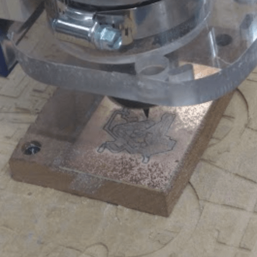
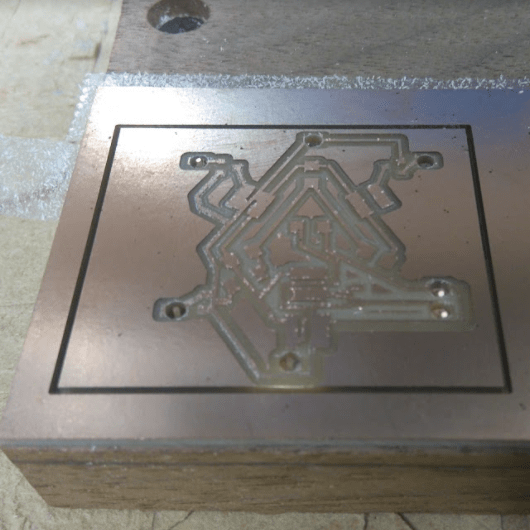
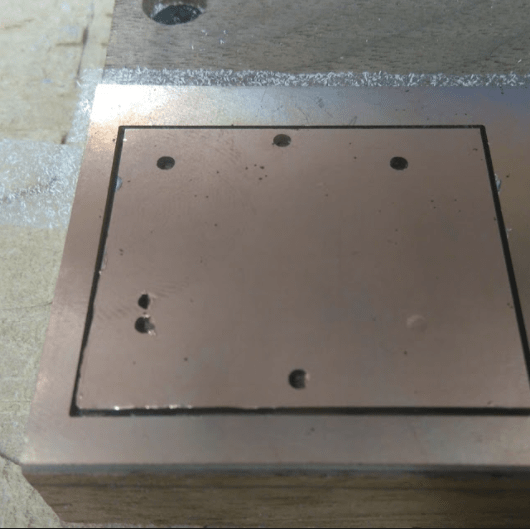
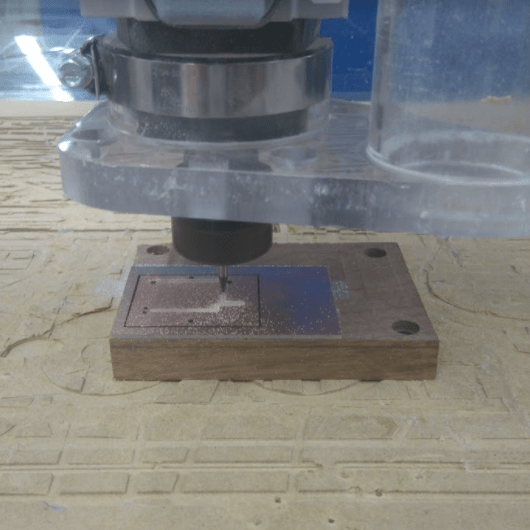
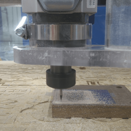
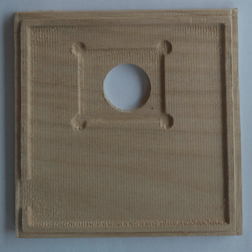
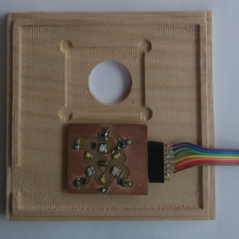
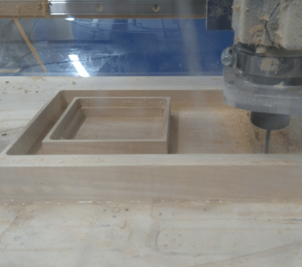
I designed the packaging in Fusion360. I exported to stl by right clicking on component and selecting 'save to stl'. The design below will be the wooden box to hold my electronics.
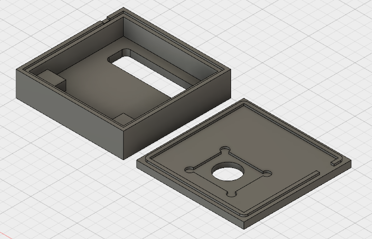
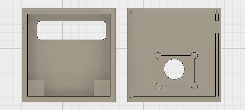
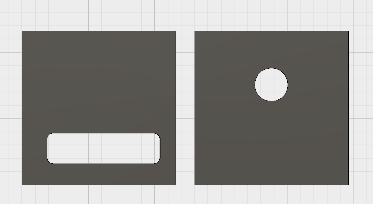
I bought a piece of wood from Dickson Bros for $15 - I had to go for a size much larger than needed due to the restriction of sizes available. I decided to mill my box from the wood-block (which in retrospect was a crazy plan.) I uploaded my 3D stl design into a new PartWorks file. The material dimensions were about double my required dimensions for the box. Before milling out the box I decided to remove 3/4" off the top of the wood with a 1/2" mill this would decrease the mill time of the model. I saved the rough-cut and finishing cut files that PartWorks created, setup my wood-block on the stage of the mill and began milling. OH MY GOODNESS!!!! IT WAS SO SO SO LOUD!!!! After an hour I held in my hand my box - but was it worth the time and noise? Probably not, next time I will do something press-fit...
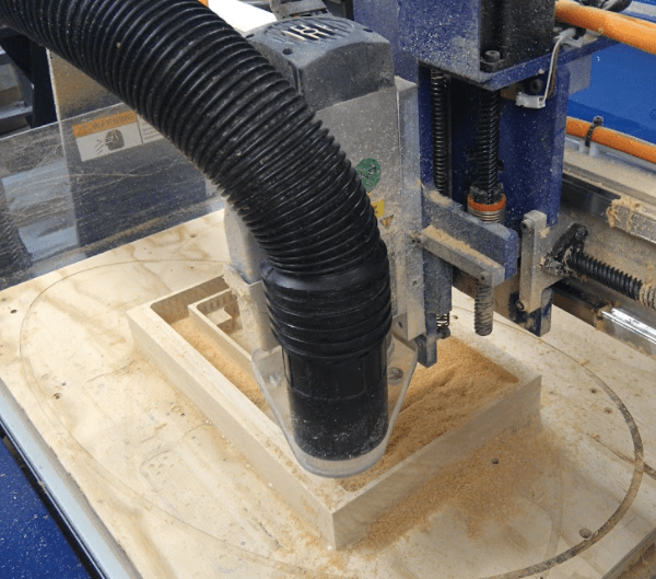
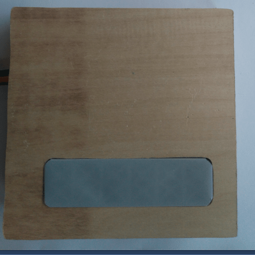
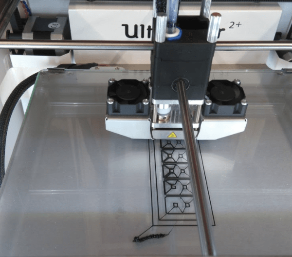
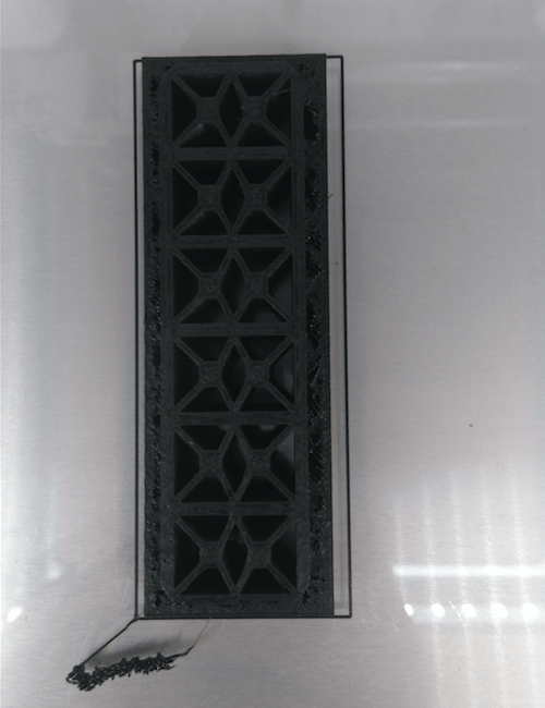
I designed a 3D print component that would fit into the rectangular hole in the box. This part's function is to guide the light of the leds on the display and make the digits more legible.
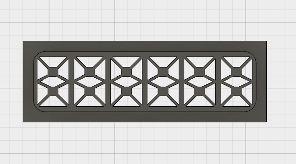
I uploaded the stl file into Cura and optimized the orientation before saving to the SD card. The print took about one hour and 30 minutes, but the final product was well worth it!
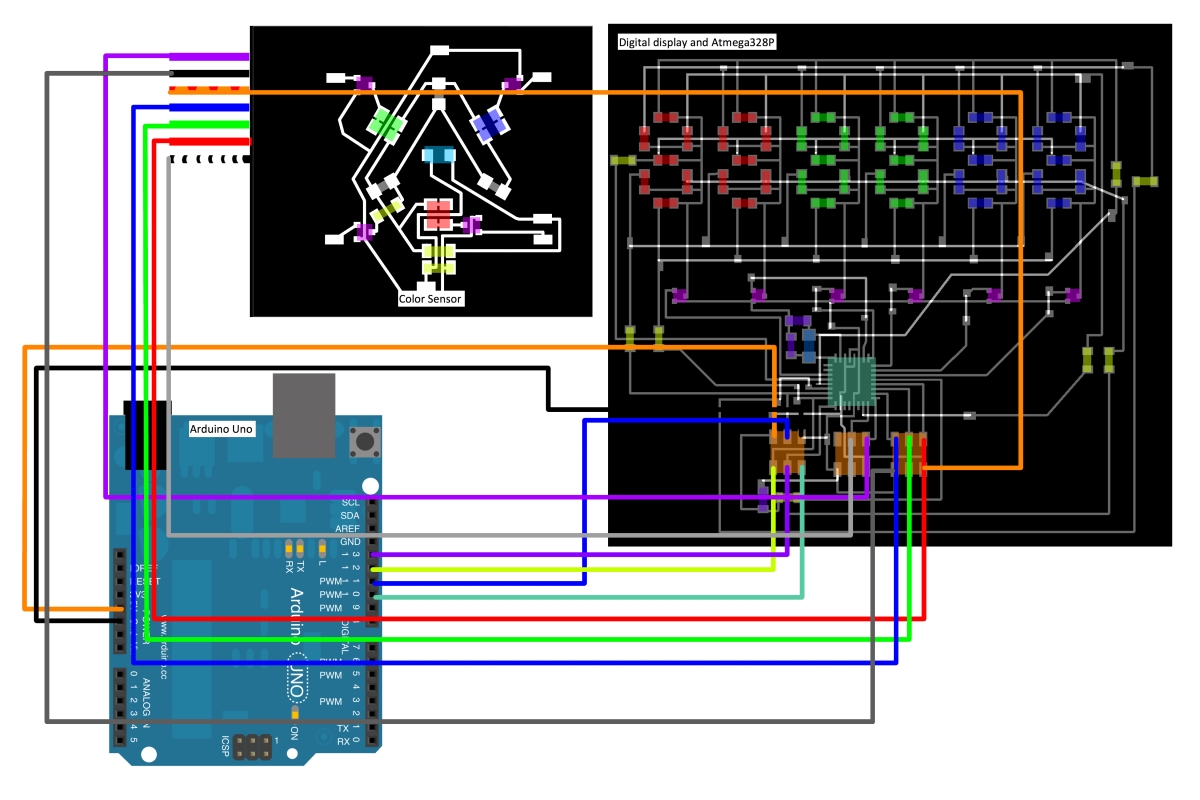
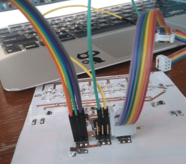
The wires I was using for testing were much to big to all fit into the box, and so I rewired the circuit boards together more permanently and efficiently. I left wires to reprogram the board in case something went wrong. Below you can see the old and new wiring:
Here are some pictures of my tests to check that my calibration was accurate:
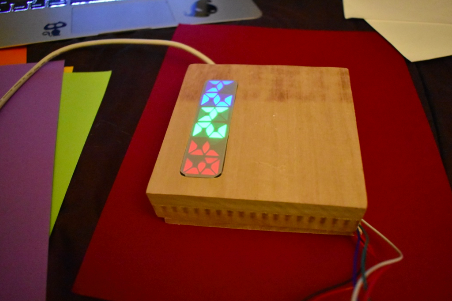
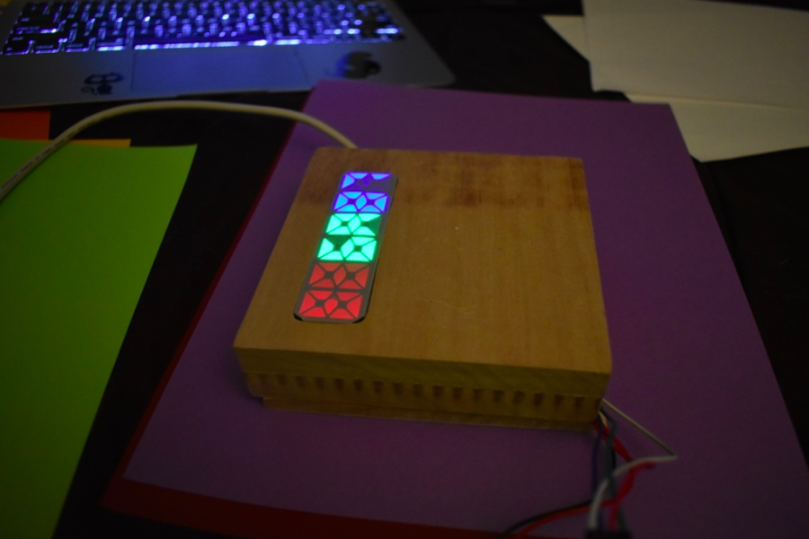
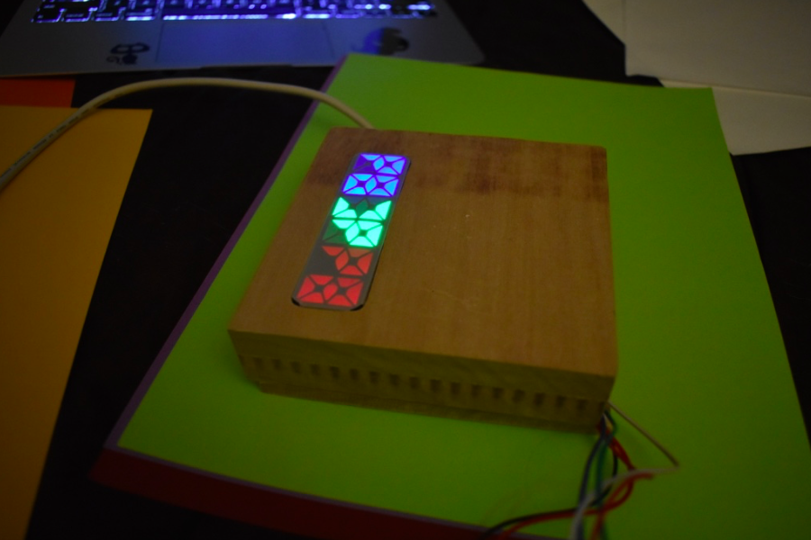
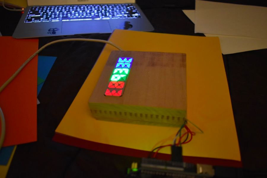
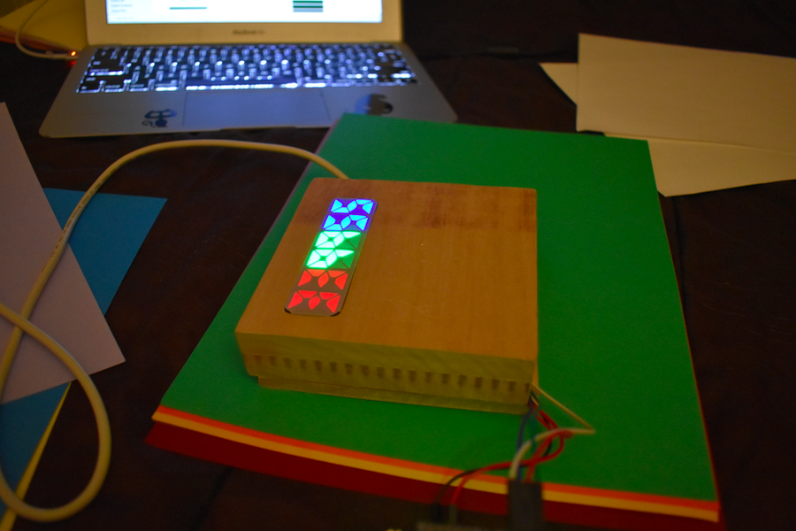
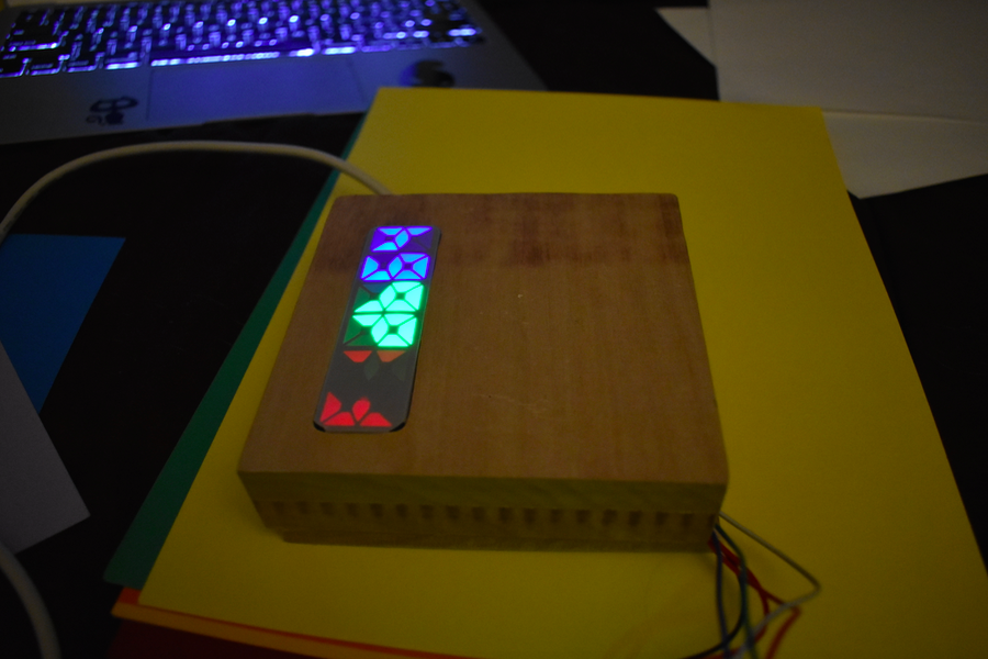
The final product: