
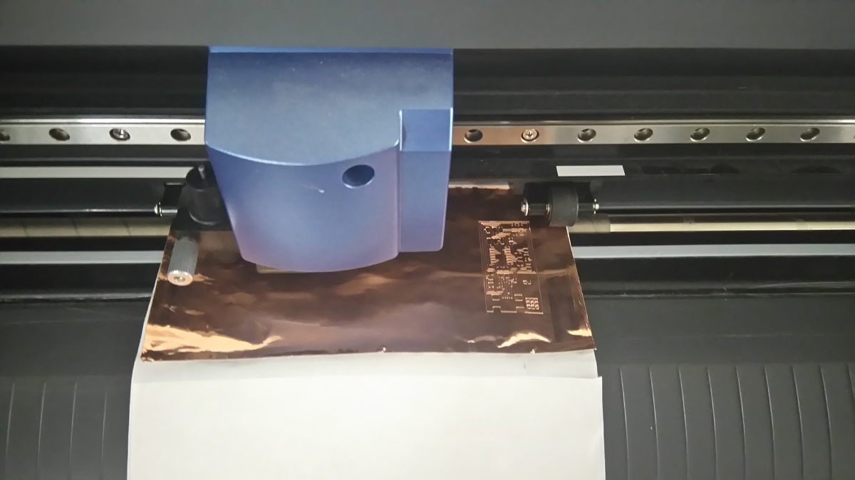
Flexible Circuits! Oh my goodness I had never thought about vinyl cutting copper before. Whilst I wait for some time on the mill I am going to try out the vinyl cutter.
Tips on cutting copper:
1) The copper traces are quite narrow and so to get a clean cut I should re-stick the copper to an epoxy film. Sticky side of the copper should be applied to sticky side of the epoxy. Apparently the cutting process may kick up some of the traces if the copper is cut when it is still on its original substrate.
2) Use a smaller force than for cutting vinyl - I am going to used a force of 75g.
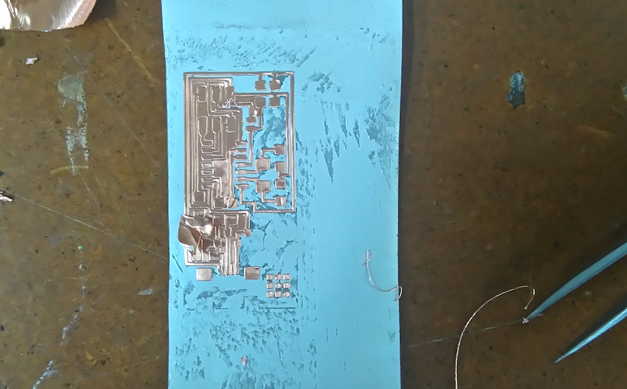
Okay - now for the finicky part: Removing excess copper.
The epoxy backing has definitely provided a secure base for the copper traces, but it has also provided a pretty strong hold on the excess copper. A mix of tweezers, patience and focus is so far successfull in doing the job. Just gotta keep going.
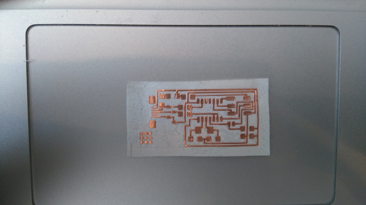
Okay - ALL DONE.
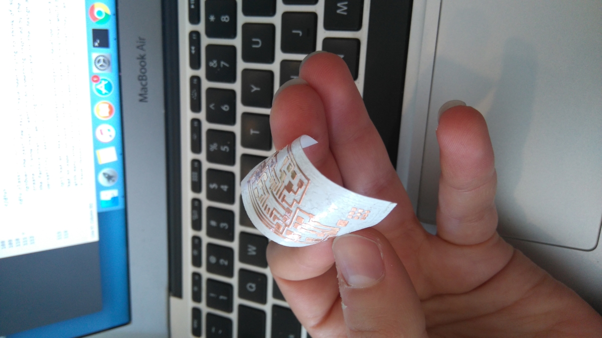
It is FLEXIBLE!
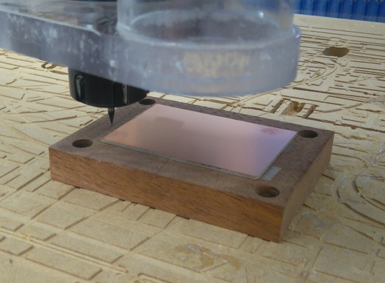
There is still a long line for the Roland Modela - so I am going to train on the ShopBot as well. The step by step process to use the machine goes:
1) Make sure the activation key for the machine is disengaged.
2) Remove the shield.
3) Mount the copper plated substrate on the stage. (use double stick tape - make sure that there are no bubbles as they will cause the plate to not be level and the procedure may fail as a result)
3) Install the 1/32 mill tip - take care not to drop it. Tighten the screw lock until snug. The mill tip should be about 5mm from the top of the copper plated substrate so as to avoid bumping into the stage and breaking the tip.
4) Use the control panel on the computer to move the mill to the middle of the substrate.
5) Losen the screw lock and carefully lower the mill tip until it touches the surface of the copper. Tighten screw lock once more.
6) The tip will have lifted a bit when tightening the hold - the control panel should be used to lower the tip until it touches the copper once more. Use increments of 0.01mm in z to lower the tip slowly.
7) Zero z axis on control panel.
8) Move the tip up about 1mm in z. Move the tip to the origin of the x-y plane - this should be close to the bottom left corner of the substrate.
9) Zero x and y axis in the control panel.
10) IMPORTANT: Close yellow control panel.
11) Remount the shield.
12) Re-ingage the activation key.
13) Open fabmodules and input file.
14) Type in correct specifications for cut depth etc.
15) Save file to destop
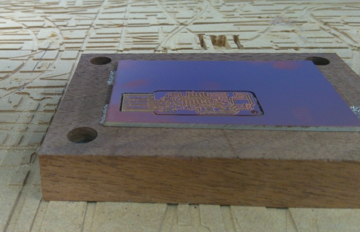
16) On red control panel click the button 'cut part' - then open the file that you saved to the desktop and start milling!
I have never soldered before, so here goes.... I am going to do some practice soldering first on some failed boards.
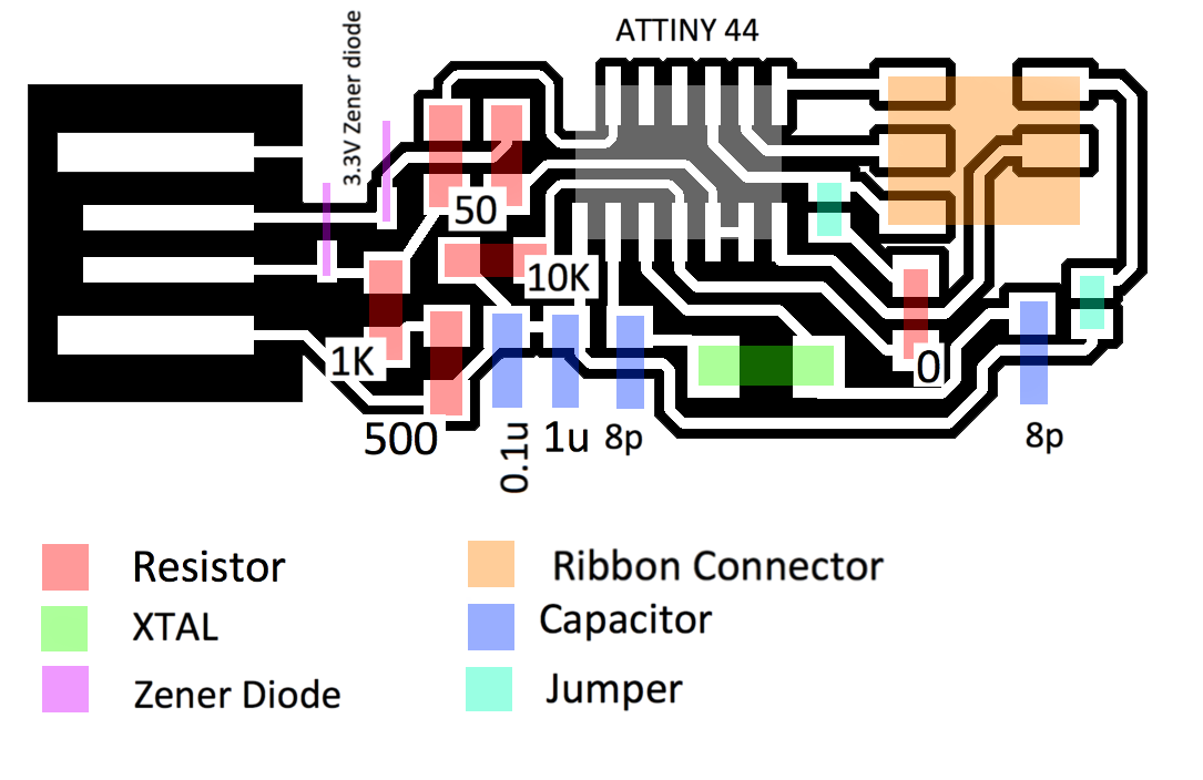
I was unable to find an unpdated version of the schematic with lables of the parts. I did my best with the documentation on the wedsite and made an image illustrating my result.
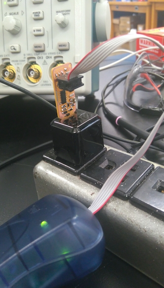
I got completely absorbed in soldering my board and forgot to take pictures, anyway here is the end product. Notice how I have supplemented the copper USB traces with some solder - this will allow for a better connection. Also notice the jumper connections made with solder.
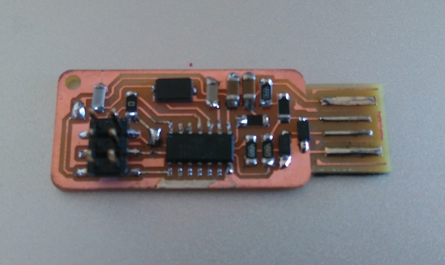
The board has passed the initial testing - using a multimeter to check that the traces and solder connections are correct. I have also uploaded the program onto it using another programer.
.