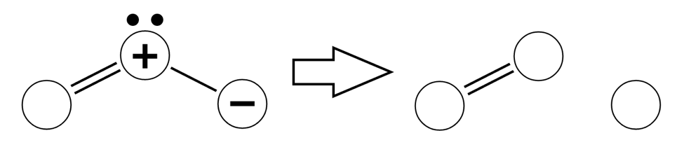
Ozone is an unstable molecular gas comprised of three oxygen atoms. The molecule quickly degrades to an oxygen diatomic molecule and a free radical. The free radical atom is very reactive and is responsible for the purification potential of Ozone.
The decomposition of Ozone depends on several factors:
1 The fluid in which Ozone is dispersed:
- Ozone has a much longer half-life in air than in water.
2 Temperature:
- With an increase of 10 degrees celsius the half-life decreases by 20%-30%
3 pH:
- Basic environments have a greater concentration of Hydroxide radicals. These radicals partly decompose ozone (they are initiators of the decomposition reaction). Therefore, ozone decays much faster in basic environments than acidic environments.
4 Concentration of impurities in fluid:
- Ozone eradicates bacteria, viruses, it also oxidizes iron, manganese, sulfur to form insoluble oxides which can be removed by filtering the water.
In nature it is produced either by the corona discharge of lightning, or by ultra-violet sun rays. In order to produce ozone in the lab, dry air is passed through a region of high potential difference (produced by conductive plates with a voltage difference between them). A concentration of 1-3% ozone can be produced from air; higher concentrations are obtained when pure oxygen is used. The root mean square voltages used range from 7-30 kV and the frequencies of the alternating voltage ranges from 60Hz to 4000Hz. Lower voltages and higher frequencies reduce the occurrence of arcs between plates and increase the production of ozone. The current and the waveform must also be taken into consideration as these also affect production of ozone.
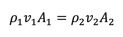
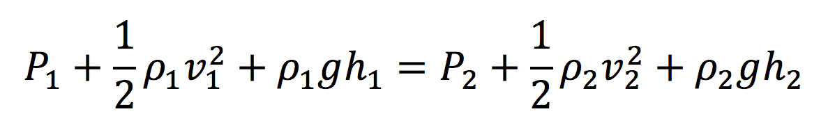
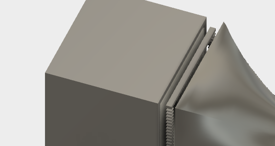
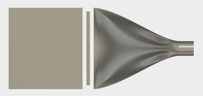
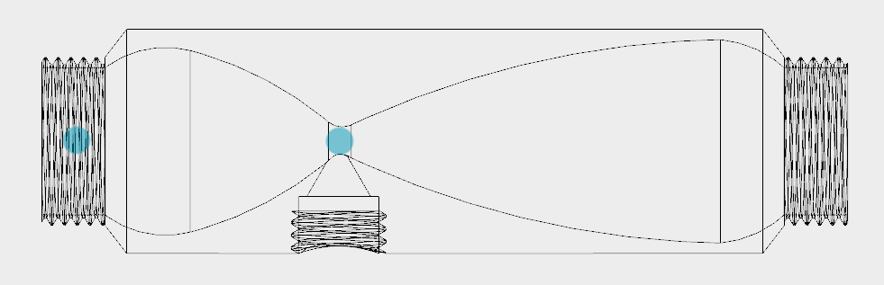
Venturi Injector – this simple device uses the conservation of mass theory and the Bernoulli equation to control the pressure changes of the fluid as it passes through the device. The point of injection of ozone occurs at the point where the pressure of the fluid drops thus creating a vacuum which pulls the ozone into the fluid.
I have begun by making a 3D representation of a venturi injector in fusion 360. The concept is that at the point of injection the pressure in the water will have dropped low enough to open the one-way valve and suck ozone into the water.
computer controlled machining – to construct iron core for motor electromagnet from a sheet of iron.
circuit design, manufacture and embedded programing – to create an interface for the purifier by which users can start, stop and calculate volume of purified water etc…
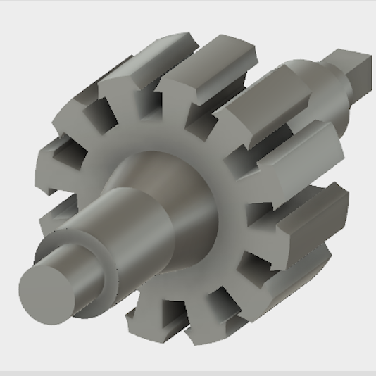
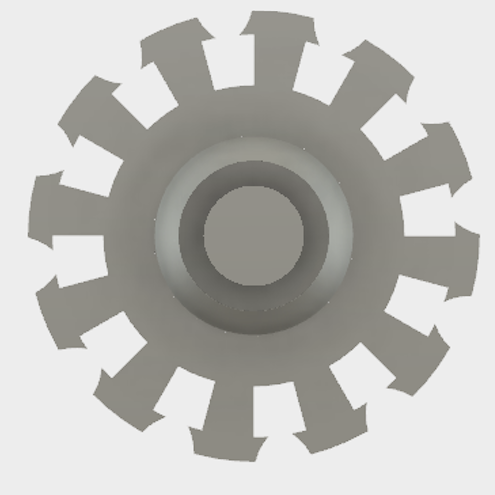
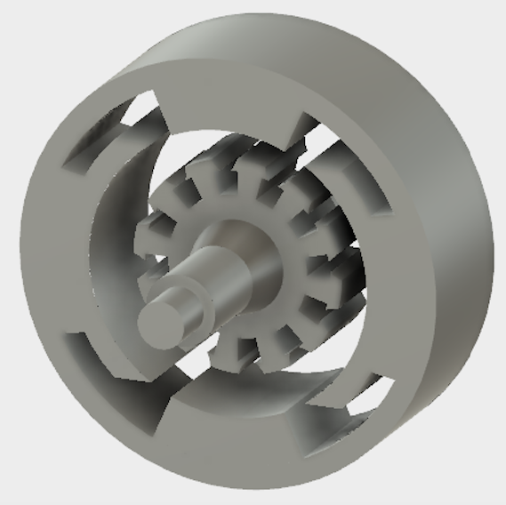
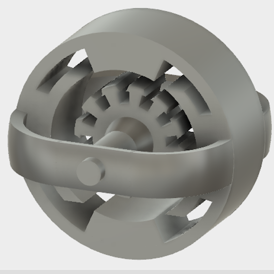
3D printing – to print motor structure which supports moving coils, to print the propeller as well as a system of cogs, to print the enclosed structure for the ozone generator and to print the venture injector.
vinyl cutting and molding and casting – to cut the copper plates that connect to the moving coils and the brushes in the motor.

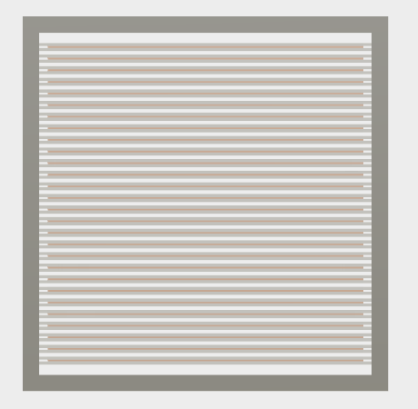
I have decided to use the technique of creating a strong electric field between charged plates to ozonate the airflow. In order to reduce the likelihood of electric breakdown or sparks between plates of copper – they are going to be covered on both sides with thin panes of glass. These glass-copper-glass sandwiches are going to be stacked with a gap of 1mm between them to a height of about 100mm. The stack of alternating charged plates are going to be enclosed in a box which guides air into and out of the ozone generating zone.
Here is one glass-coppoer-glass set seen from above.

The full stack.

The casing for the stack of charged plates.
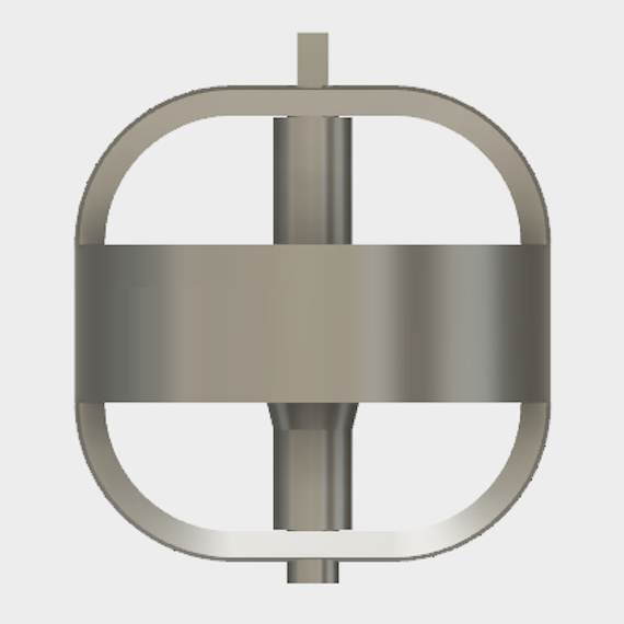
The air will be sucked into the generator by a fan which will be connected to a motor. The motor consists of a central structure that will support the coils of copper wire – the central structure will be placed inside a ‘constant’ electric field produced by two loops of wire – one to the right and one to the left.


I will need to create a couple of different circuits that will perform different functions:
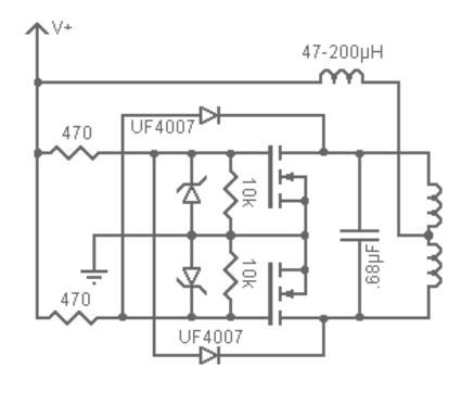
1) ZVS Driver - This circuit creates AC from DC which I will need for the step up transformer. It is also very efficient at oscillating a large amount of power. This circuit leads to a resonant rise of the input voltage by a factor of pi, but I will still neet a step-up transformer to increave voltage to about 1kV.
2) Sensor Circuits - I will need pressure sensors and heat sensors.
The pressure sensors will allow me to measure the water pressure at two points shown by jade dots on the image below (the water inlet of the venturi injector as well as the point of ozone injection.) I need to make sure that the pressure drop will be sufficient to suck ozone through the one way valve.
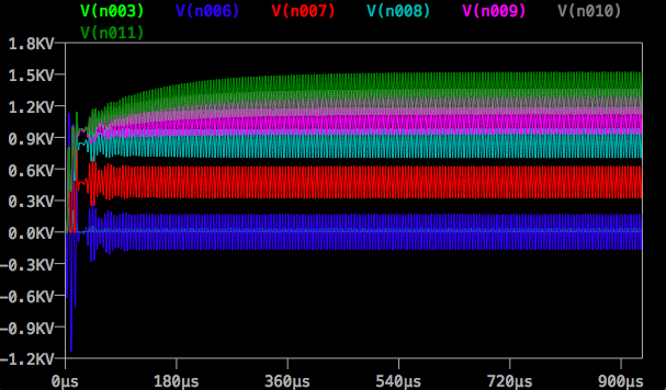
I have tested the circuit in LTSpice. LTSpice is a circuit simulation program which allows me to visualize the Voltage at different points in the circuit. Below is a screenshot of both the circuit and the Voltage measurements taken at different points in the circuit. The points of the circuit at which the voltage has been measured are indicated by coloured dots. The colours correspond to the Voltage line graph colours.
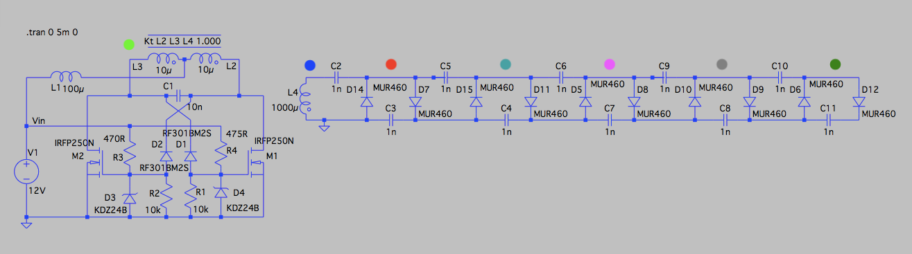
The visualization confirms several predictions:
1) There is a resonant rise in the voltage in the ZVS driver circuit from 12V input to about 80 peak voltage.
2) The output voltage of the ladder oscillates around 1.3kV.
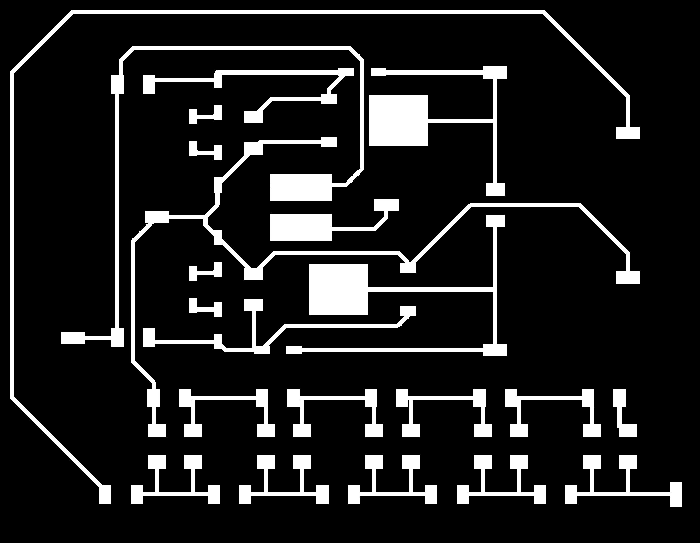
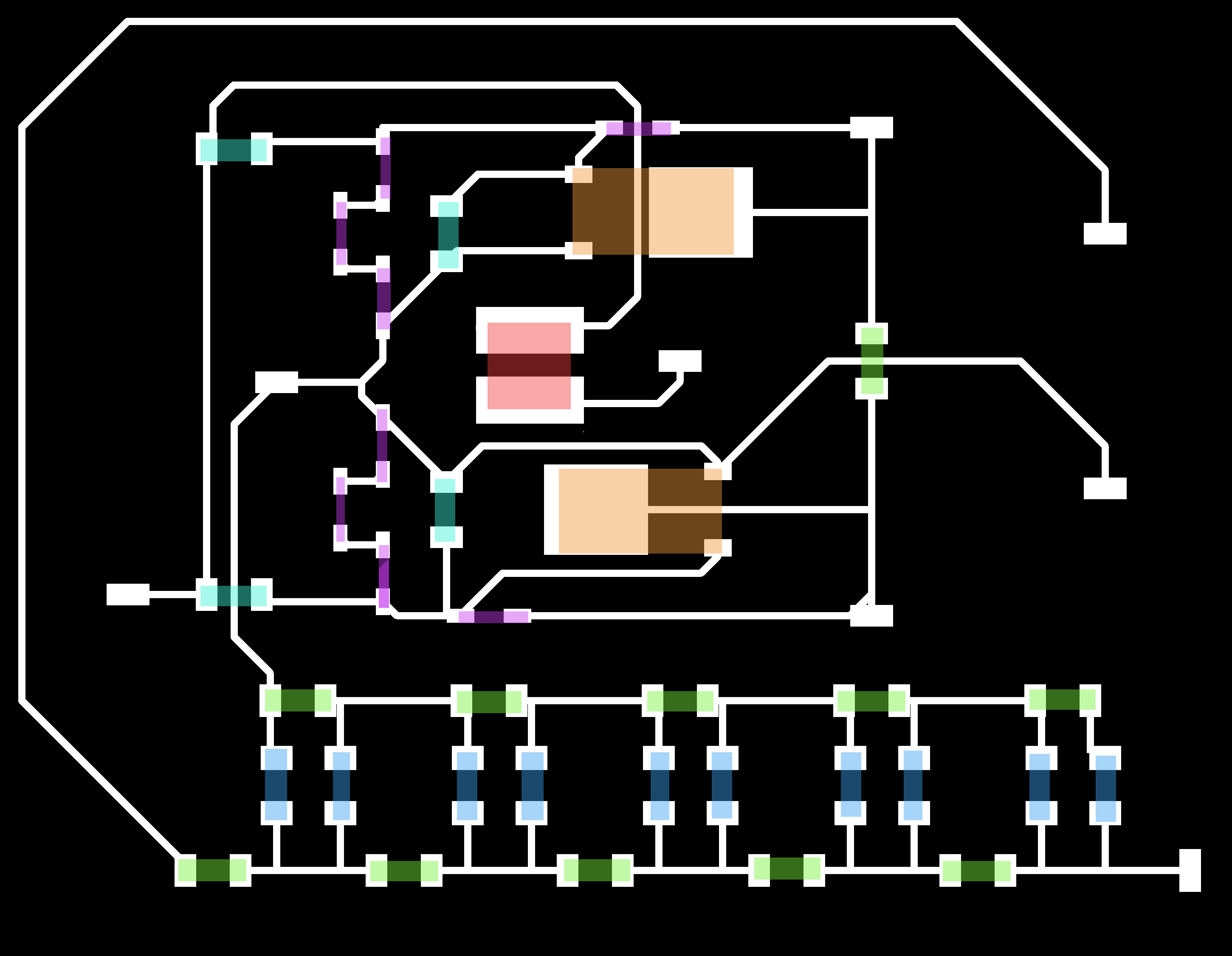
Designing and milling circuits:
I recreated the circuit in Eagle PCB and routed to board. The colour coding for the components is:
Blue and Purple - Diode
Green - Capacitor
Jade - Resistor
Red - Inductor
Orange - Mosfet
The ZVS design is based off the design shown above.
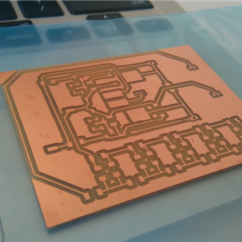
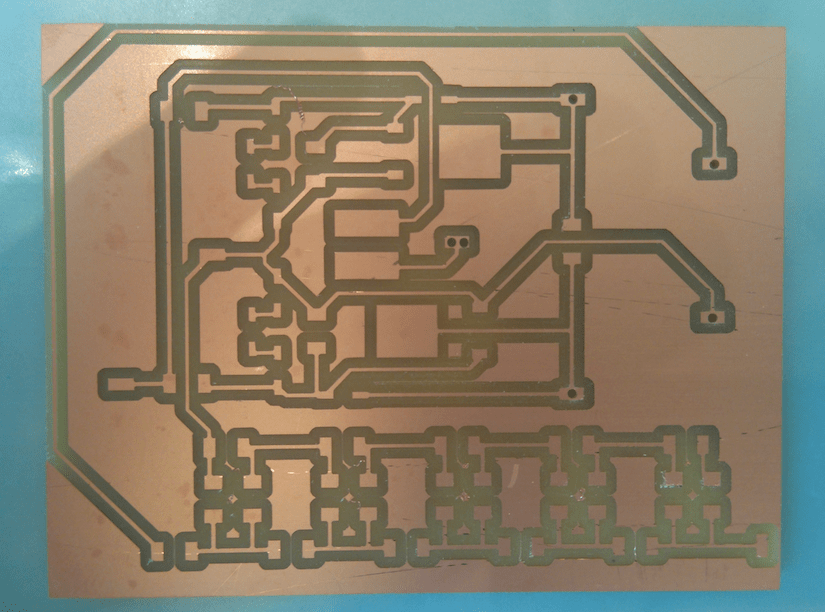
Here are pictures of the milled board.
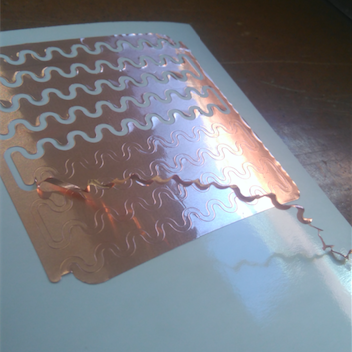
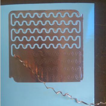
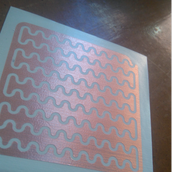
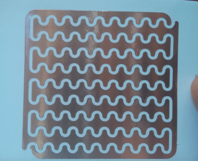
Designing and vinyl cutting copper plates:
Initially I was going to do layers of alternating charged plates as shown above, but I have decided to try something a little different - I designed in Fusion360 interlocking plates. Using the vinyl cutter would give me some control over the space between the positively and the negatively charged plates. This gap should be a reflection of the Voltage across the plates and the breakdown distance of air.