
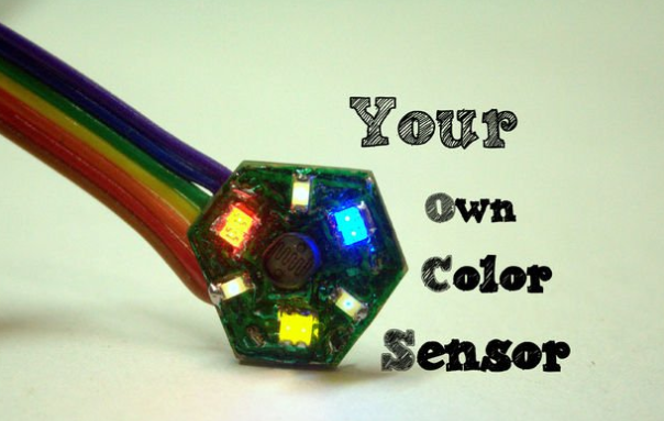
I spent quite a while thinking about what I would like to do this week. After a couple of hours of internet research, I came across a design for a color sensor on Instructables. I had to modify the design because we did not have all the components in the fab inventory.
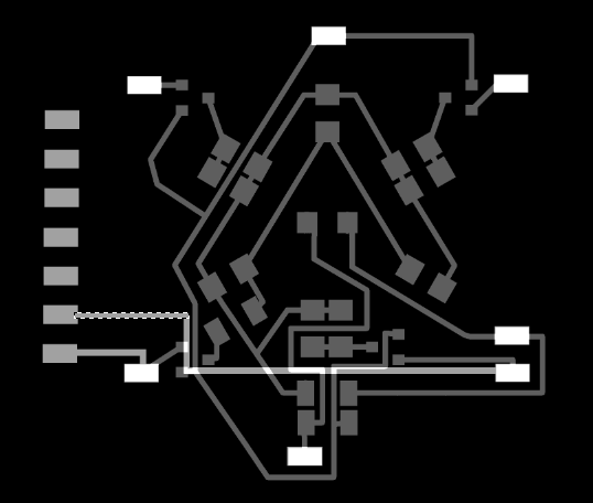
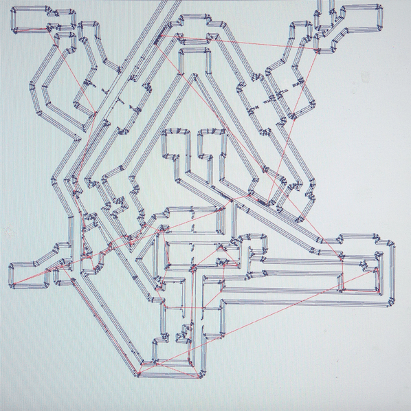
I used Eagle to create the PCB design below:
The board is designed to be double sided, but I was not too sure how to do the in eagle – will need to figure that out – and so I used GIMP to manually draw out the bottom layer. As the bottom layer was not very complicated it did not take too much time to route it by hand.
Tips on using GIMP to create PCB designs (although it would probably be best to just do it in Eagle):
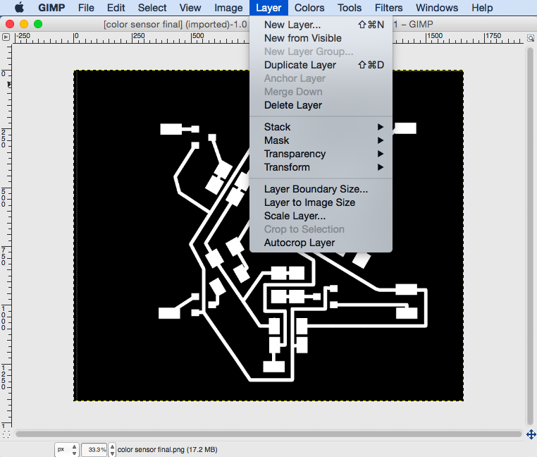
1) If your design is paired with a layer that was created in Eagle then load the monochrome image of the Eagle PCB tracks into GIMP and create a white layer above it.
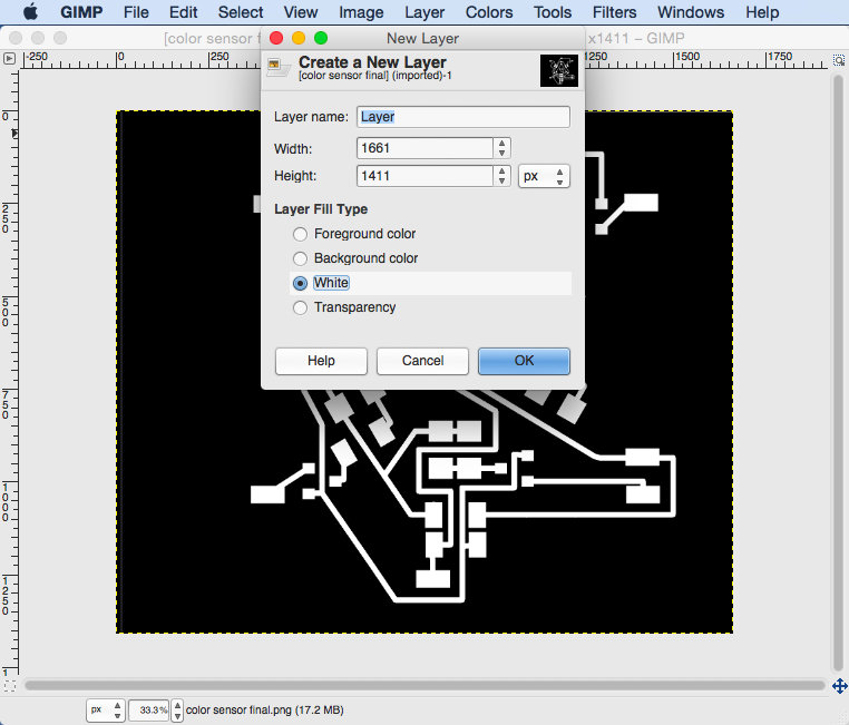
2) In order to make sure that the pads align for the vias through the board you will need to decrease the layer transparency to about 50%.
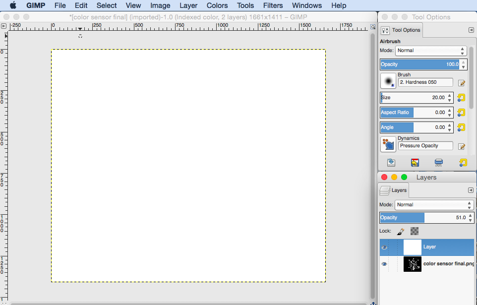
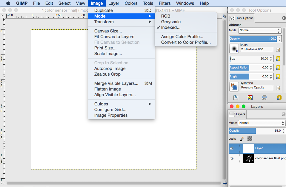
3) You will notice that there is no change in the transparency until you reach 50% at which point the layer goes completely transparent. The reason for this is that the Image mode settings are set to Indexed instead of Greyscale or RGB. Change these settings by going to Image -> Mode -> Greyscale
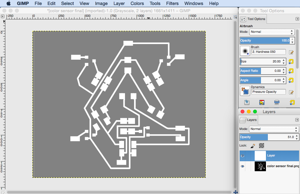
4) Now you will need to make you white layer completely black as your traces are going to be white by convention. So use the paint bucket tool to paint it black.
5) In order to draw the pads you can use the rectangle select tool and trace over the corresponding pads on the bottom GIMP layer – the size of the pads do not have to be exact as long as they are the same or larger than those below.
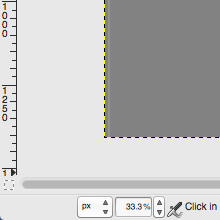
6) In order to draw the traces you will need to be a bit more careful: I found it helpful to change the units in GIMP from pixels to millimeters as I knew that the traces in Eagle were about 0.5mm wide. This units can be change at the bottom left hand corner of the window. Now when you use the rectangle tool to create selections to be filled in white you can make sure the width of the traces are 0.5mm – this is also indicated at the bottom of the window when using the rectangle select tool.
7) NOTE: When you have finished the traces you will need to horizontally flip the layer you created before exporting to png.
8) Make sure that you increase opacity back to 100% before exporting to png.
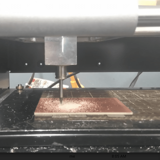
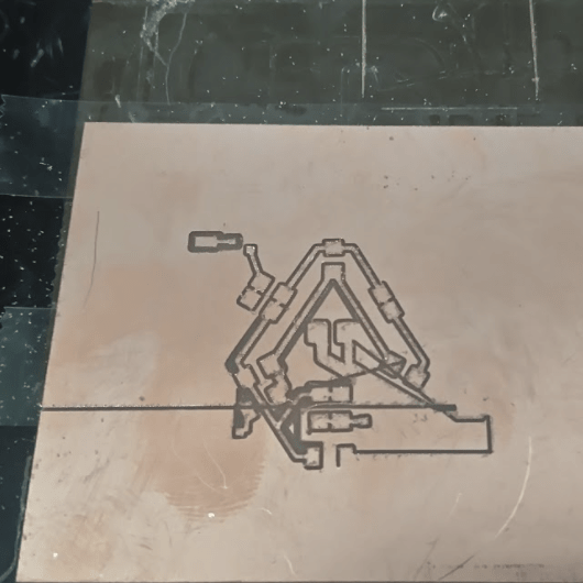
I began by milling on the Roland Mill, but after much frustration and confusion I gave up. Shown below is the traces that were calculated by the mill as well as two failed boards. The mill went sort of crazy at 27% and would draw lines through the board.
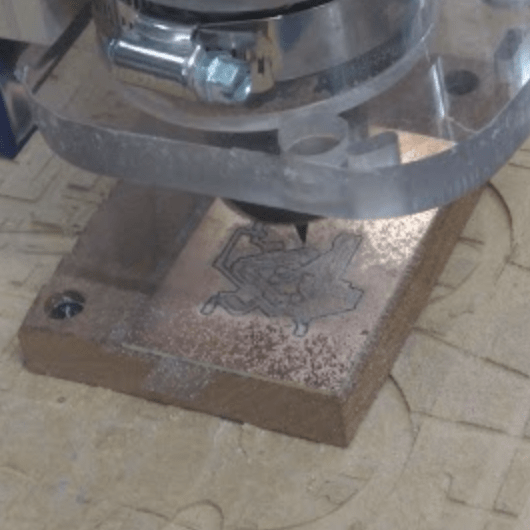
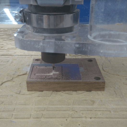
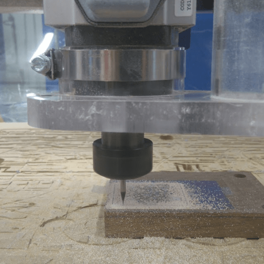
ShopBot time!
I loaded a new board into the shopbot and began the process again. This time it worked out.
Tips for milling a double sided board:
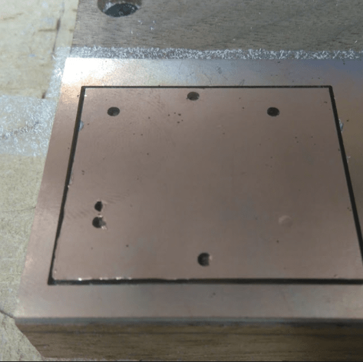
1) Mill the top layer traces then mill the vias and outline. After this only remove your board from the stage, flip it over (make sure that you alignment is correct) and place it back into the hole. This allows you to align it so that you do not have to re- zero x and y.

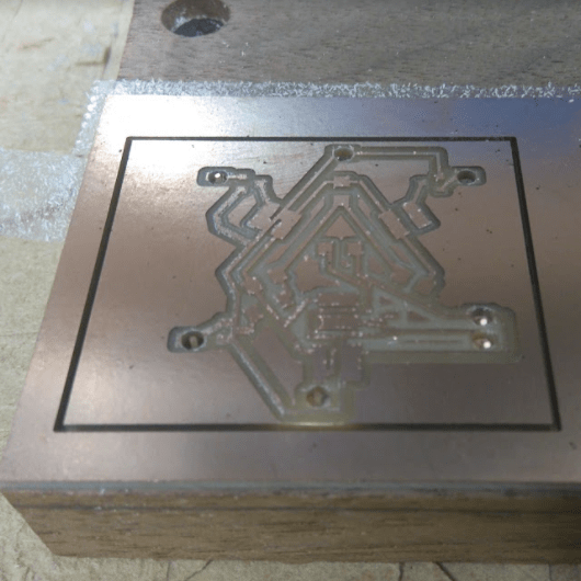
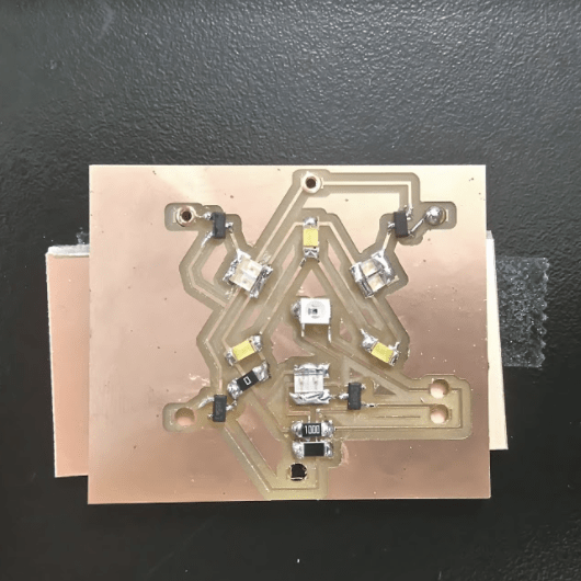
The board came out very well except for a couple of place where the tracks were too close and it did not cut between them. I manually cut these traces with a craft knife and loads of patience.
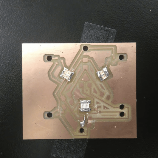
Soldering Time!!!
I began by Soldering the top side of the board – as well as placing in the vias. Oh my goodness! Make sure that you have the correct size holes for the vias – mine are way too big and the vias do not fit very well. It took me soo long to fill the board that I ran out of time. I will need to program it asap.
.