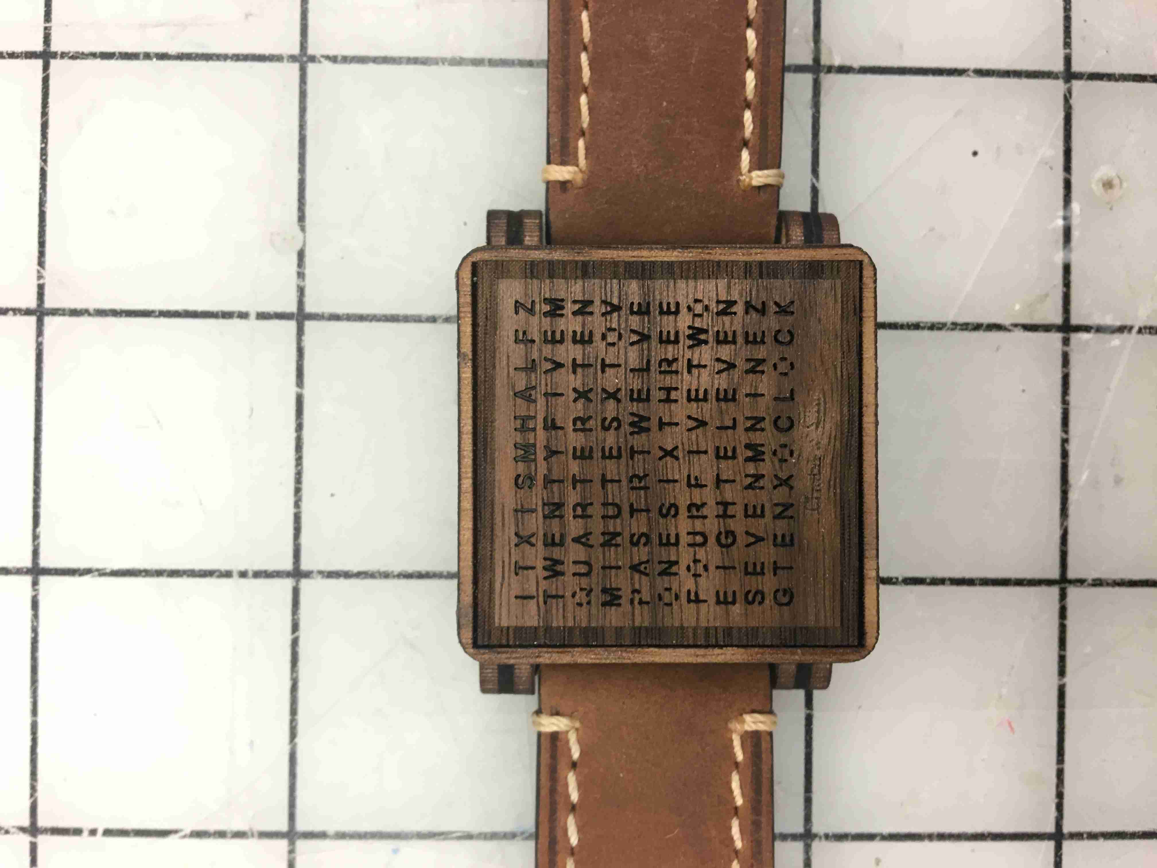
Building a word watch clock
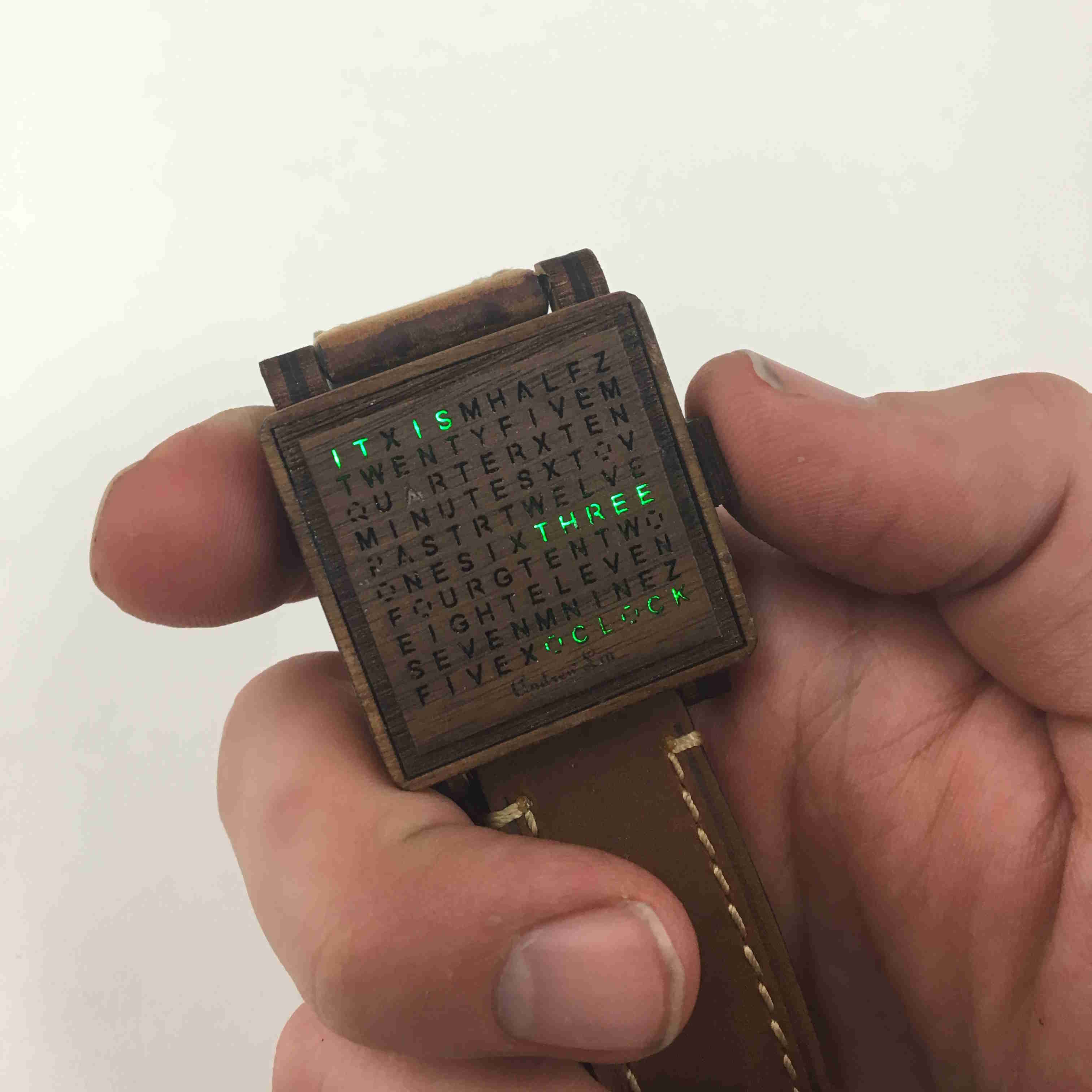
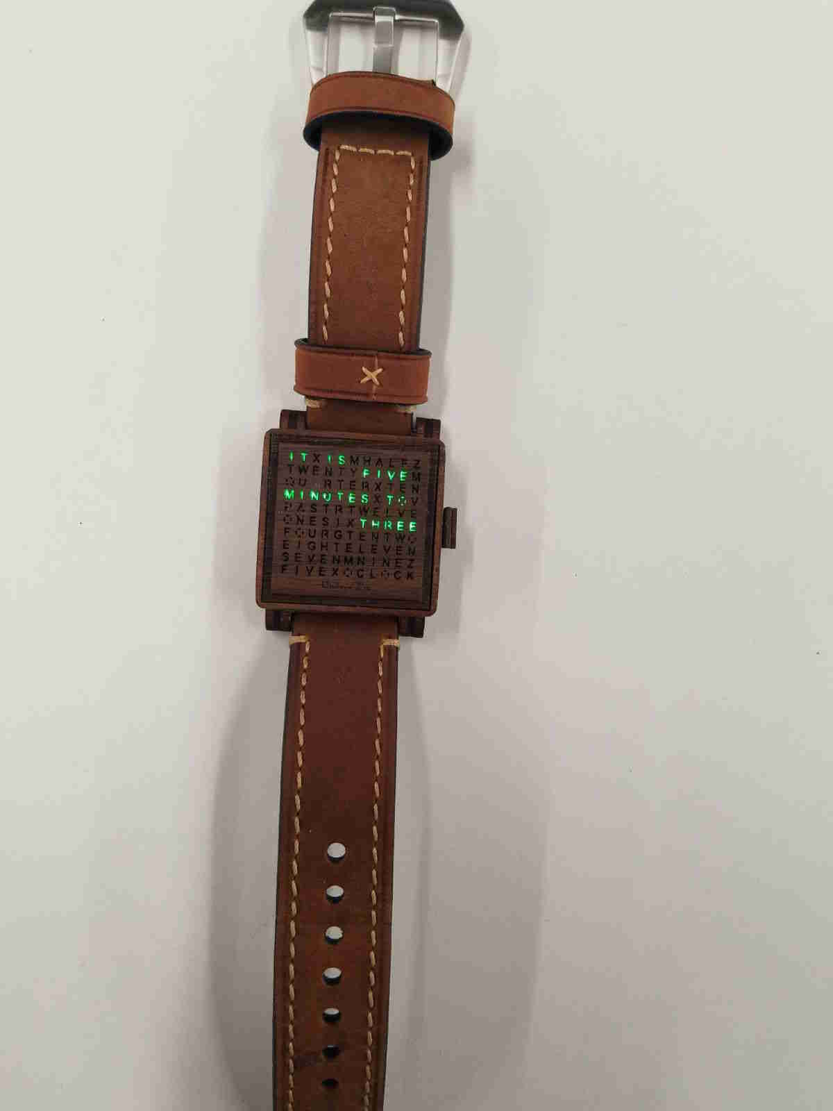
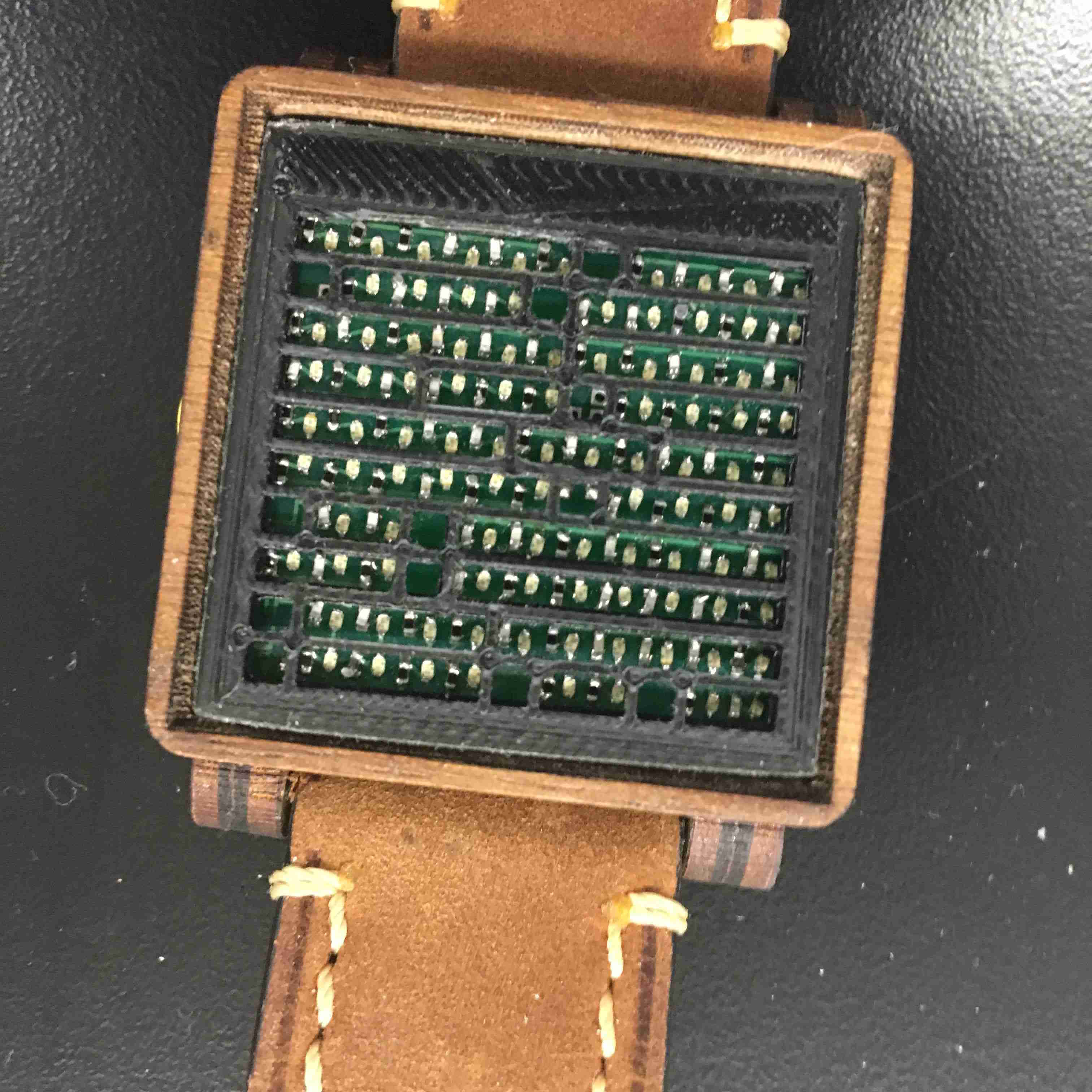
This is the final piece. When you click on the walnut button on the side, it'll tell you the time in words, to the nearest five. Thank you Mark for your beautiful hand modeling.
Here's a better version of everything.

This is me wearing it! I call dibs on Facebook profile pic.
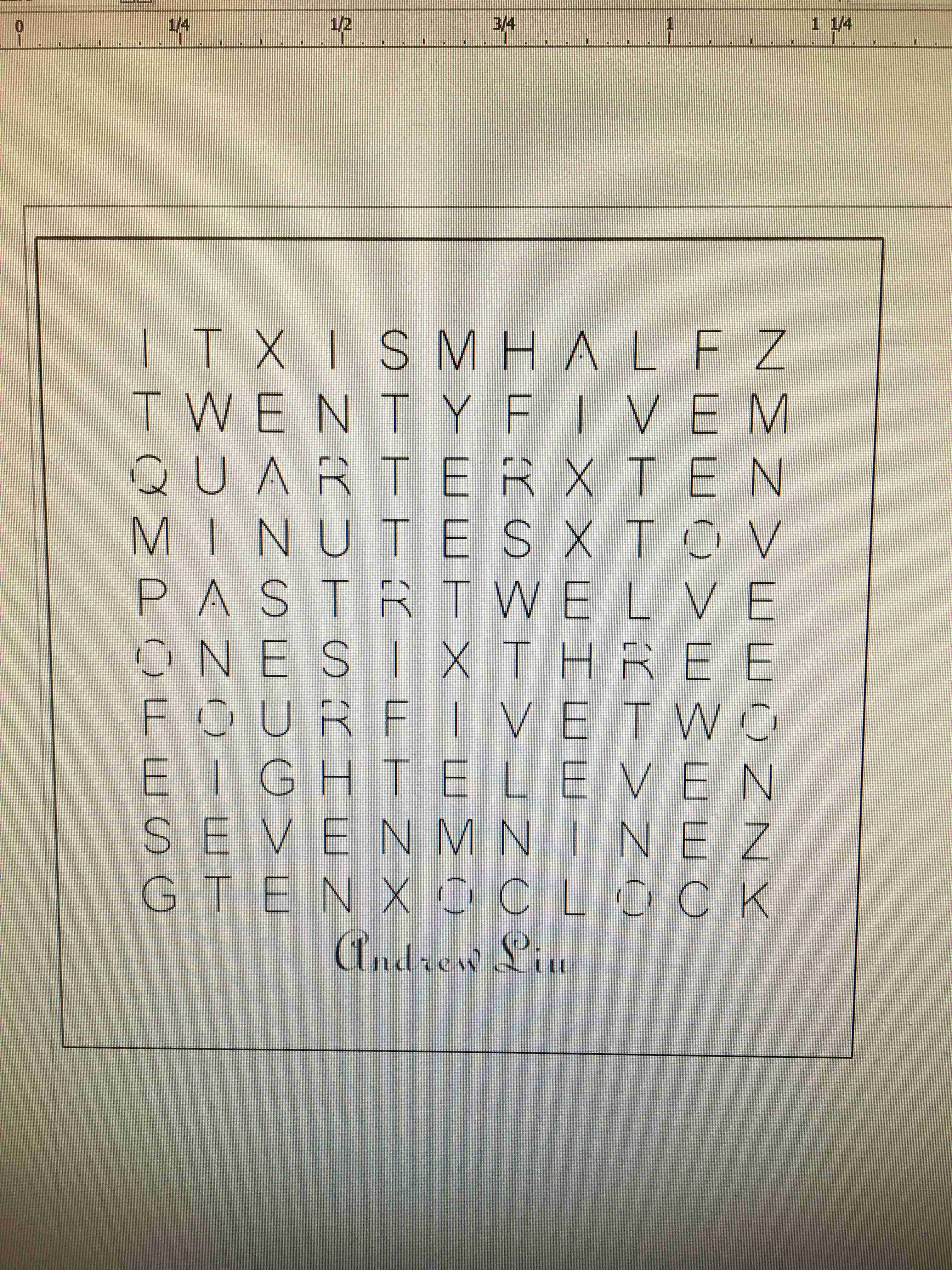
Starting with the WatchFace
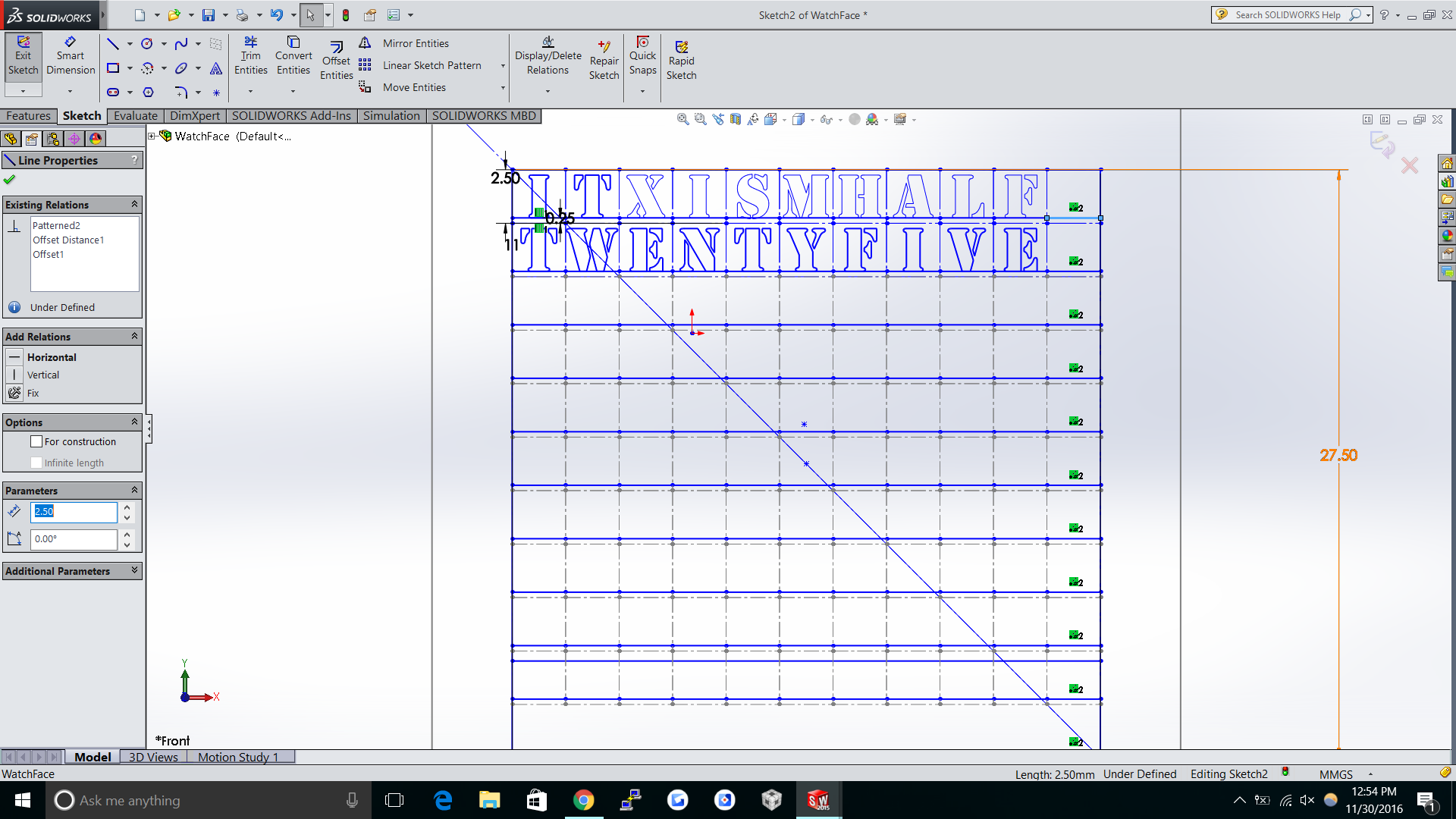
I started with a simple solidworks file. The worst part was getting everything
centered and then having to go one item at a time for text since you can't linearly move text.
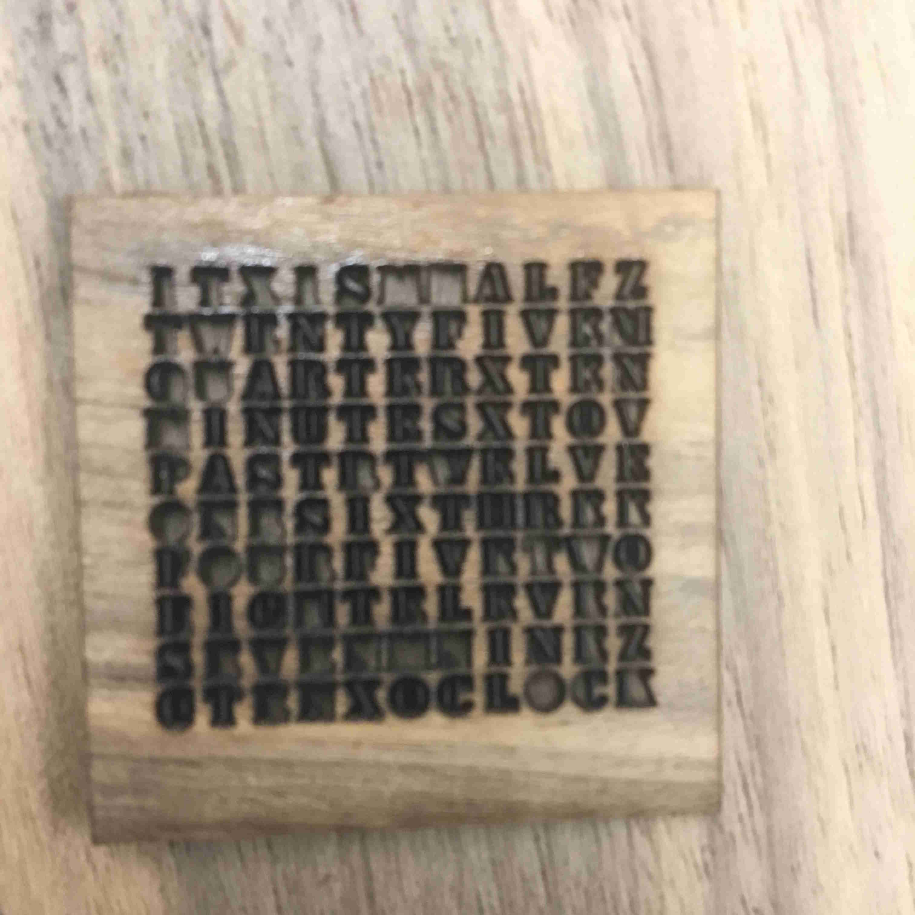
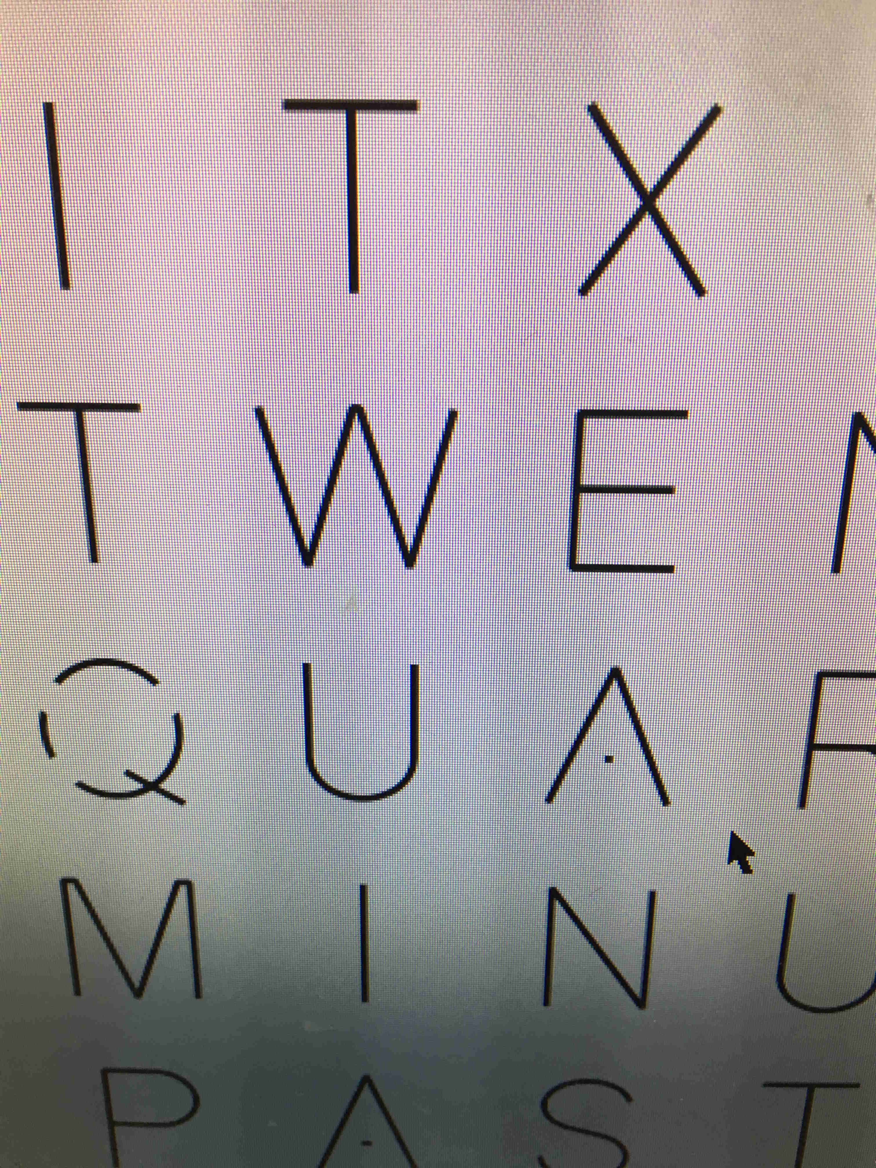
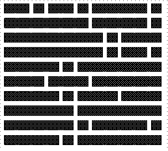
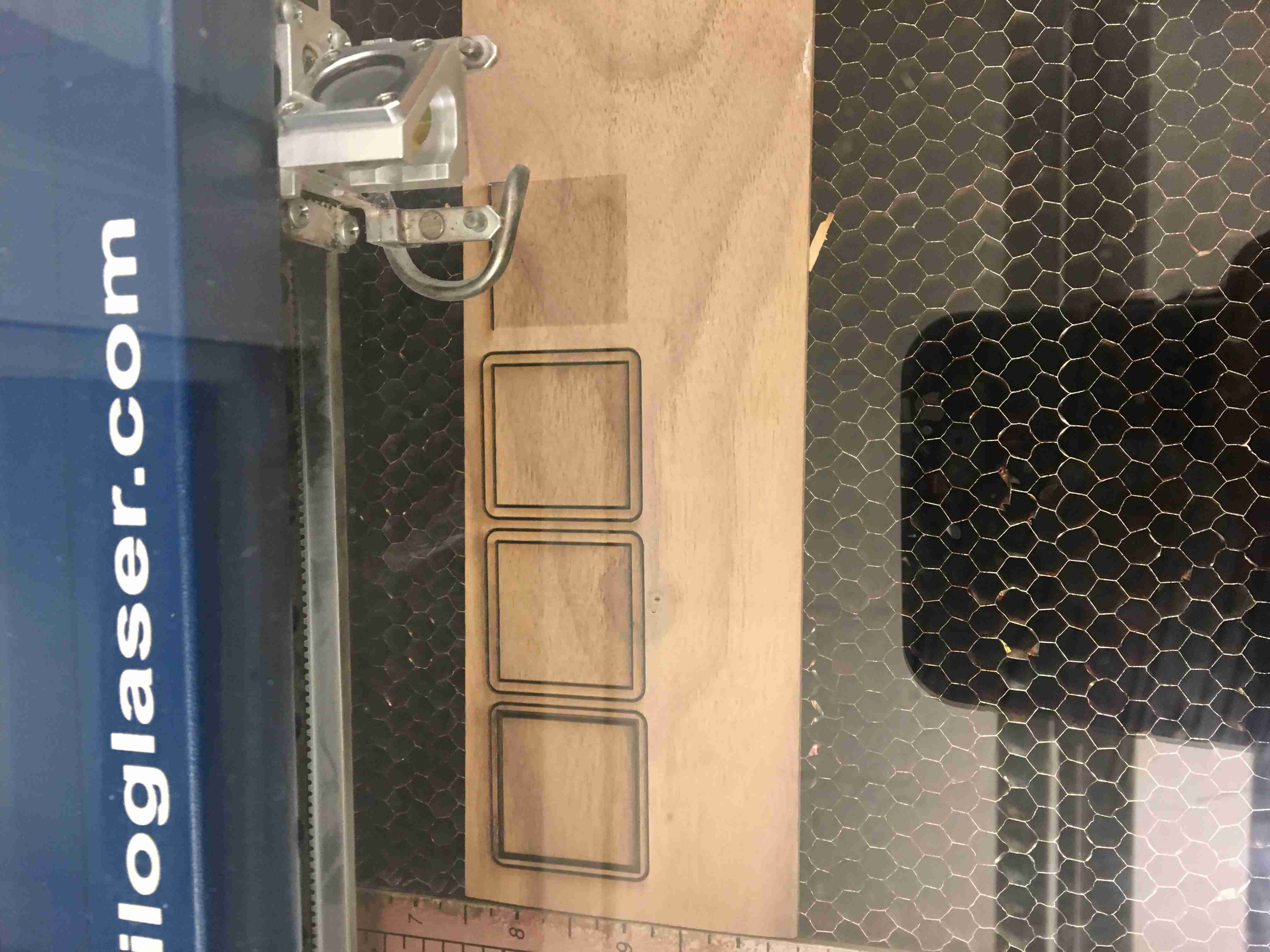
I started by doing a "raster cut". Basically, I just rastered the same thing over
and over again on the wood. Because the face is so small, one laser cut of .005" inches is
actually a lot of cutting off. Just using a normal stencil font outline would cut open the entire piece.
Rastering seemed like a better idea.
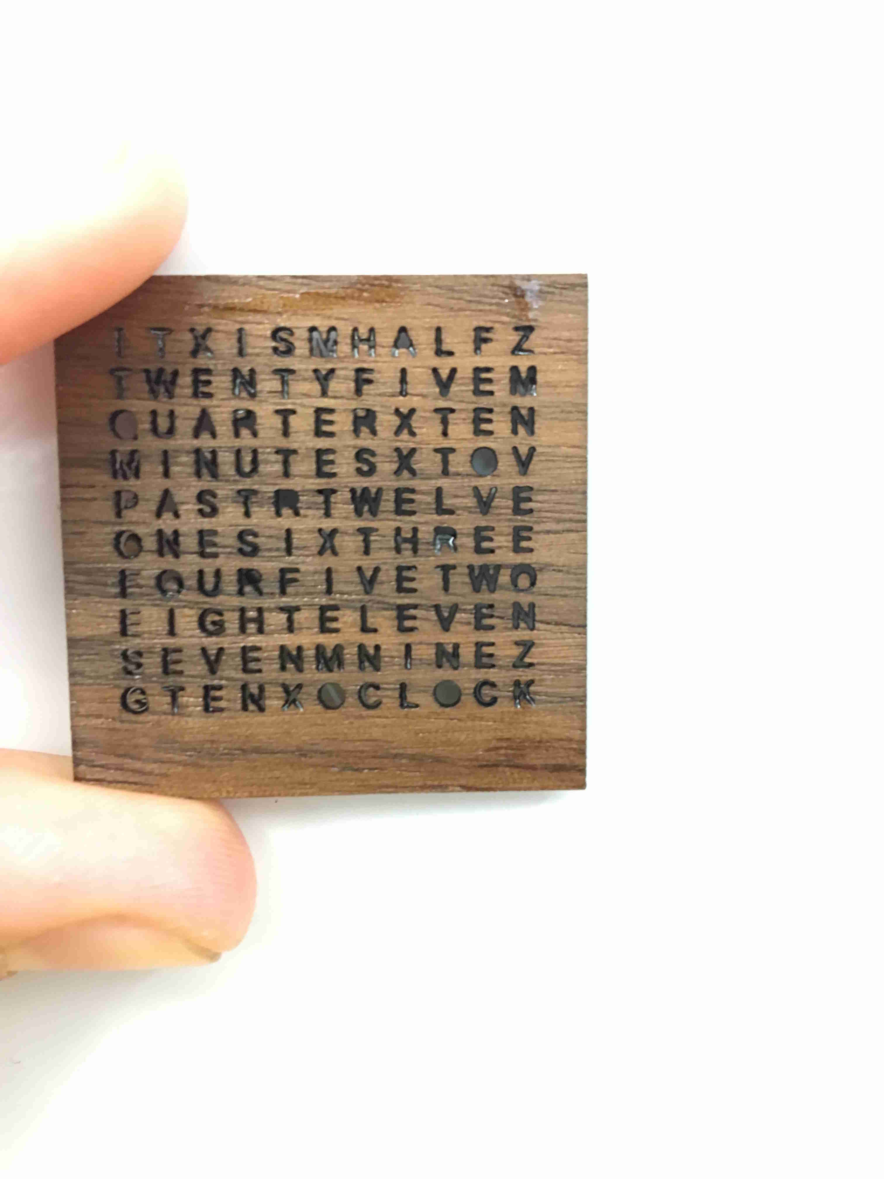
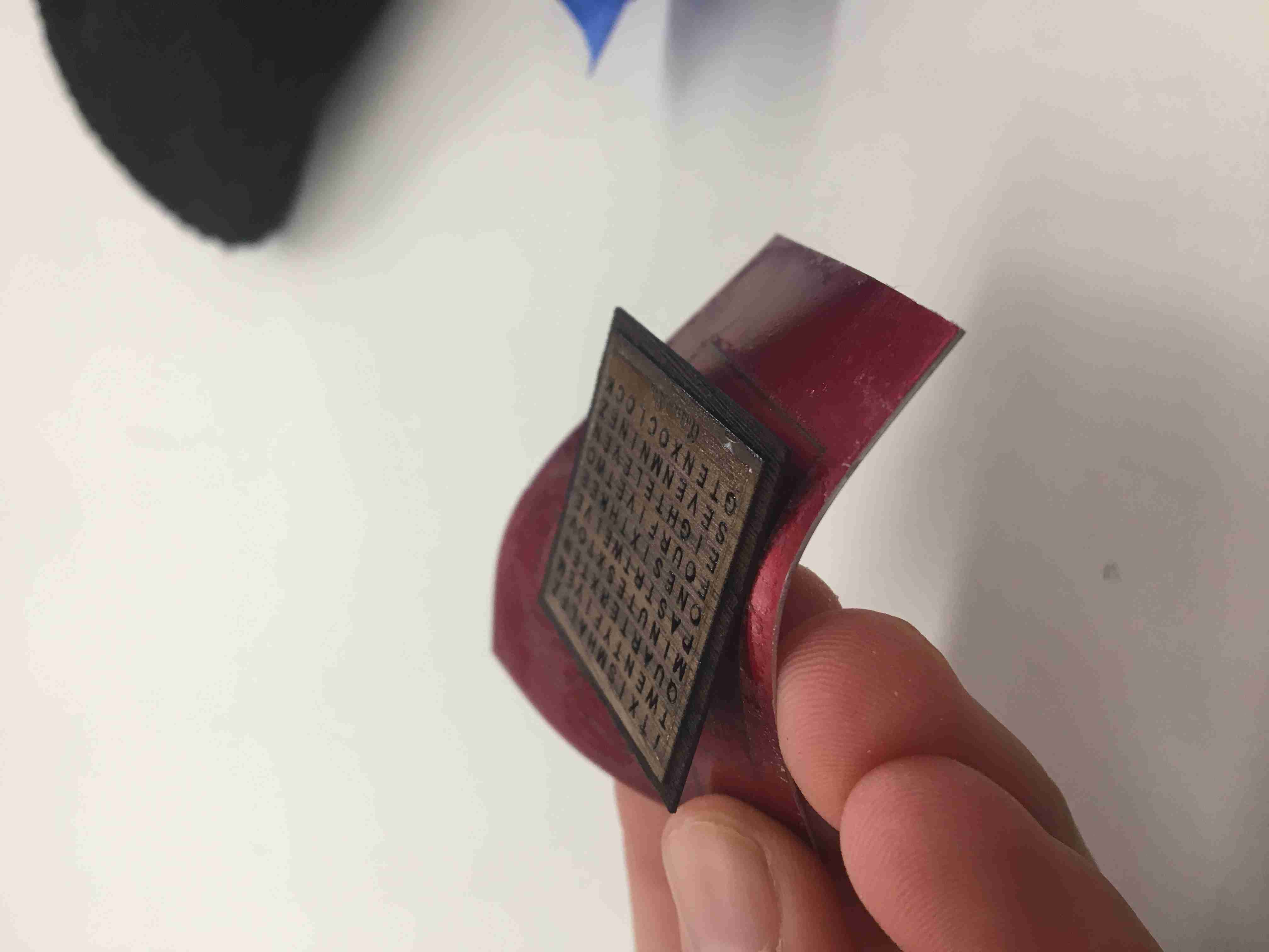
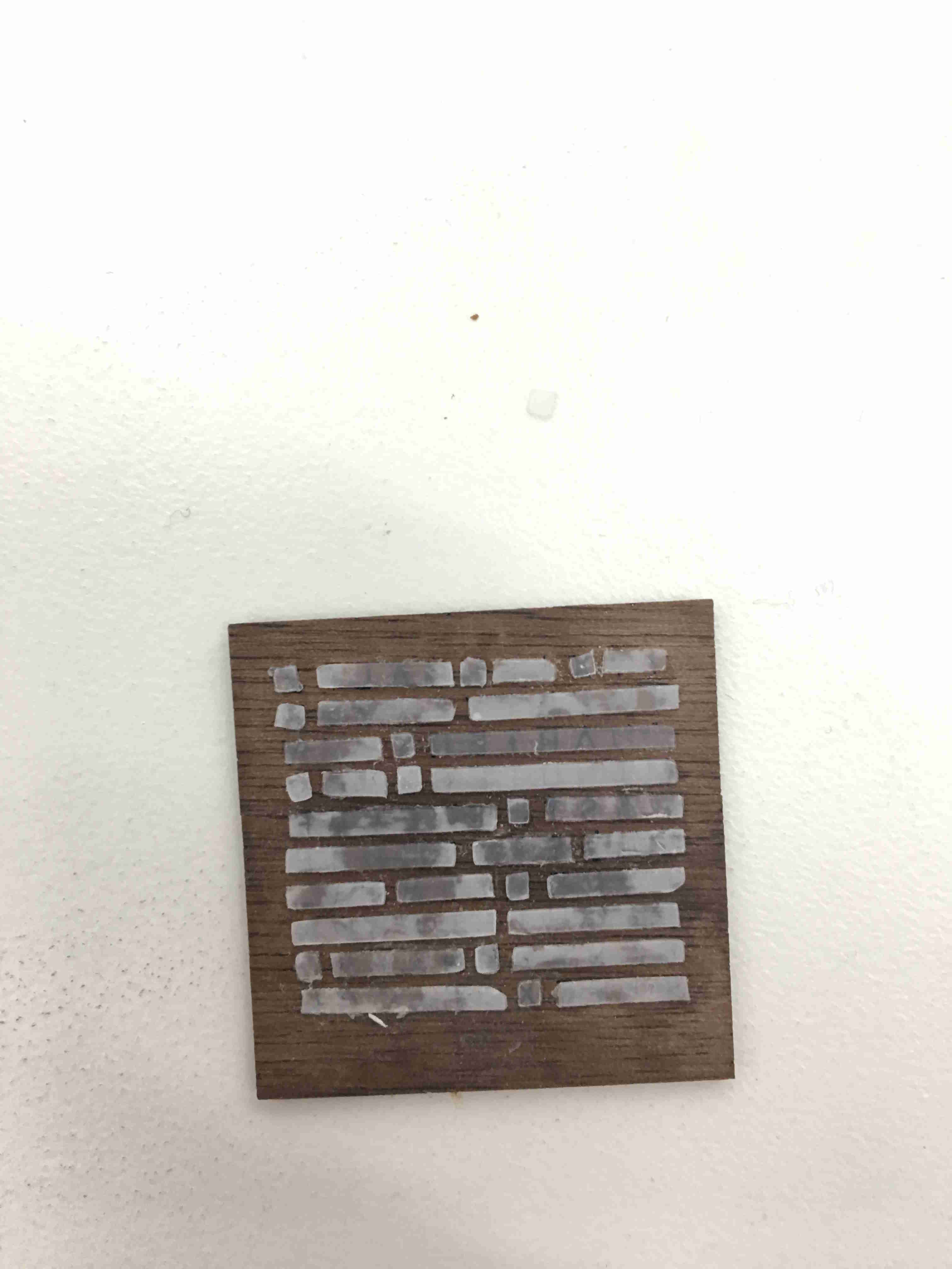
I ended up using a "One Vector" only font that Solidworks had, but it created these little holes you can see.
A lot of the next couple hours was trying to eliminate the holes by using polyurethane
to chemically stabilize the inner pieces of the "O" and the "P"
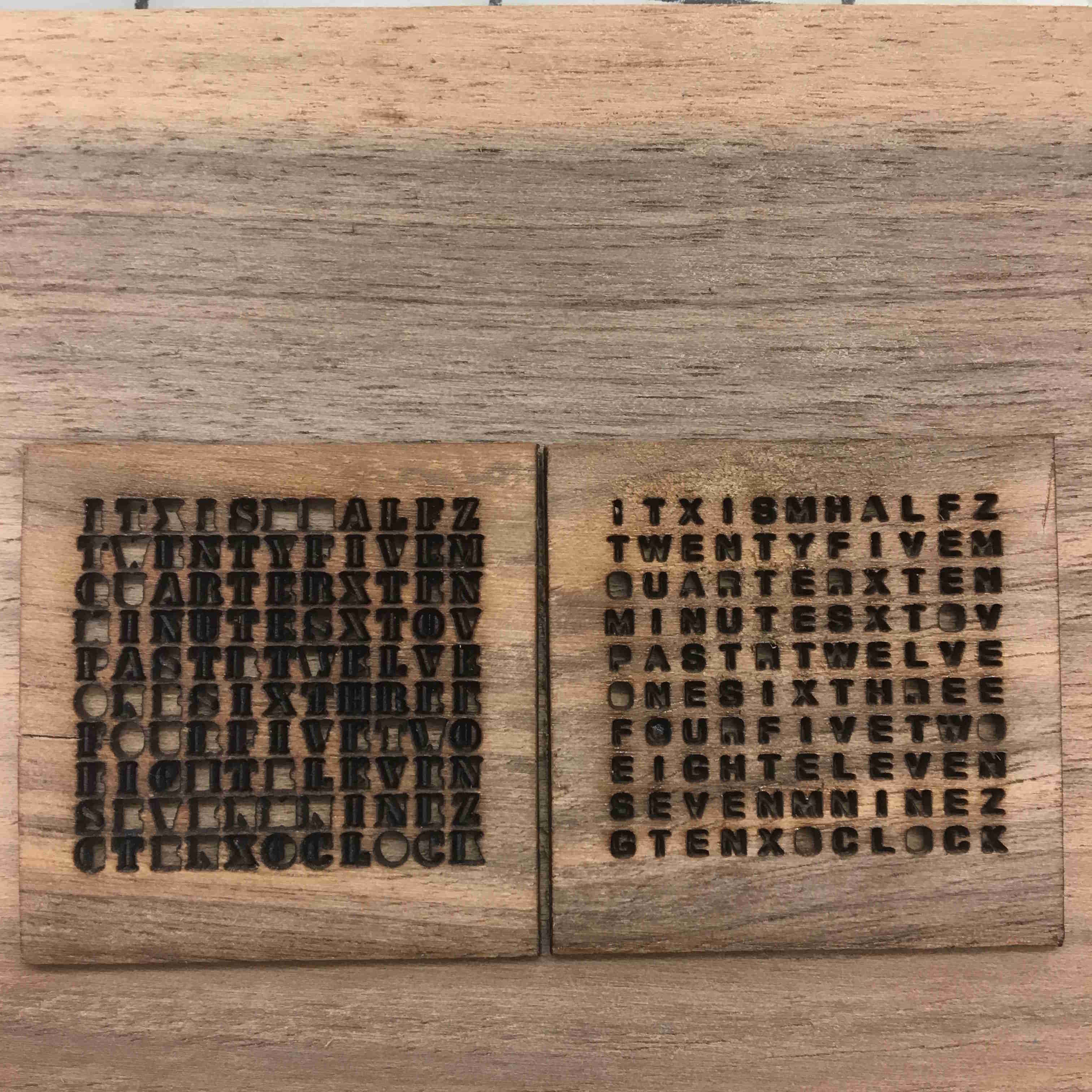
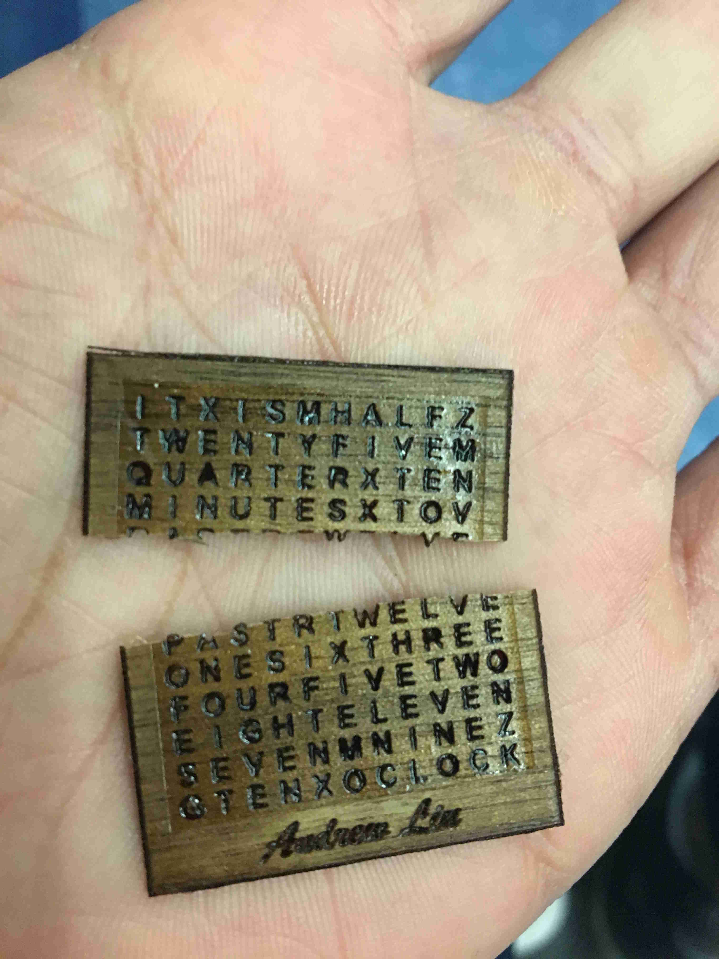
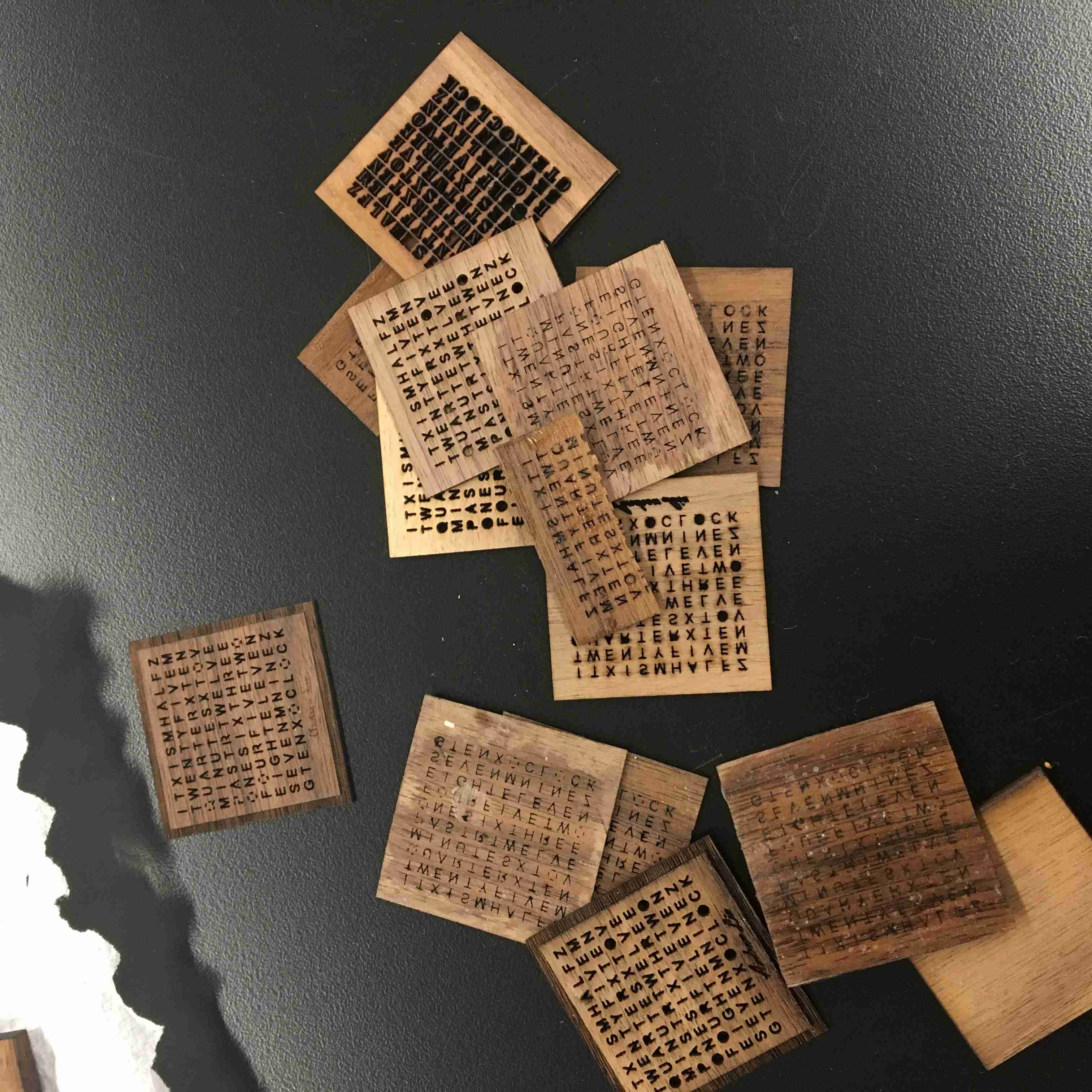
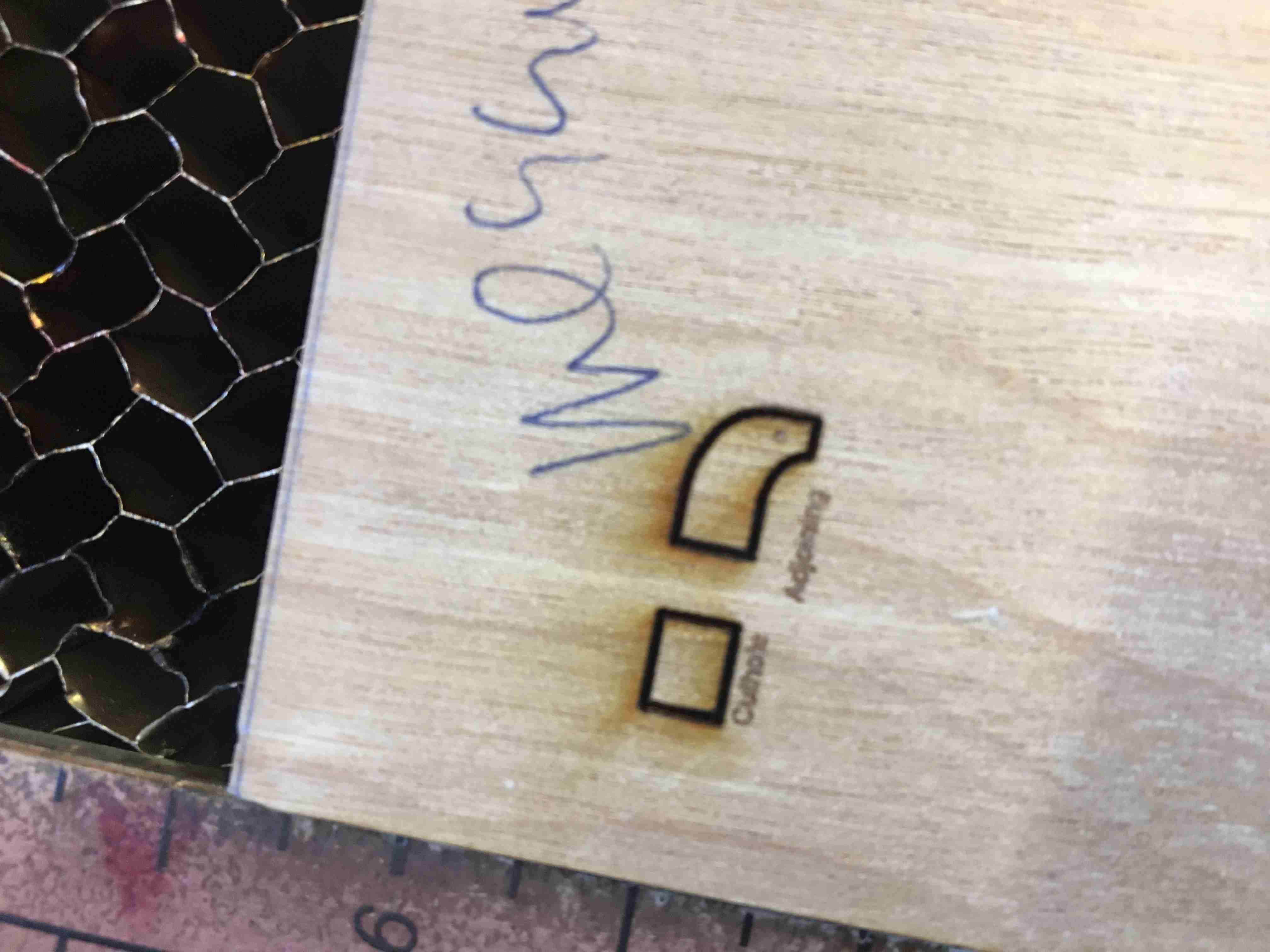
Here are them both side by side. The Raster is on the left and the vector is on the right.
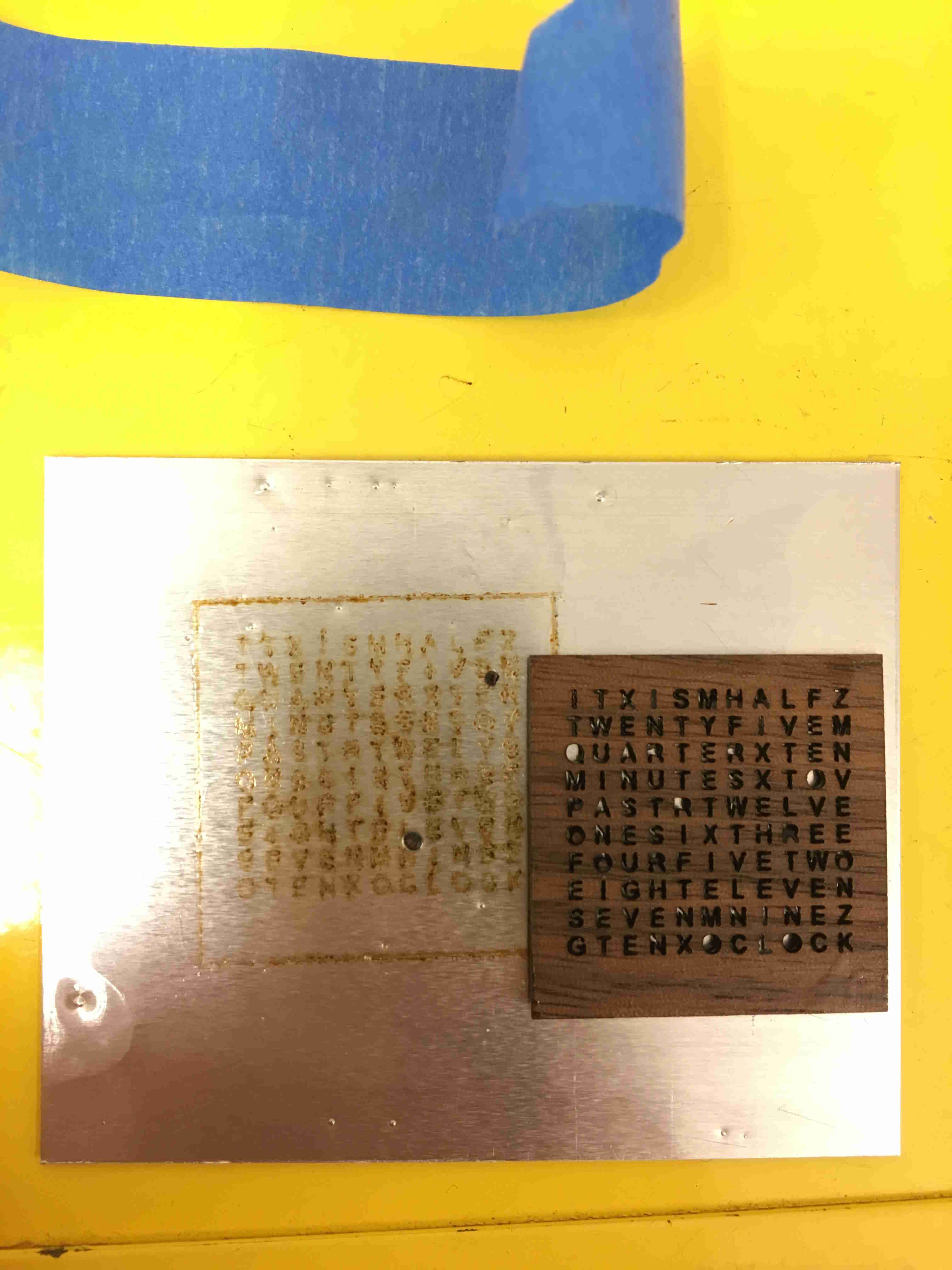
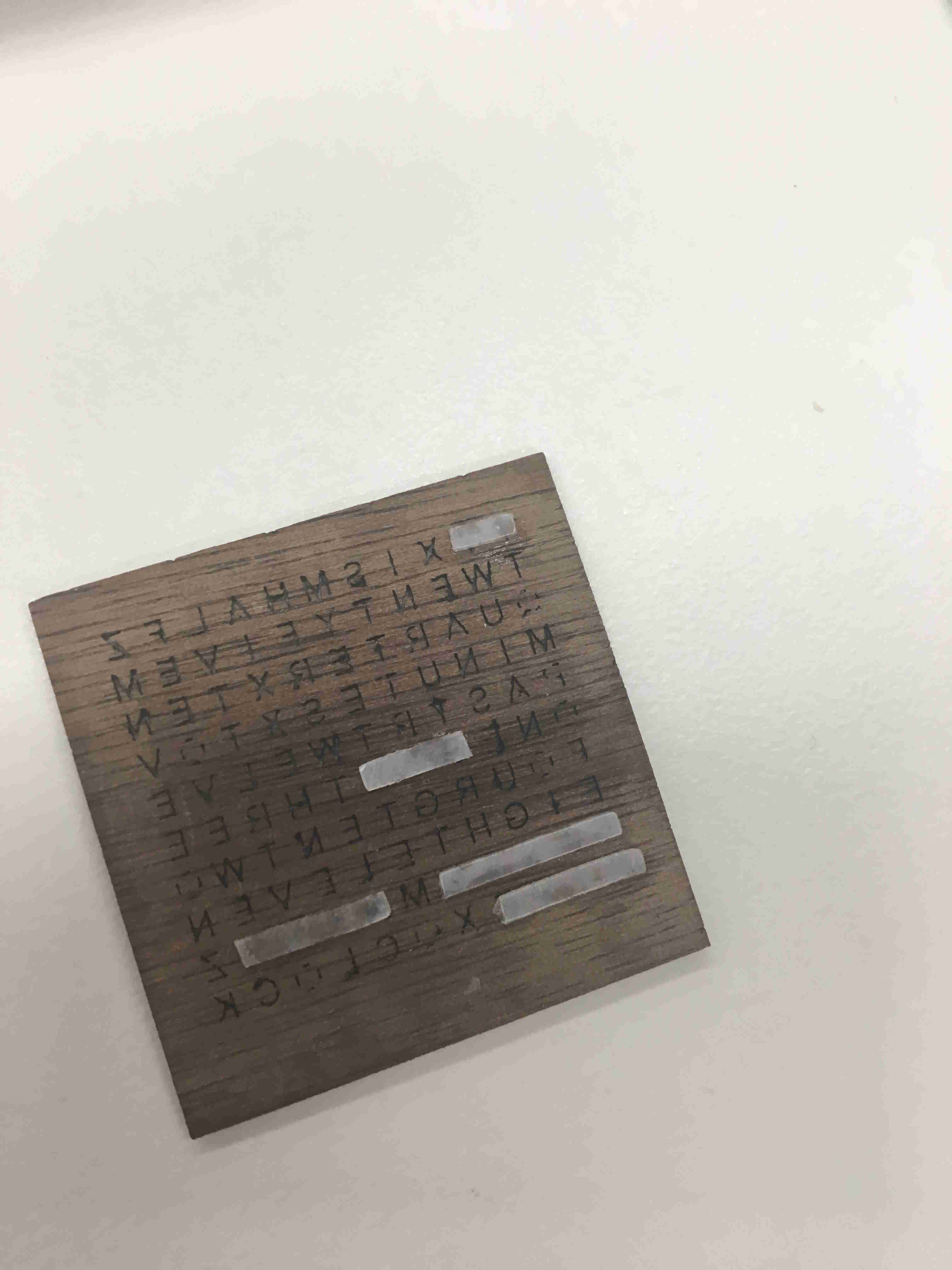
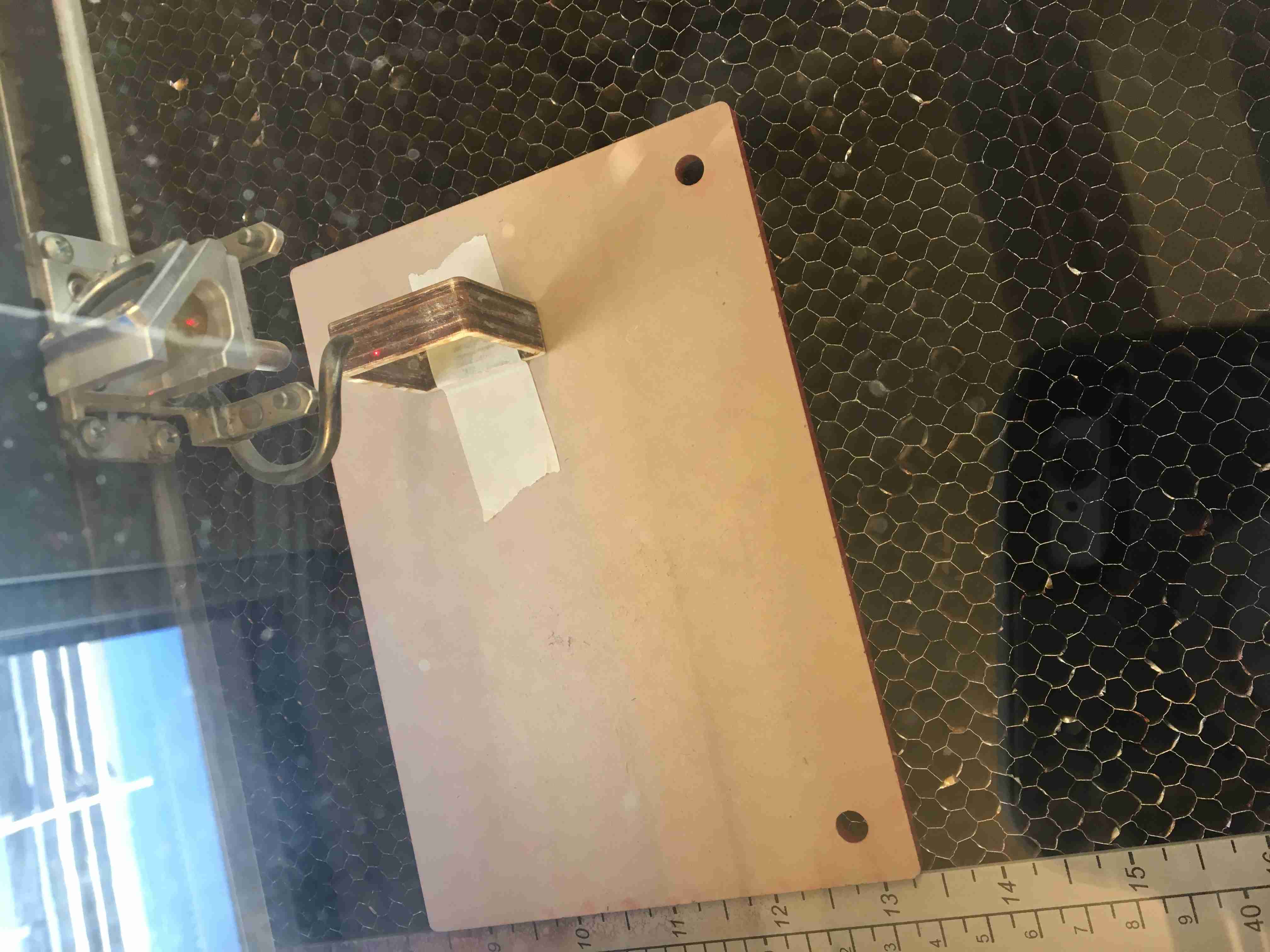
A CO2 Laser can cut through wood but can't cut through metal. Hence, I had a
piece of metal on the back of the wood to catch the inner pieces of the "O" and the "P". I held it all together with the blue scotch tape.
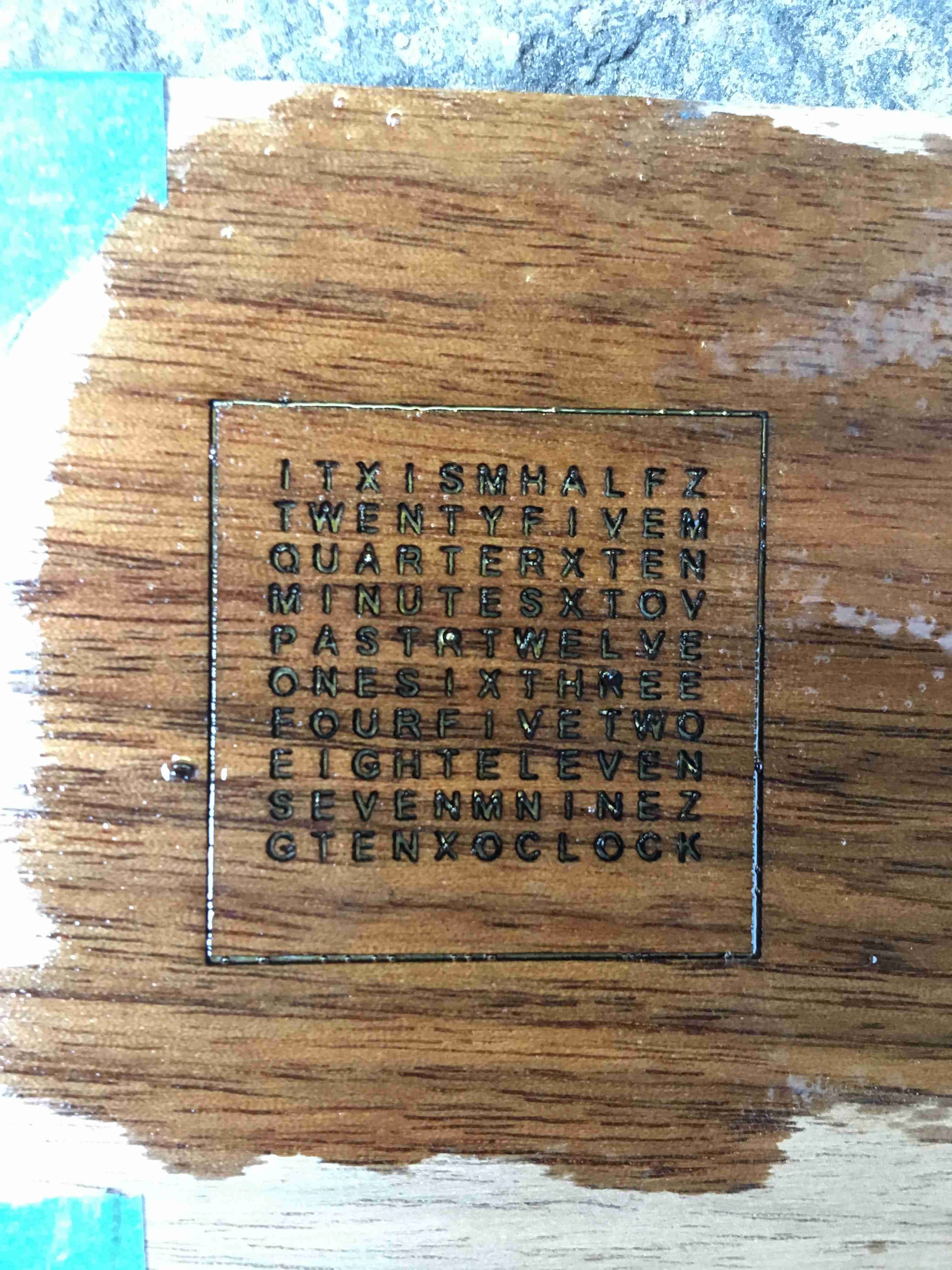
After it was held, I covered the piece with polyurethane and let it dry. There were around two iterations with this.
- Polyurethane with metal backing. This failed because the polyurethane just seeped under the metal.
- Polyurethane with metal backing and tape on top of the wood to hold it down. This worked, but it took a lot of wood.
The best thing about metal is how you can bend it. Although the polyurethane
glued to the metal, because I could bend the metal out and safely remove
the wood, which was EXTREMELY fragile.
Emphasis on extremely fragile.
Not bad. But I was honestly unsatisfied. Andrew isn't going to wear something
that looks messy, and the pieces in the center look messy. They're all lopsided.
Back to the drawing board.
I ended up making my own font. It was a combination of stencil and the solidworks vector file.
It took a lot of back and forth. There was one time when everything looked right,
but the R just looked a LITTLE weird, and I redid the entire thing again. I can't have
Andrew wear something with stupid 'R's!
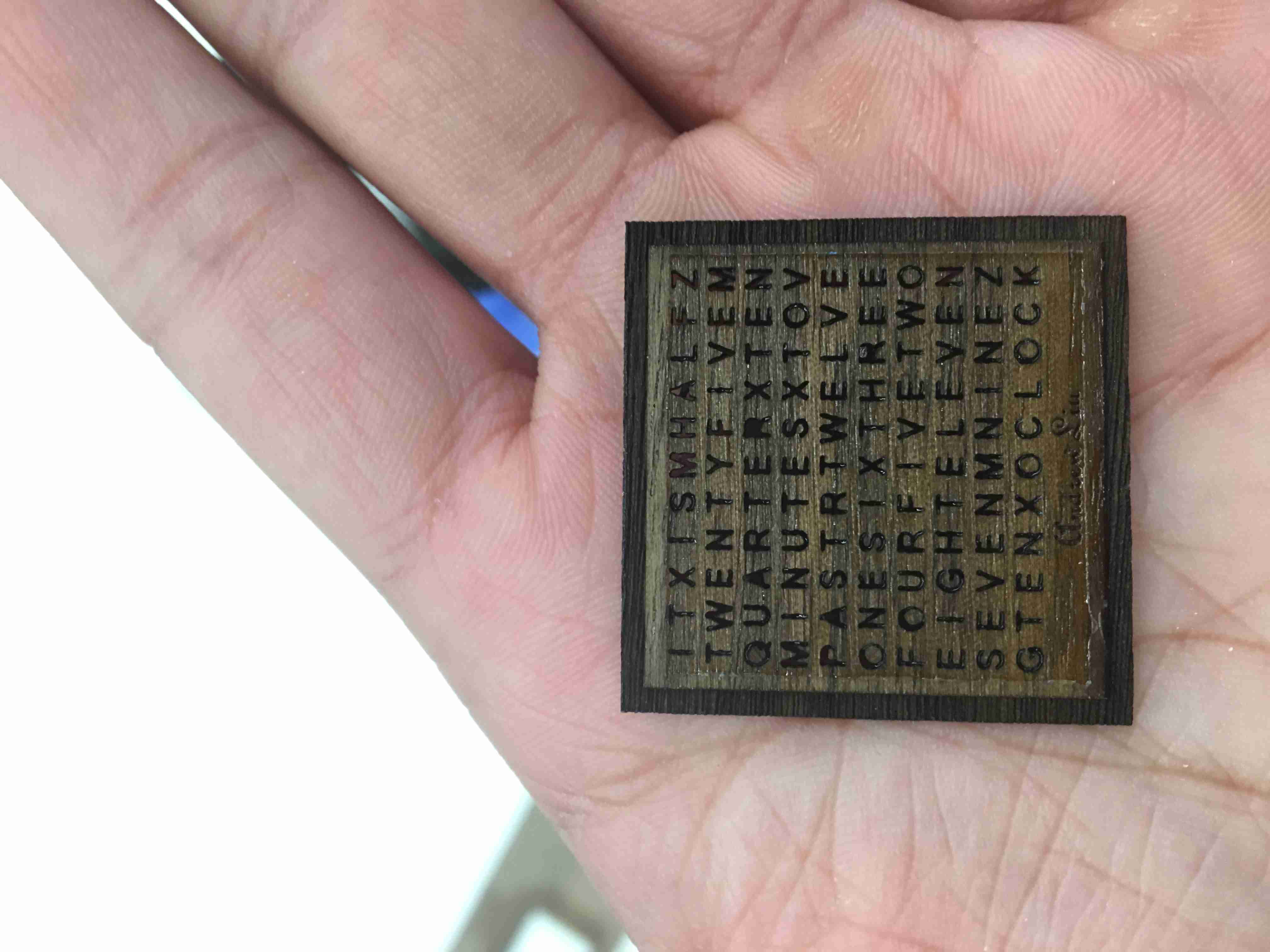
All done. Everything has stencil fonts and just enough space to hold it.
Boom. Looks nice.
Once this was done, I needed diffusers for the light. I originally didn't care
about diffusers, as the LEDs I bought alrady diffused, but after some tests, they didn't look good.
I wanted to illuminate the light at the top of the wood, but as you'll see later (I continued to iterate with this problem
throughout my entire design process), it was difficult. In the future, I'll figure it out.
To get the diffusers, I created a VinylCut outline of the baffles I made. The vinylcut fab module cuts out the black and keeps the white.
I didn't have an actual vinyl for tranparent, so I used Rahul's transparent plastic and used super glue to hold it
to the back of the case.
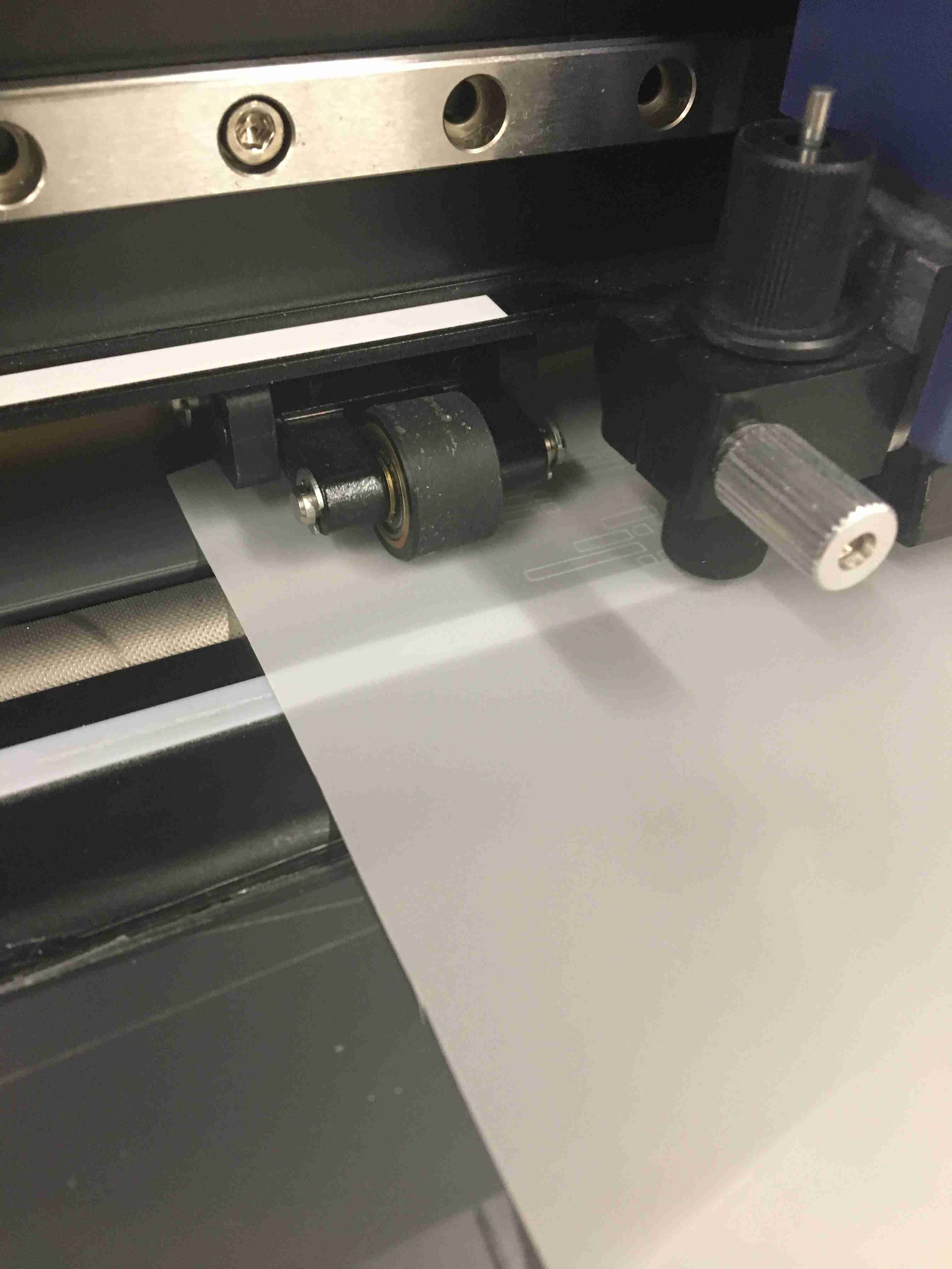
Go vinyl cutter go!
The final backing.
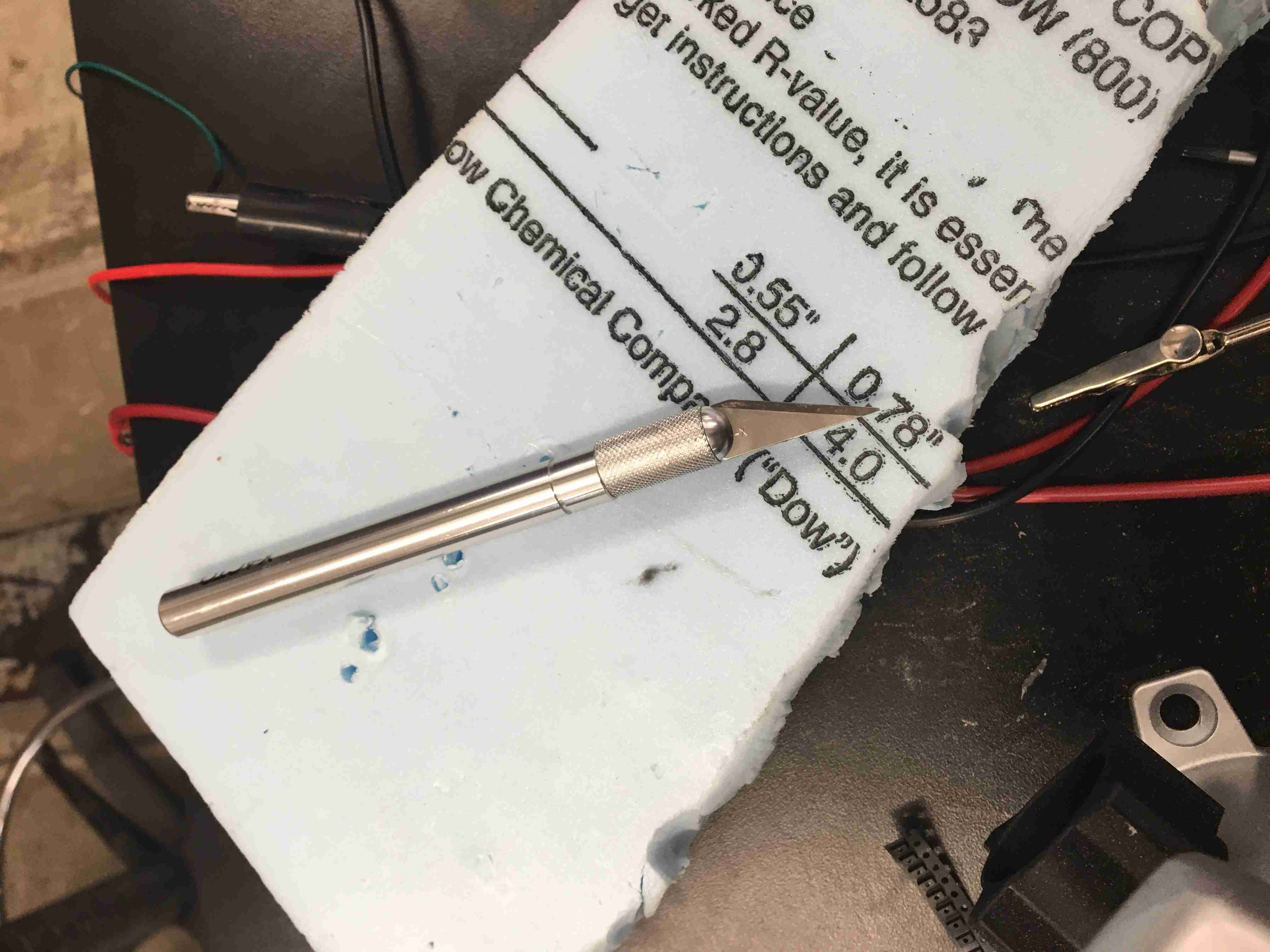
Next up are the baffles. You need to stop an LED from illuminating letters they shouldn't.
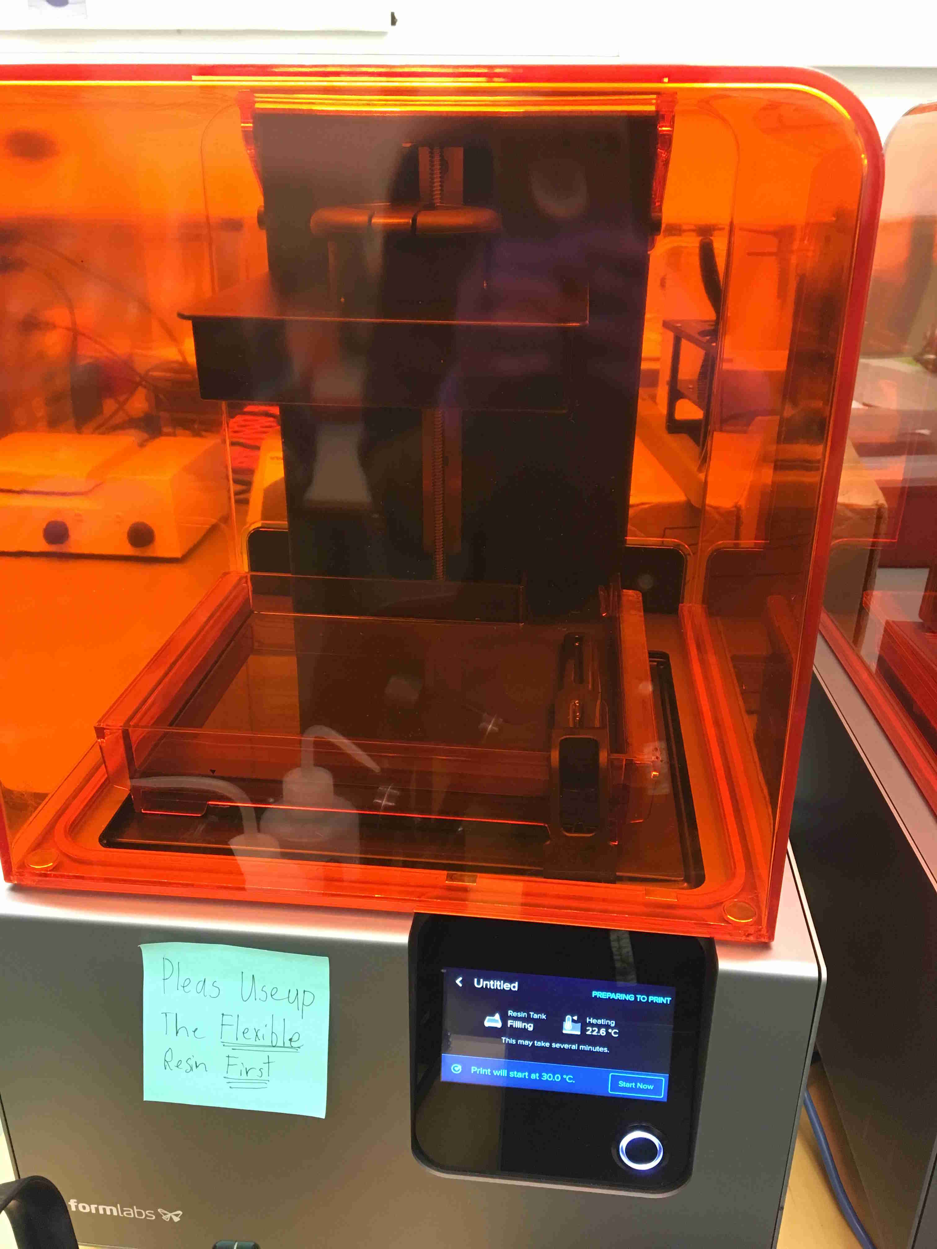
I used the Formlabs printer because I thought it would be more helpful. It has "flexible" 3D prints.
For all 3D printers, you need a .4mm minimum wall, which meant I had to change my entire design so that it was a .4mm wall.
I ended up not using it because the flexible prints had slight overlays on the walls.

FormLabs requires the following steps:
- First, you print.
- Scrape off the piece from the top of the 3D printer.
- Catch it and place it in an alcohol bath.
- Cure it with a dose of UV light (i didn't end up doing this)
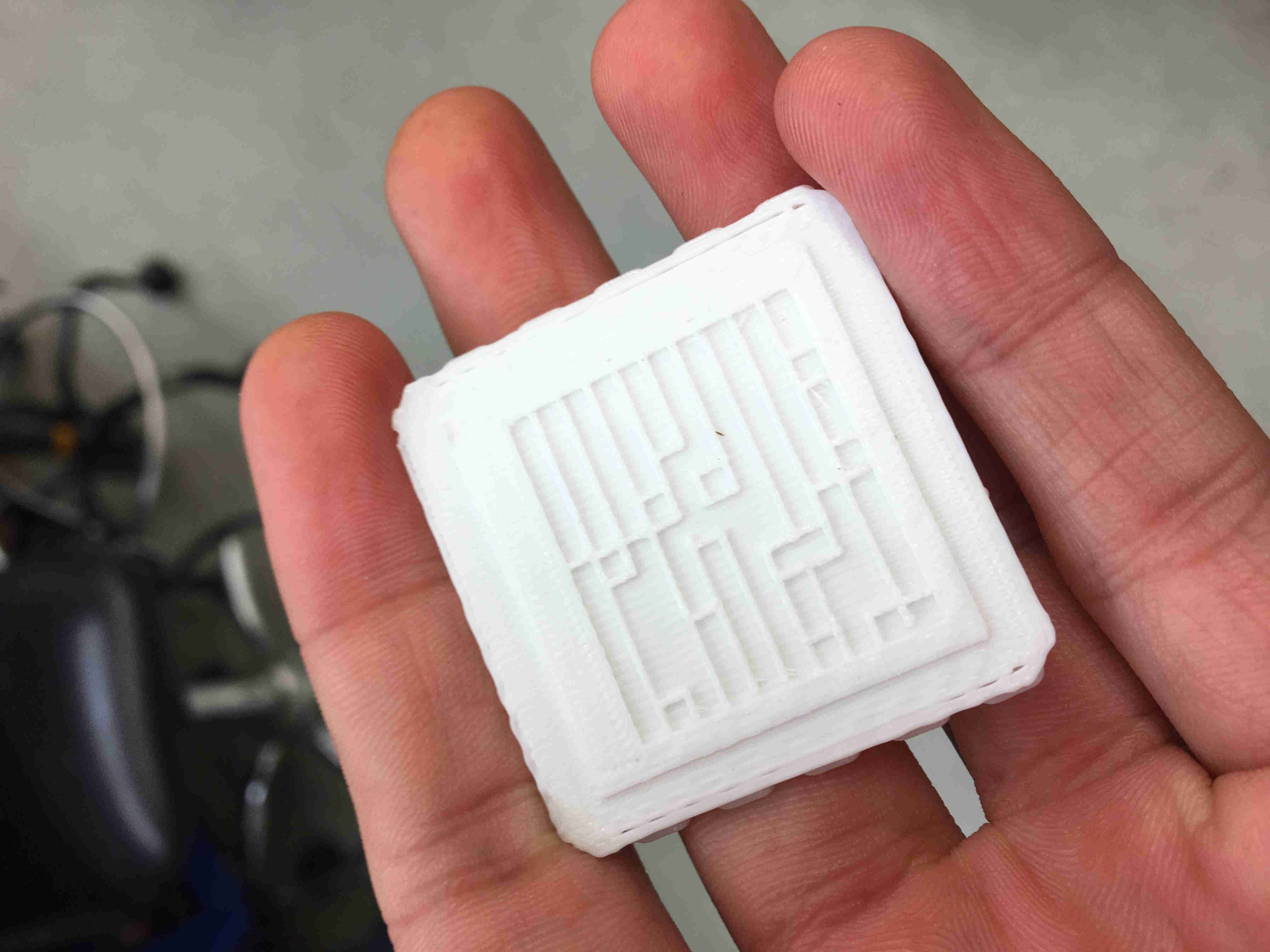
The second iteration! I forgot to turn off the raft on the button. Ugh.
I screwed up the circuitry in that my tolerances were off. Due to not having
parametric modeling on EAGLE, I had to manually move every LED, which was very time consuming.
Not fun =/.
It in its final spot.
All the failures. This was a great picture to look at for motivation.
Let's get the Case.
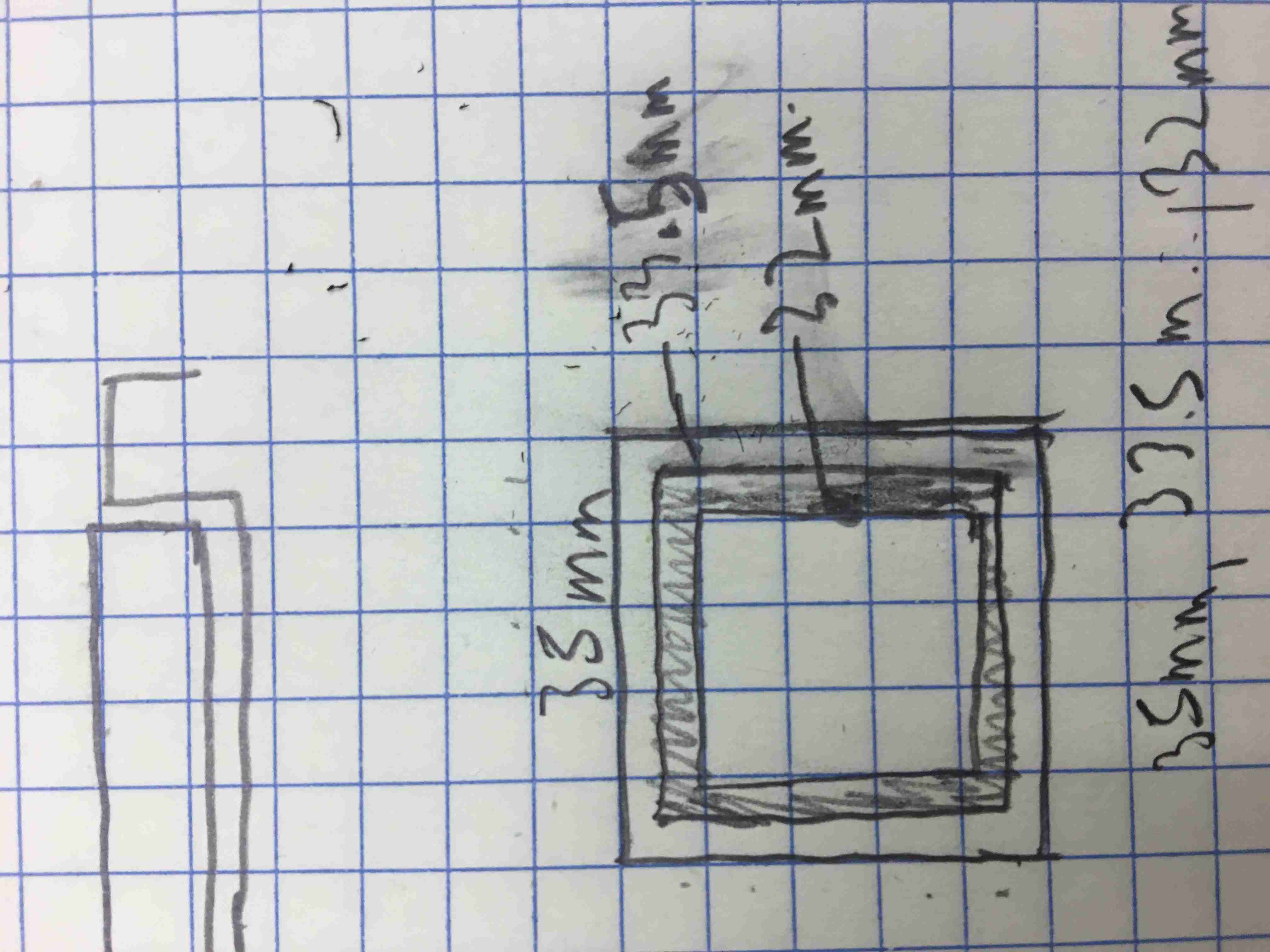
I started just by doing sketches. This was overdone so much that these dimensions don't even work.
Funny thing is, the case started out being too skinny, so I had to change the outer dimensions
to 36mm, which decreased to a solid 36mm after sanding the burned edges.
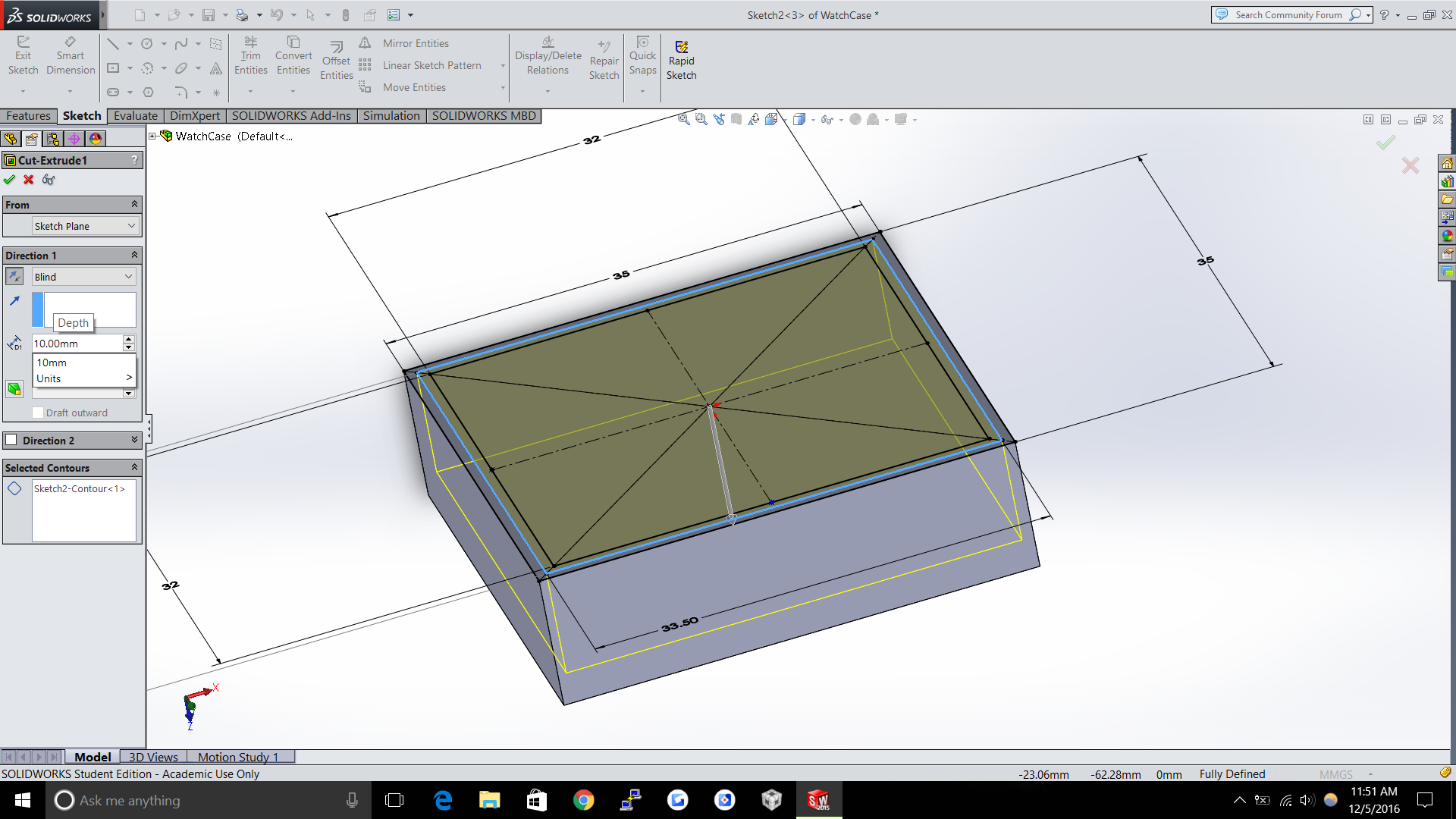
Next up was modeling it on solidworks.
I then cut out all the panels. The basic idea was to laser cut four pieces and then
stack them one after the other.
The side buttons and legs was done through laser cutting.
The side buttons and legs was done through laser cutting.
The legs needed to be laser cut and pressfit to be structurally sound. After the pressure fit, it would need
some wood glue, but the more pressure fit, the better the glue would affix.
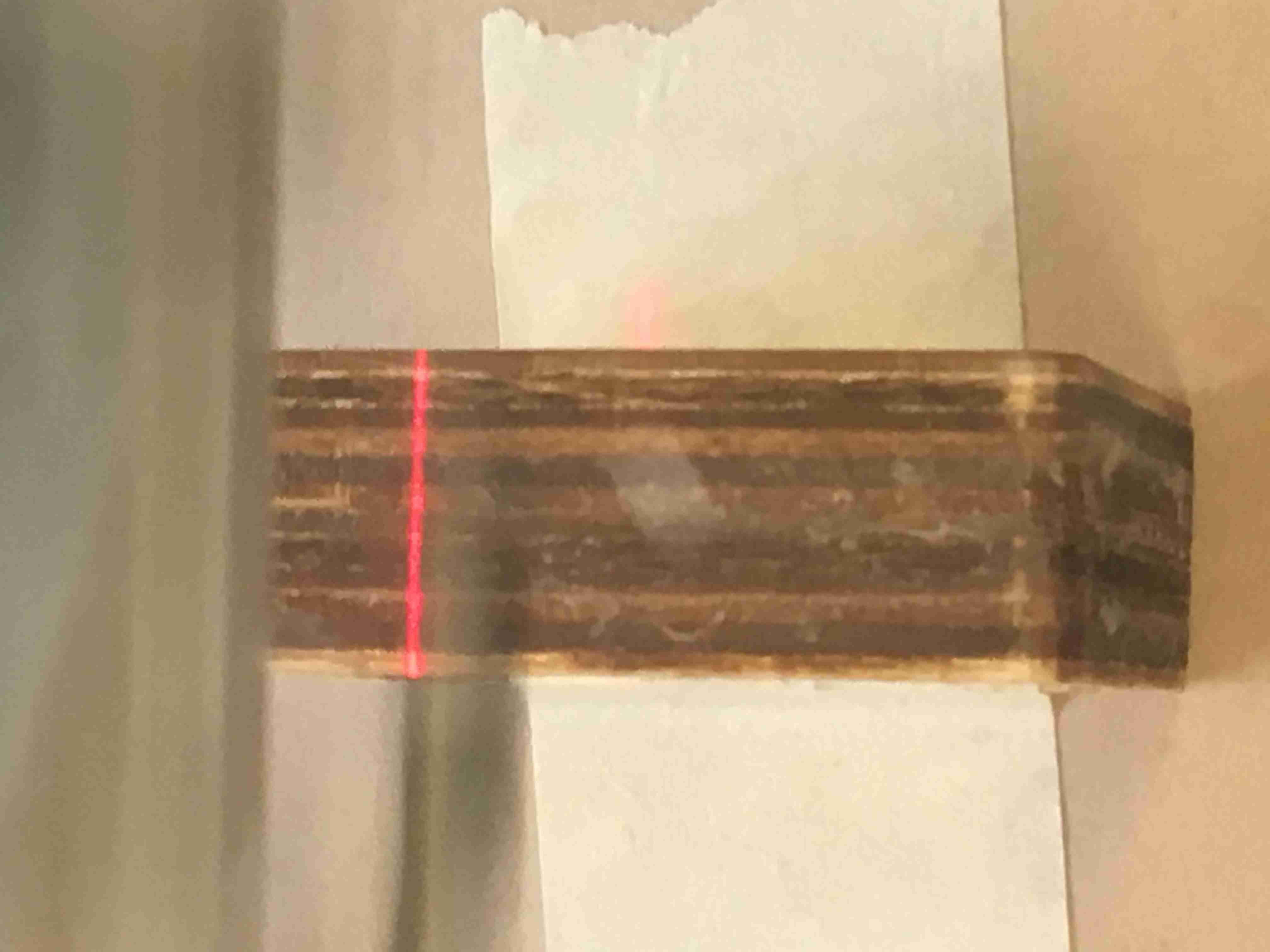
I first laser rastered the sides to ensure I knew where the holes should be. Just a light raster left a small small indentation that I used to guide my cuts
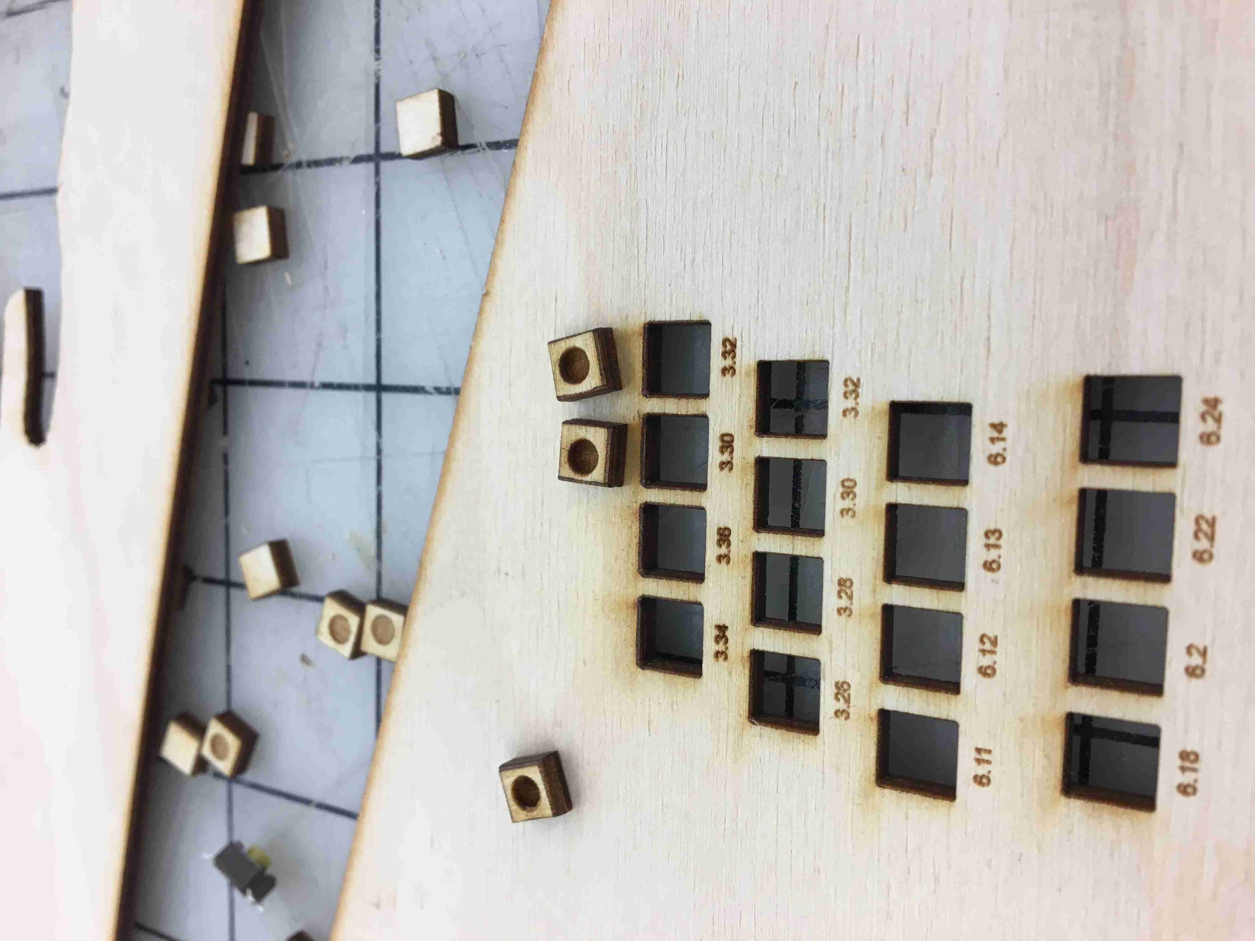
I then created a ton of cuts to pressure fit the button. I thought I could laser engrave the button, since it's not very thick,
but laser engraving is VERY low resolution. I got a rounded cut instead of a good cut. So I quit that failed project.
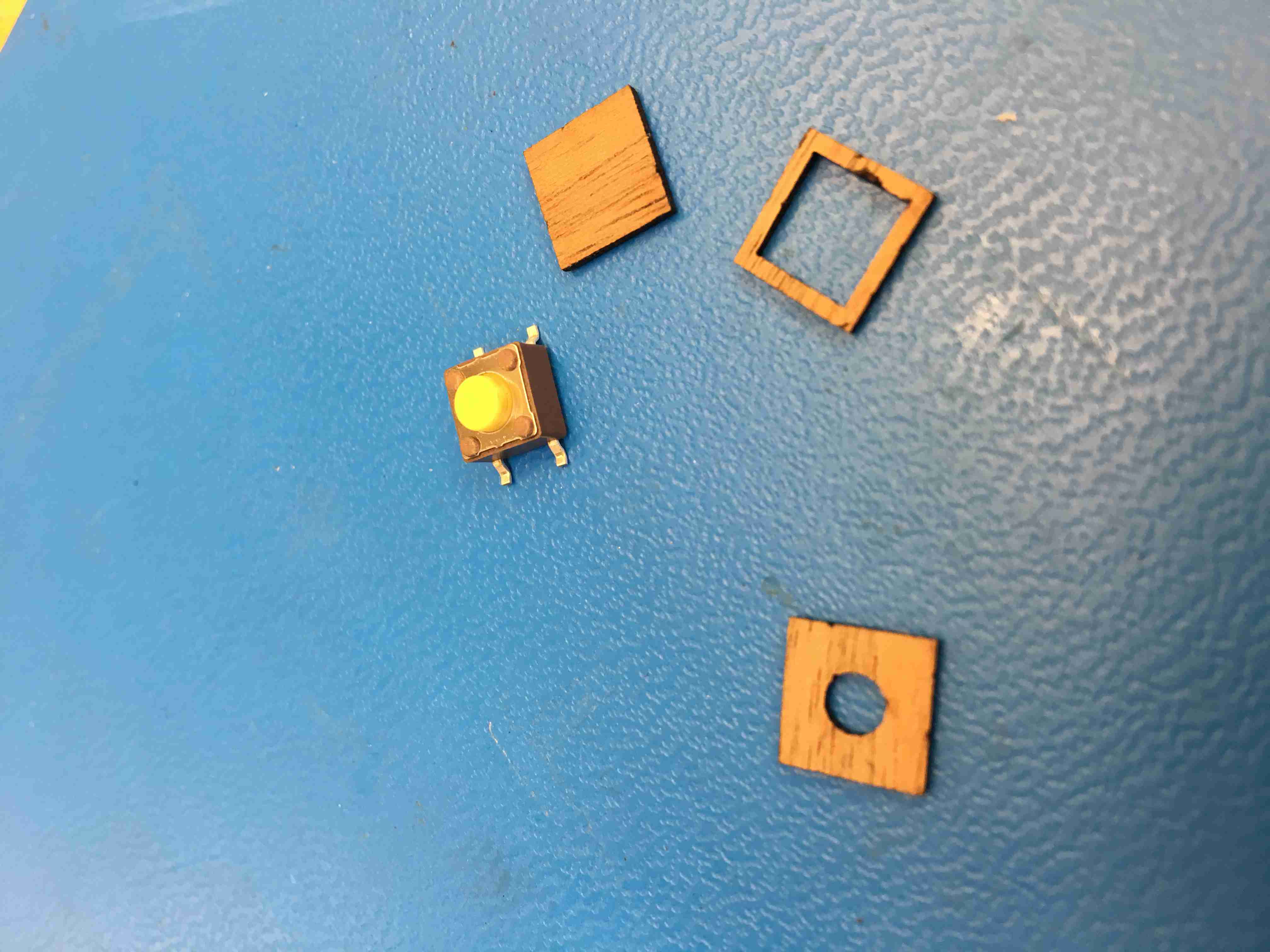
I just took slices of very thin 1mm wood and cut it so that the wooden button fit AROUND the piece. The middle piece was laser cut, and the bottom piece was sanded off until it fit.
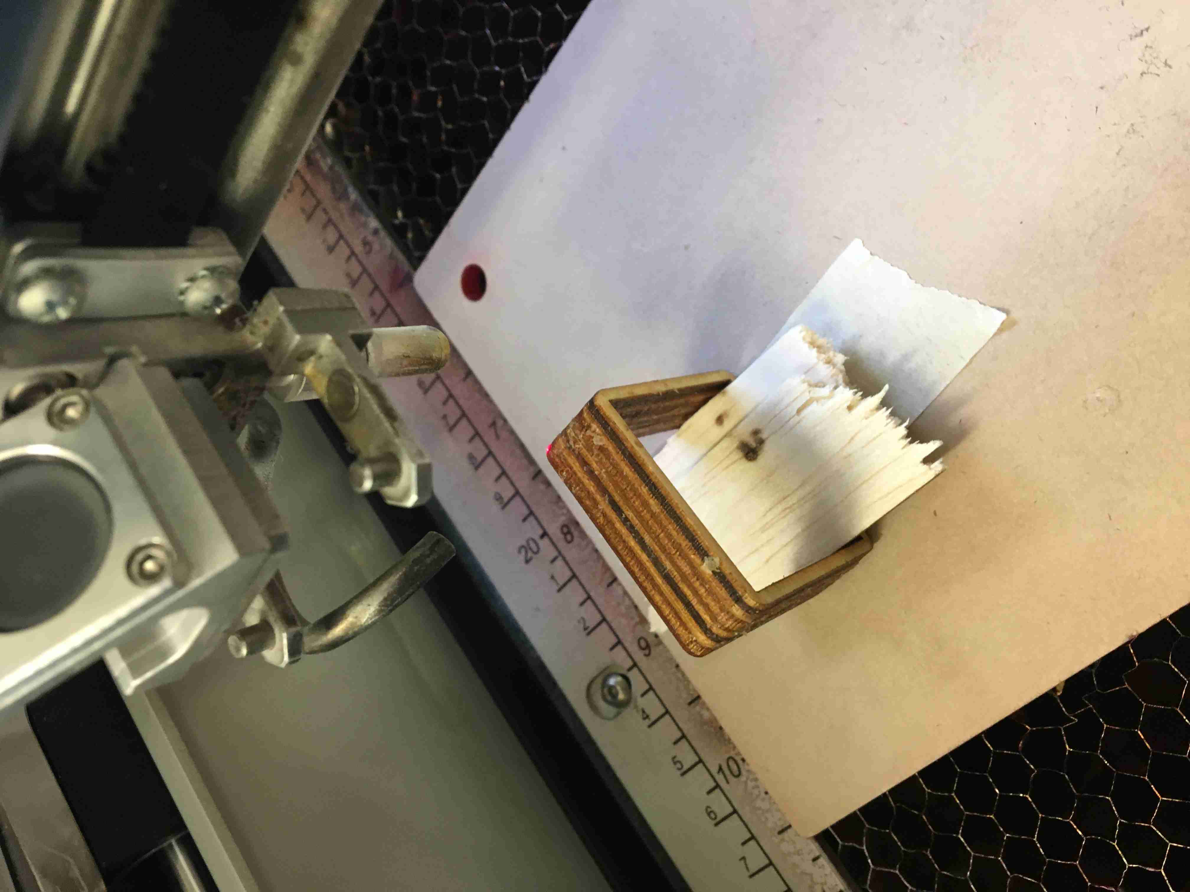
Don't forget your sacrificial layer of wood so that when it cuts through, it doesn't burn your piece!!
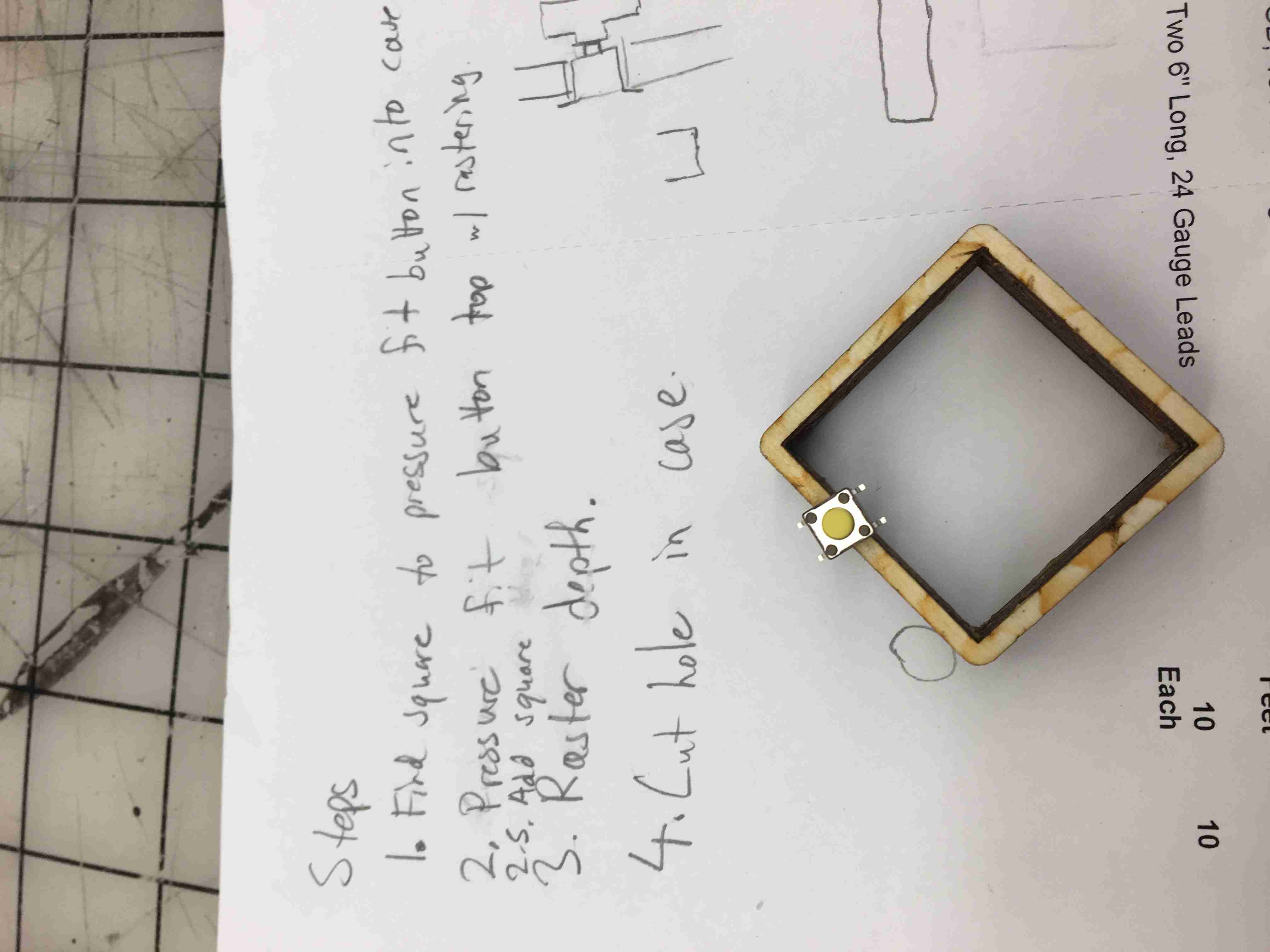
Just more Step by Step instructions for myself. I was losing a ton of sleep at this point, so I needed some structure beyond just my attempt to remember.
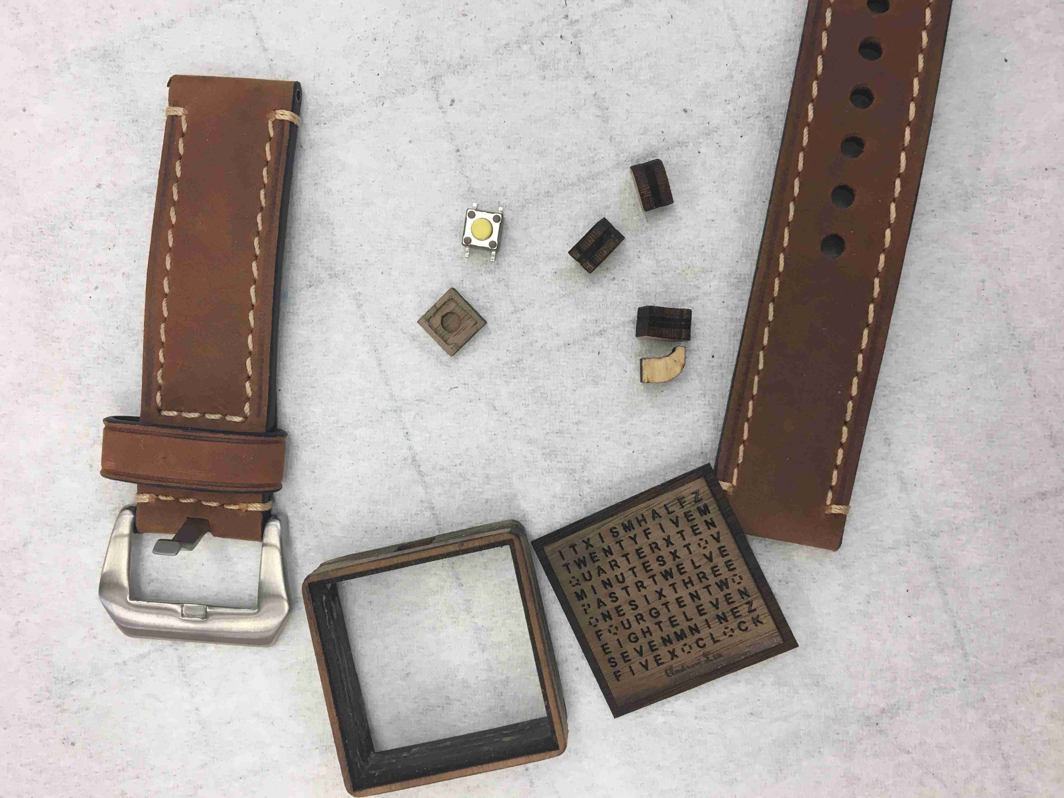
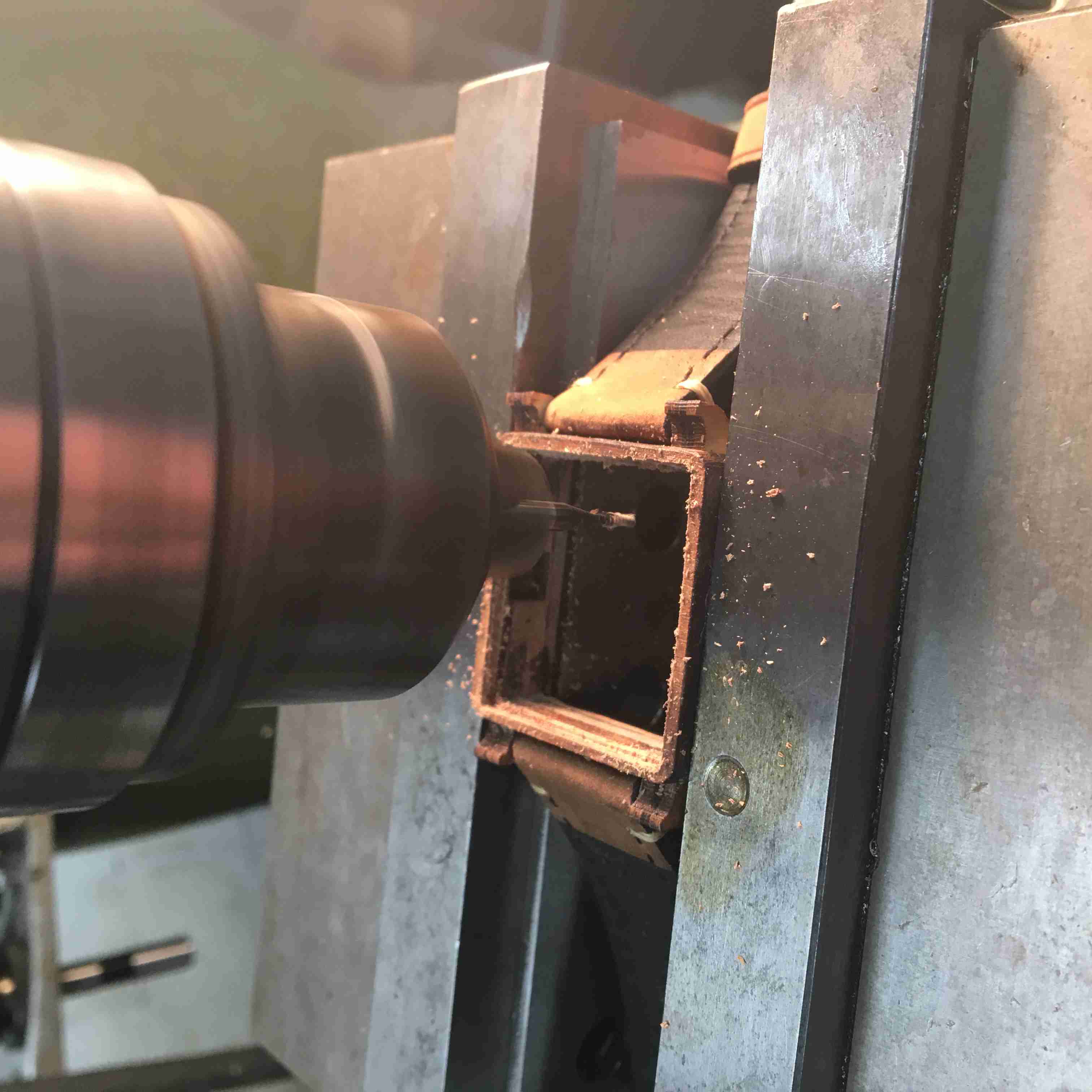
Everything brought together. I didn't assemble things until later. Not shown: Drilling 1mm holes into the legs.
That was easy. Just a milling machine, laser engraving the position of the hole, and one extra leg to drill through to ensure everything was aligned.
Now came time for the back case. I had to cut a small outline on the edge so that the pressure fit acrylic didn't fall through.
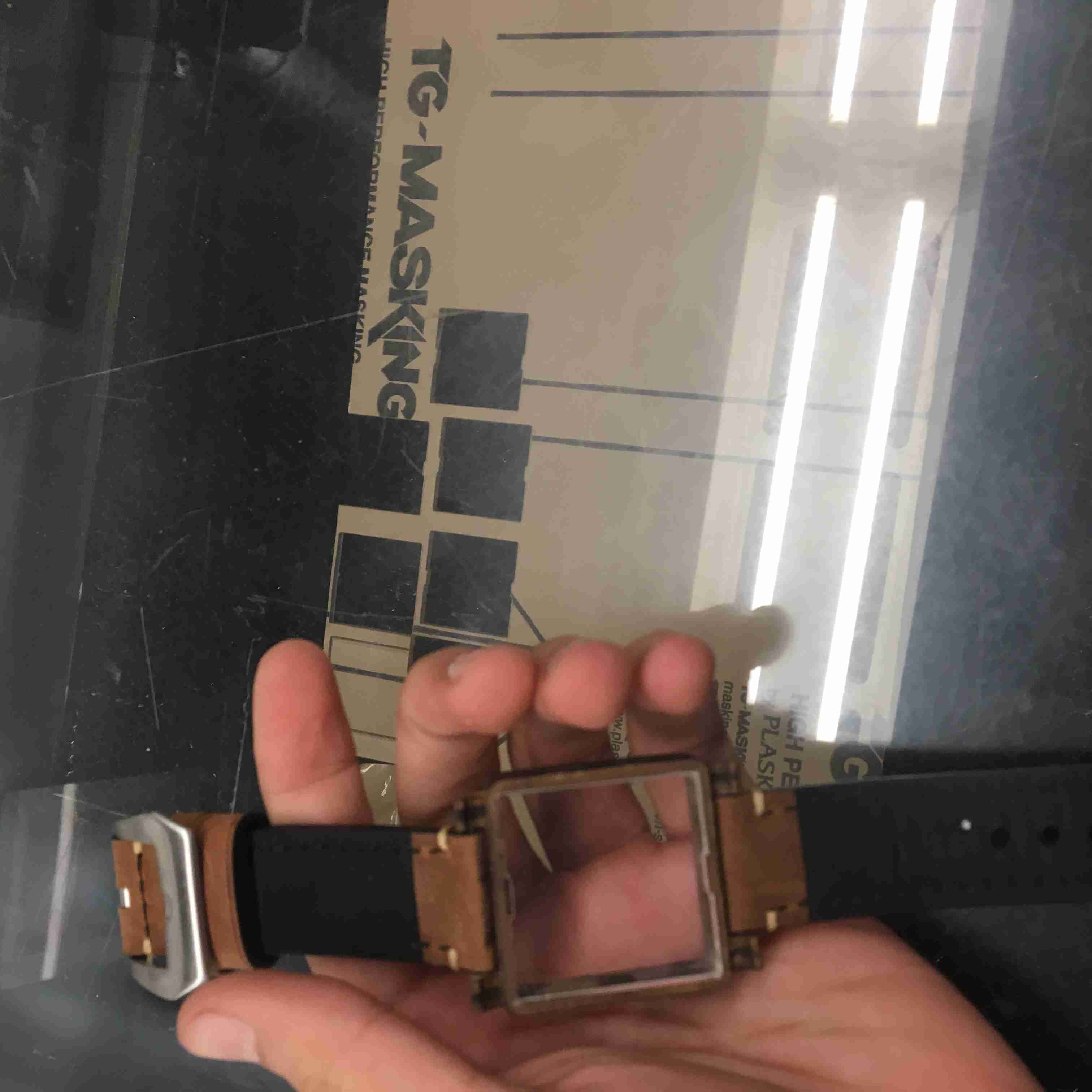
I laser cut out the back panel acrylic. Just a couple iterations before I got a good fit.
Becuase I used an imperfect CNC mill and I did the cut by hand.
Everything together. Looks kinda nice, right?
Circuits Circuits Circuits
A majority of this will be conversation, because a lot of this stuff doesn't have pictures. Let's talk math.The Circuit in Math
LEDs
The LEDs require a lot of thinking, although I definitely didn't think they did. If you use normal LEDs, you're not going to get the best brightness. In fact, you'll get like 5-8lcd if you use a 1.9V forward voltage green LED. Those are terribly lossy.
This is where Prof. Horowitz came in and told me to use galium nitride LEDs. They're better, but they require a 3V forward voltage. I would need two cell batteries and put them in series to get 6V, and then two diodes to get them down to 4.8V and choke the diode by only giving it 1.8V. Later on, it turned out I didn't need that whatsoever!
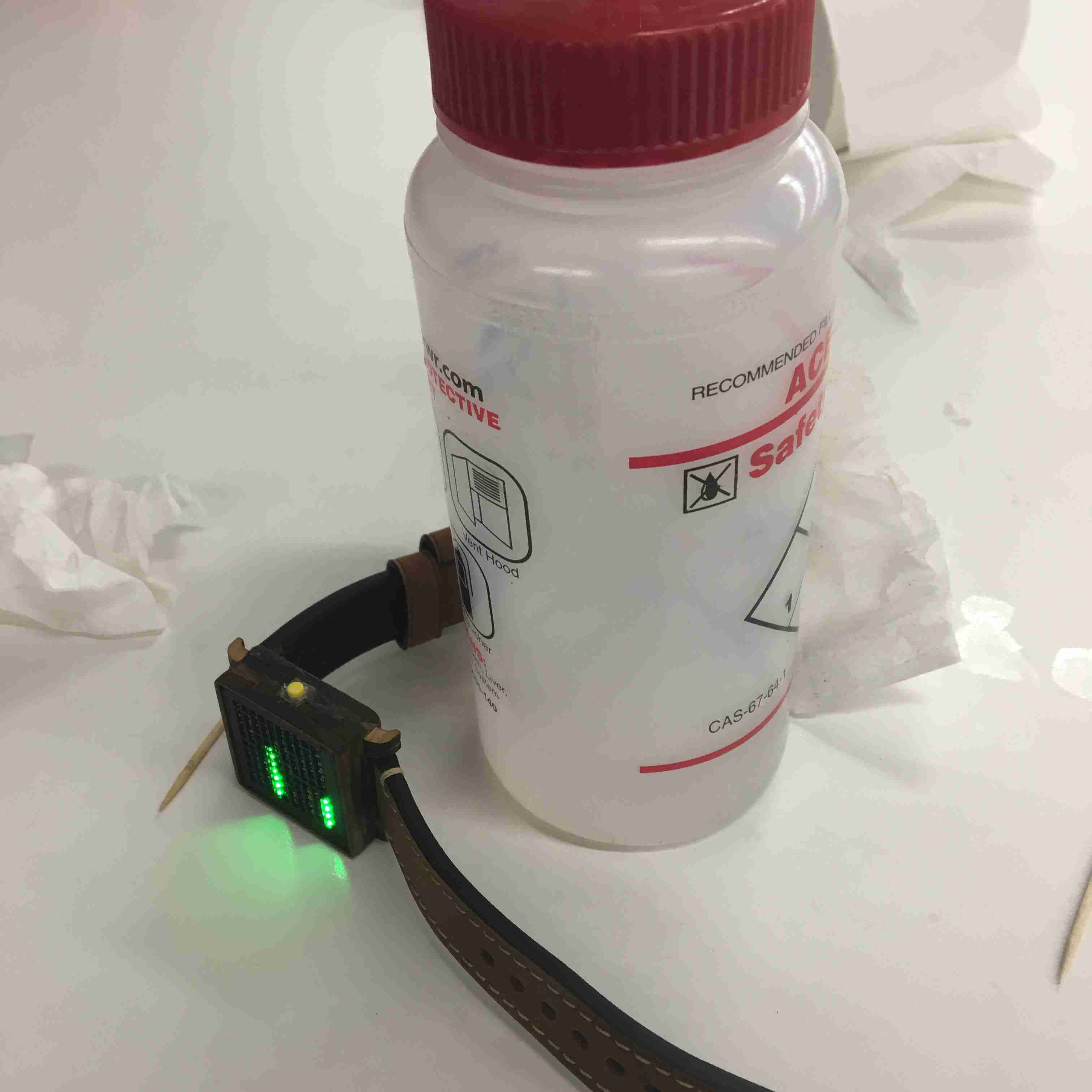
You see, an LED runs at 3V forward voltage at 5ma. That's hella bright though. It basically burns. Here's a picture of it running at 1ma.
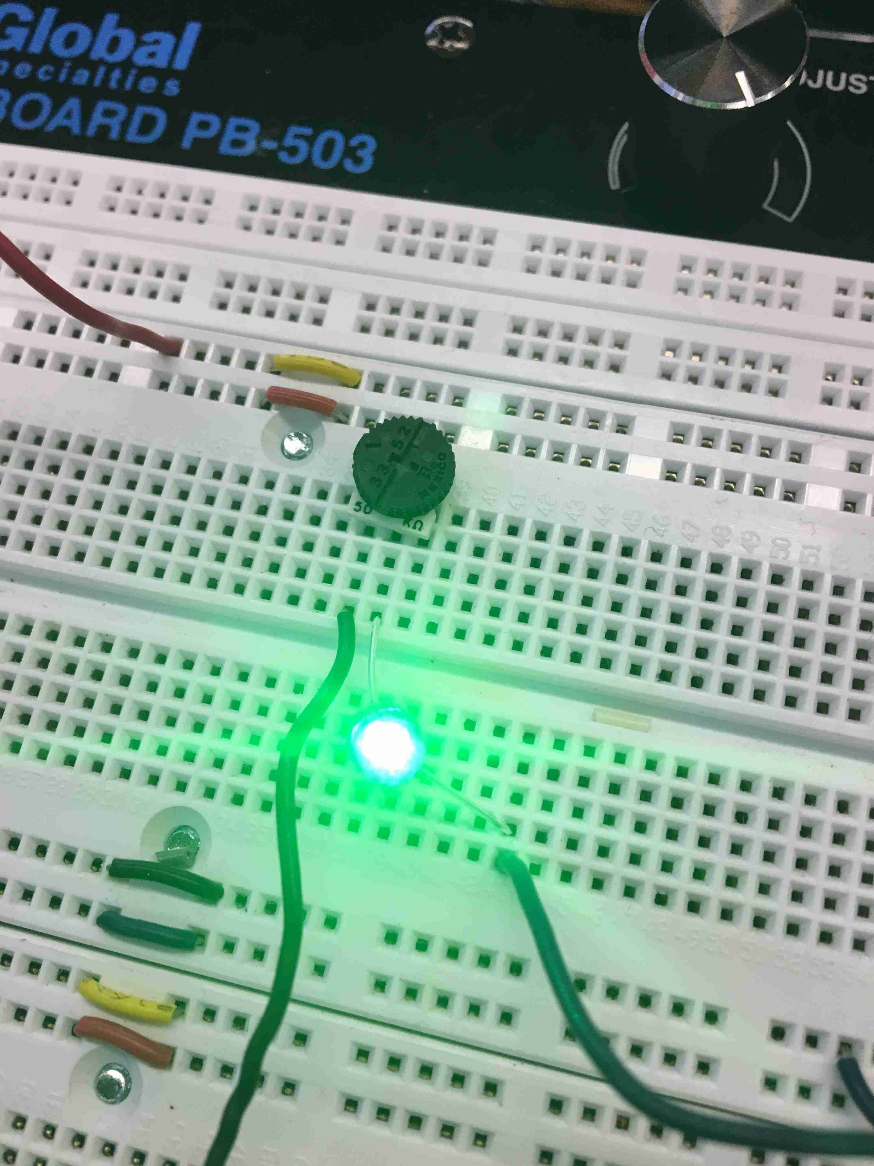
I was basically blind. These galium nitrides are great tho! I didn't realize until later that I didn't need 5ma, but just .1ma!
Well, guess what the voltage at .1ma is? Much lower than 2.8V, which is the nominal voltage of the battery cell! I can run it on just one CR2032 battery. Perfect!
Another big takeaway was that the CR1632, which is what I was planning on using, has a case just as as big as a CR2032 (the 16 and 20 represent diameter while the 32 represents height in mm)!! This was a miracle in disguise. The lifetime of the CR1632 is also 125mAH, which is much less than CR2032, which has lifetime of 230maH. More battery life means less nuisance for Andrew which means he complains to me less. Thank god.
Crystal Oscillator
A crystal oscillator, which is what keeps the time, has a specific load capacitance that it asks the user to connect. For mine, it was 7pF, but you ALSO need to add stray capacitance. The equation is as follows:
C_1, C_2 = 2 * C_L - 2*C_stray
The stray capacitance is around 2-5pF, depending on the layout of your board. If your crystal is very close to the signal, it's only around 2pF, but you can't have any digital signals connected close to it.
The layout of the board ended up being good enough (and my supplies were just scarce enough) that I guessed that I was around 2pF of stray capacitance.
Resistors and LED sides I've given a 35mm space, but a lot of that goes into design and structure due to the choice of it being wood. I therefore gave myself a 27.5mm x 27.5mm space for LEDs, meaning that I only have a 2.5mm x 2.5mm space for each LED + resistor, but include baffles and tolerances, and I only have a 2.25mm x 2.25mm (I was off in this calculation later on. I should've given myself only 2mm.)
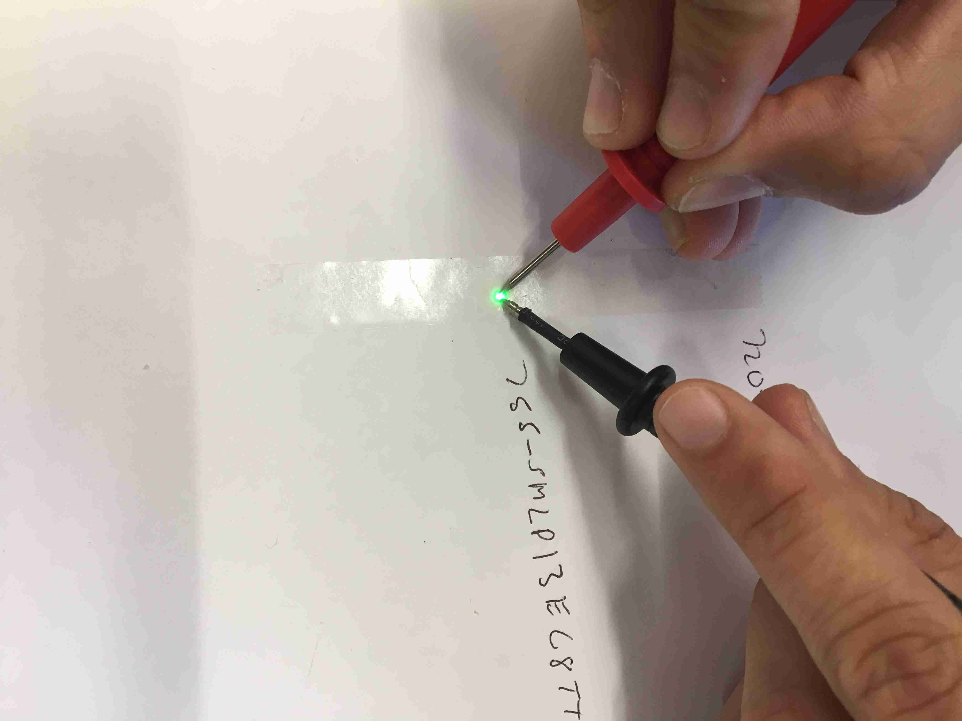
This means I'm stuck with the 0402 package. These things are .040" inches by .020" inches. I ended up buying two and comparing which one I wanted. For comparison of LEDs, check this out:
This is the LED I used. See how bright it is? Now let's compare it with a normal one.
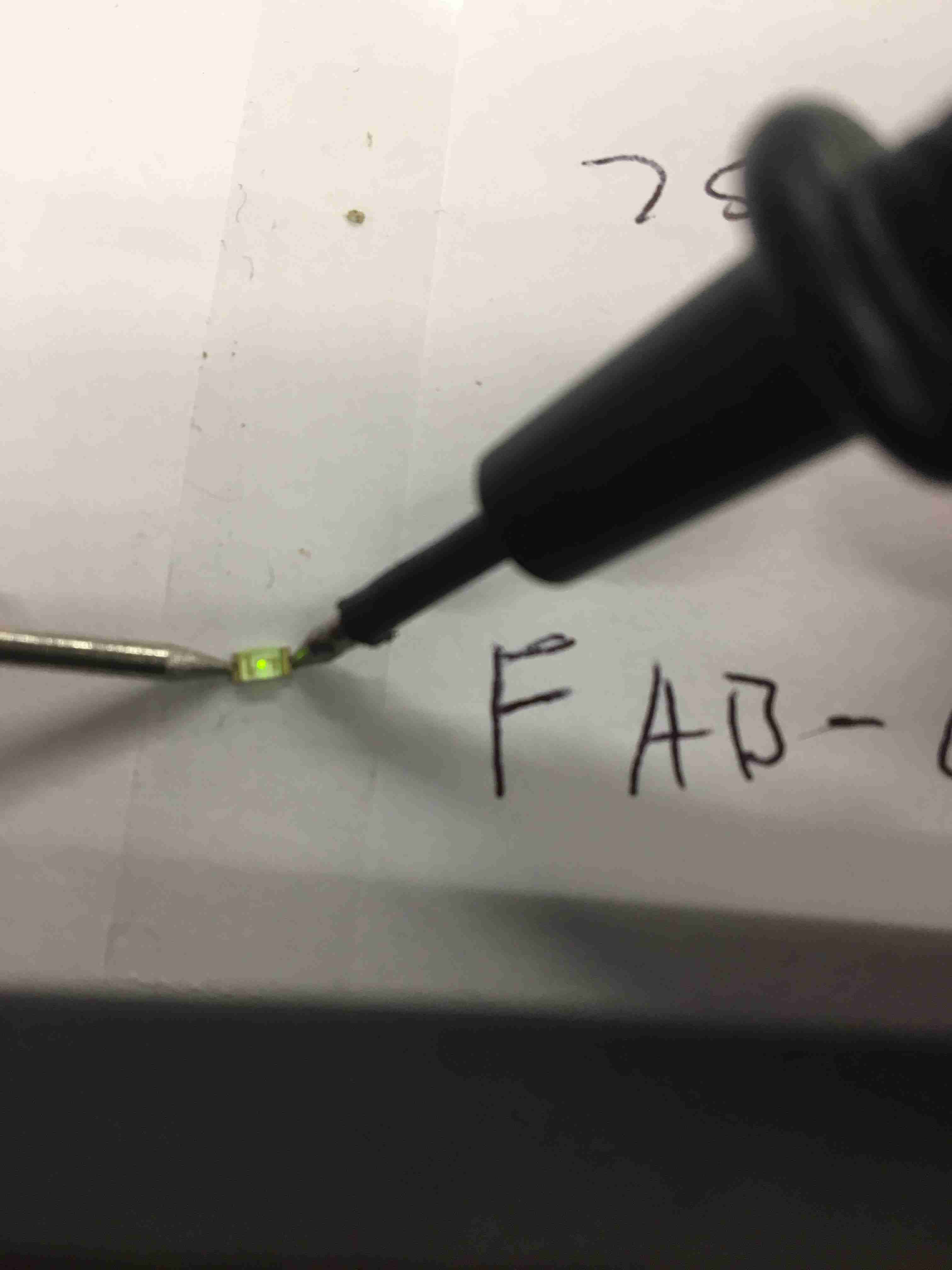
This is a normal fab LED. Can you even see that it's lit?
Now that I was done with LED choices, it was onto soldering. But first, circuit design.

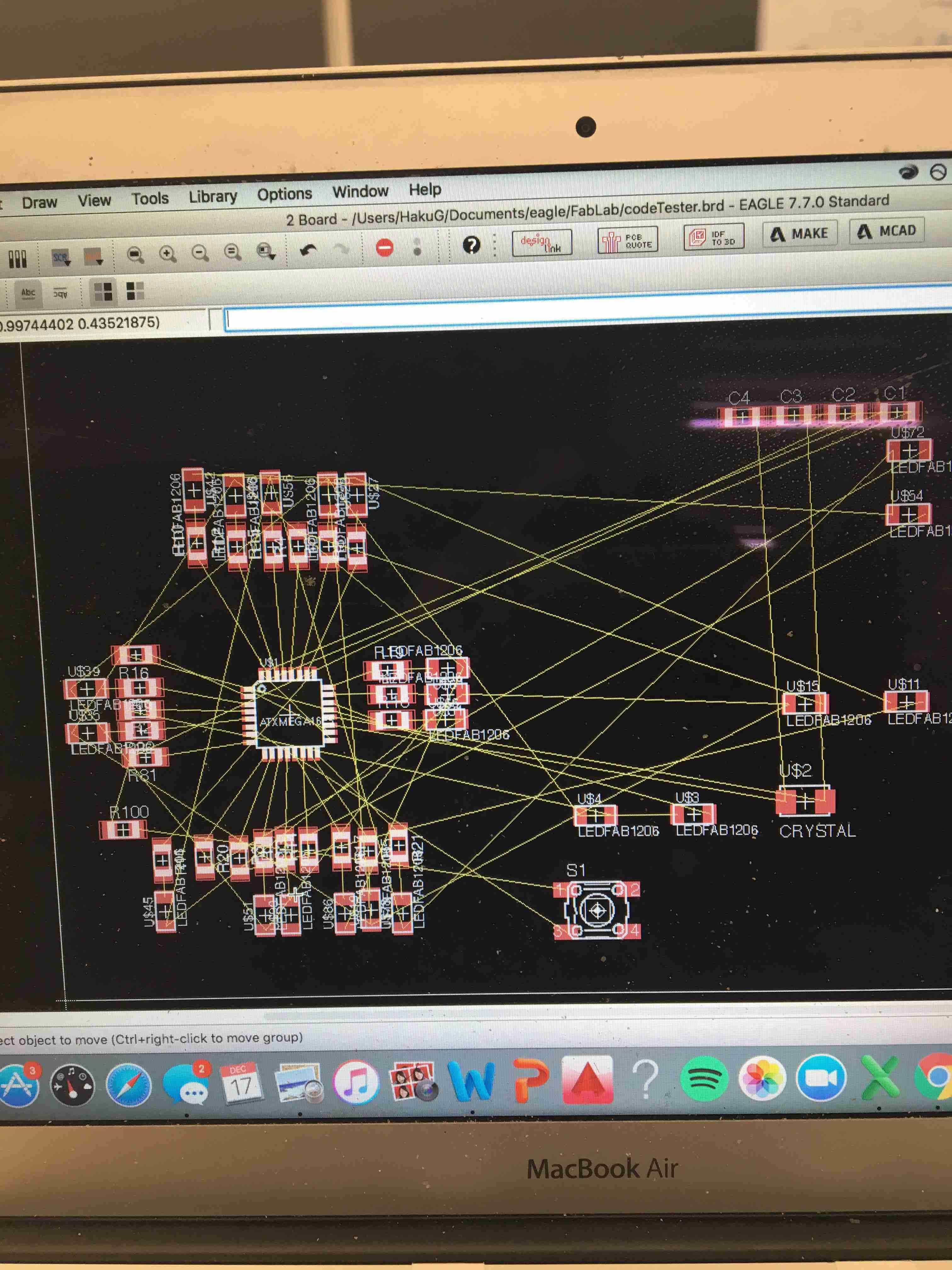
I moved everything into place after consulting the lovely lookup table here.
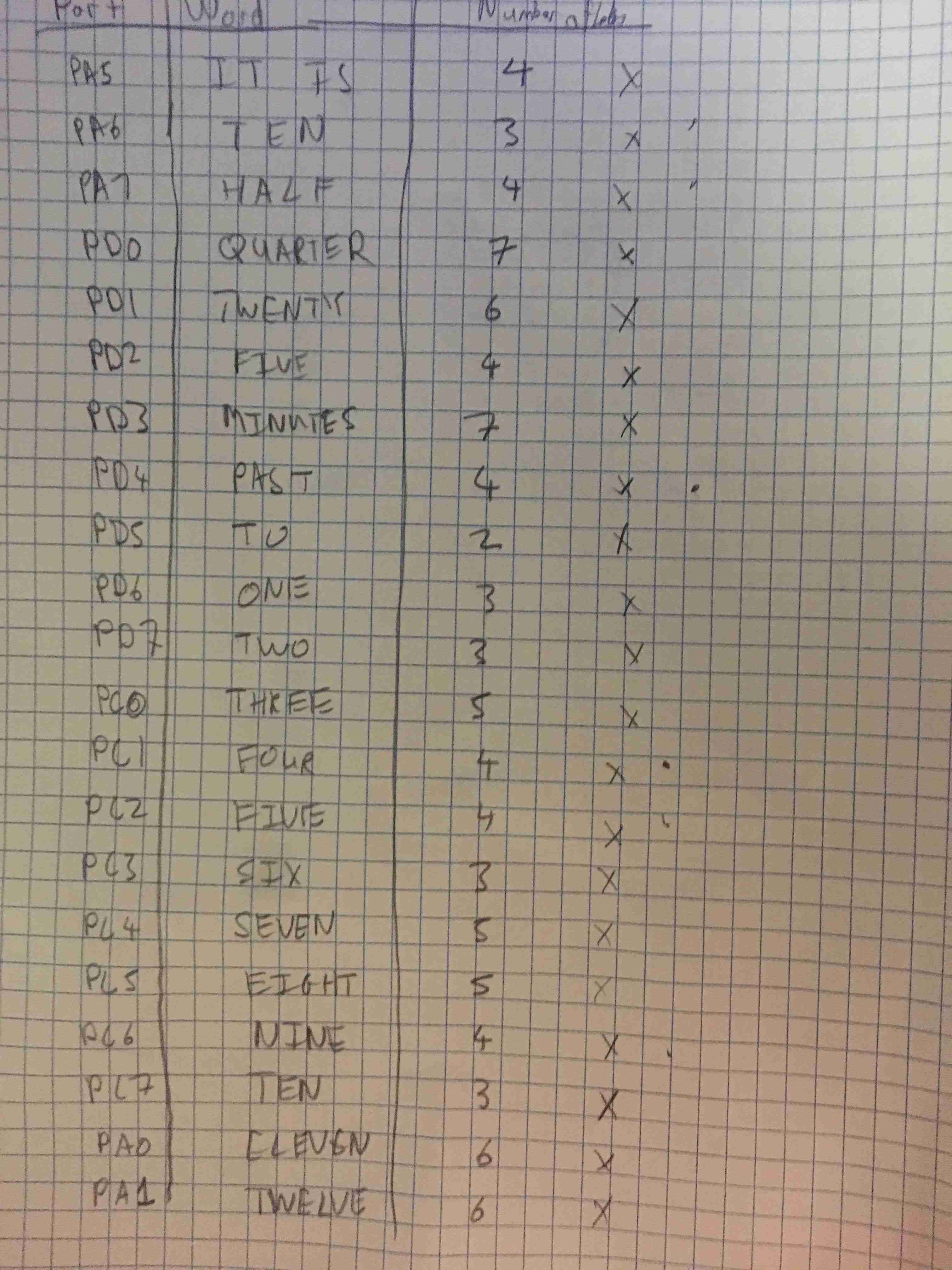
This helped me a lot. Just helped me figure out which words connected to which pins.
In the end, I had to scrap the entire thing for an excel sheet because of how often the pins moved around.
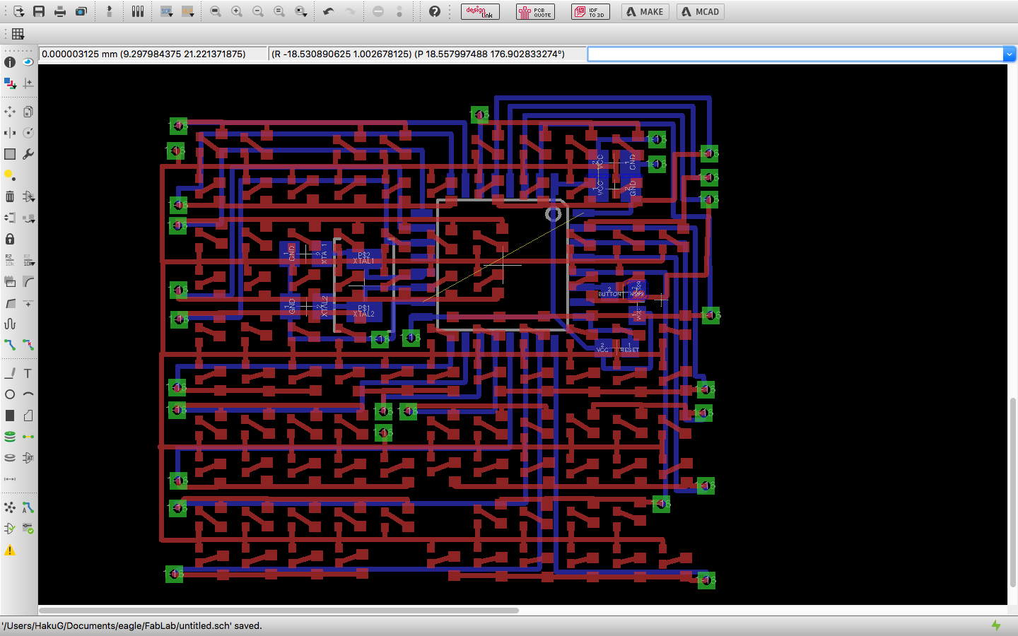
Woohoo. Done. Quite the ratsnest (HAHHAHA EAGLE JOKE). Funny story, I had eight hours to build this entire thing because I drew it on Monday, and if I was to get it by Fridya,
I needed to send the spec to the manufacturer by Tuesday at two.
At this point I'd like to thank Jim MacArthur for being a total bro and paying for the 1-Day shipping for my PCB, as well as for all my parts.
I don't know why this guy spent some of his slash fund on me, but it really means
a lot when the person you genuinely look up to as a mentor believes in you too.
He's legit my favorite person.
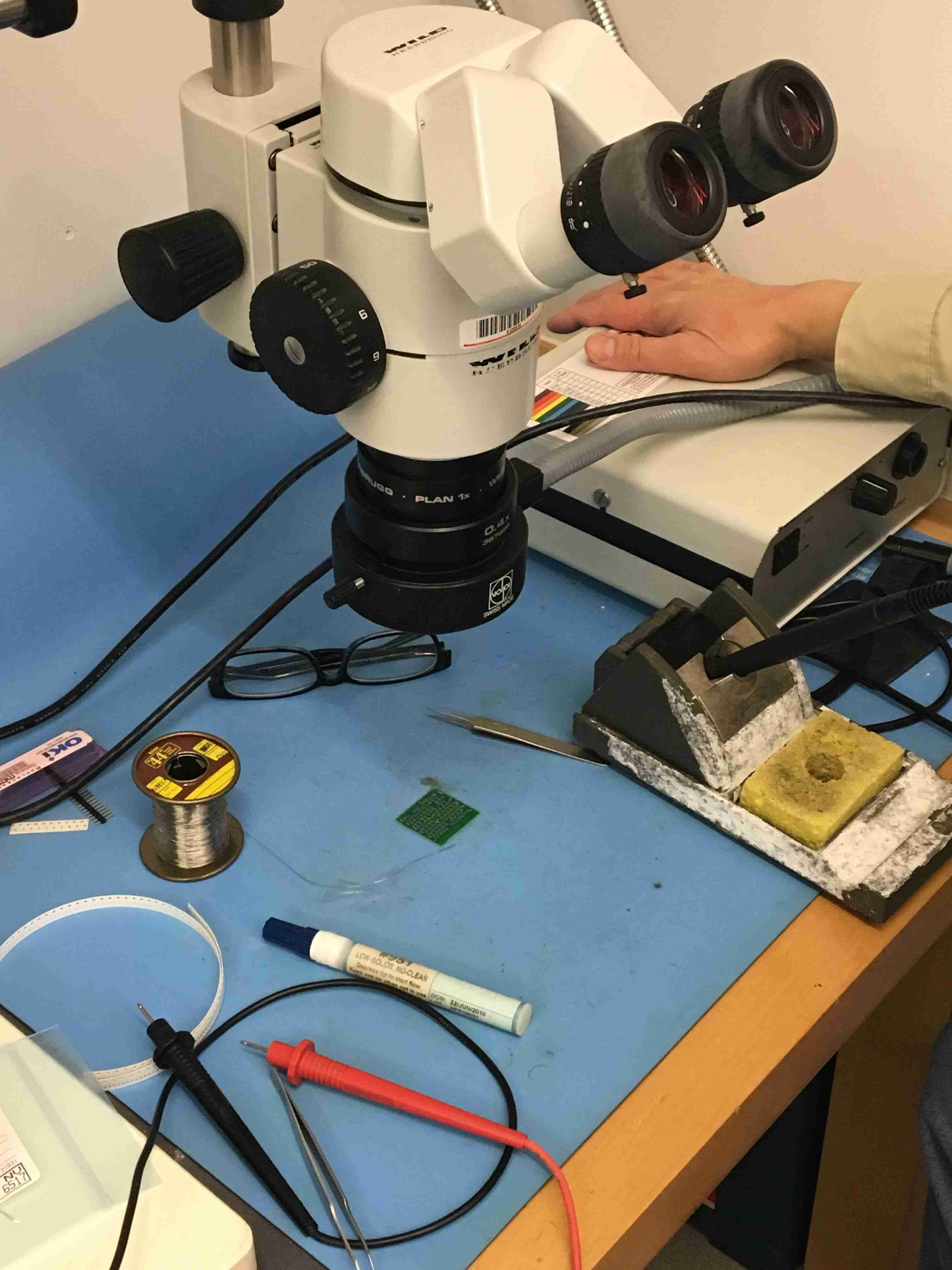
I got the PCB on Friday and had to do all the soldering in a couple hours. Here was my set-up.
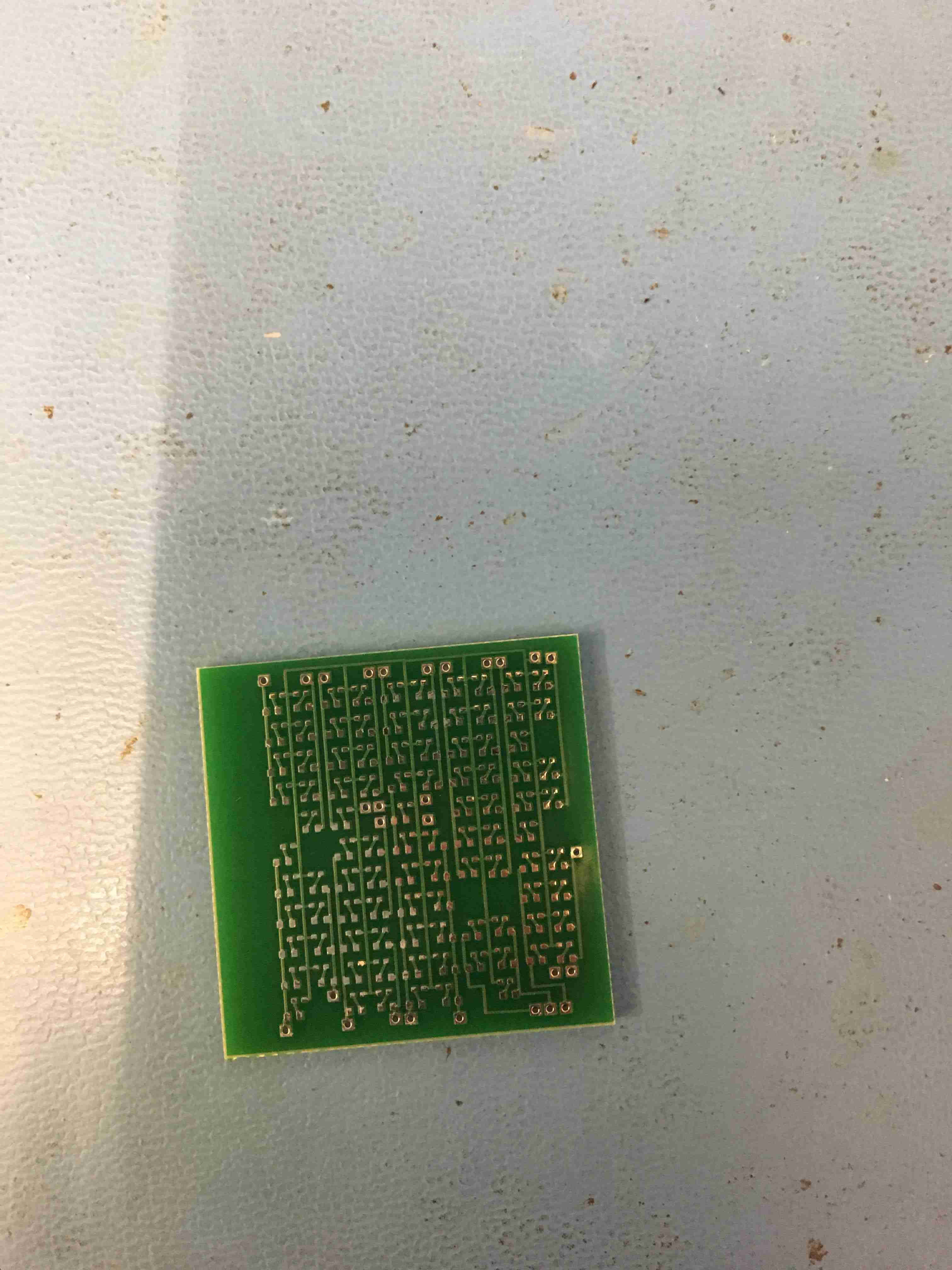
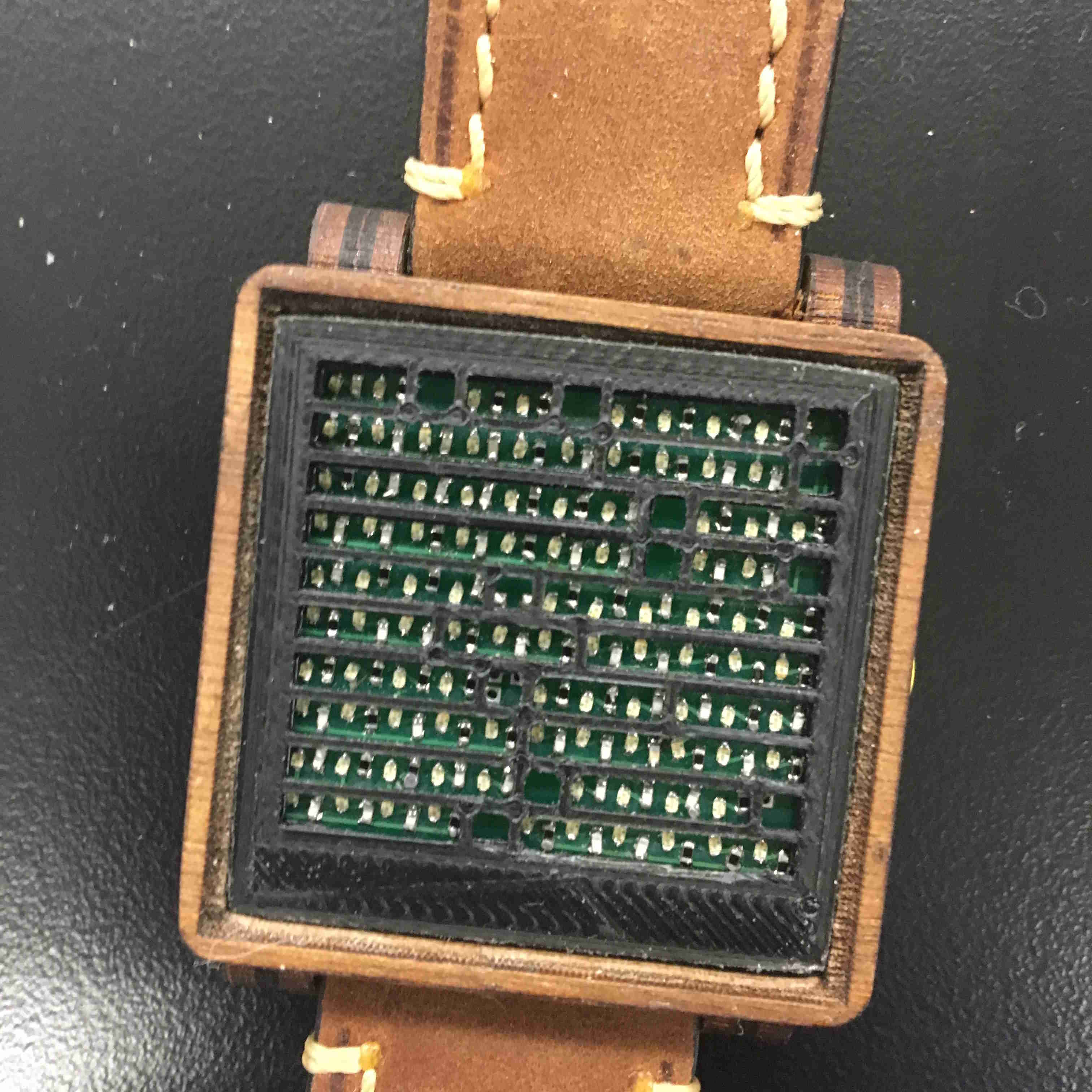
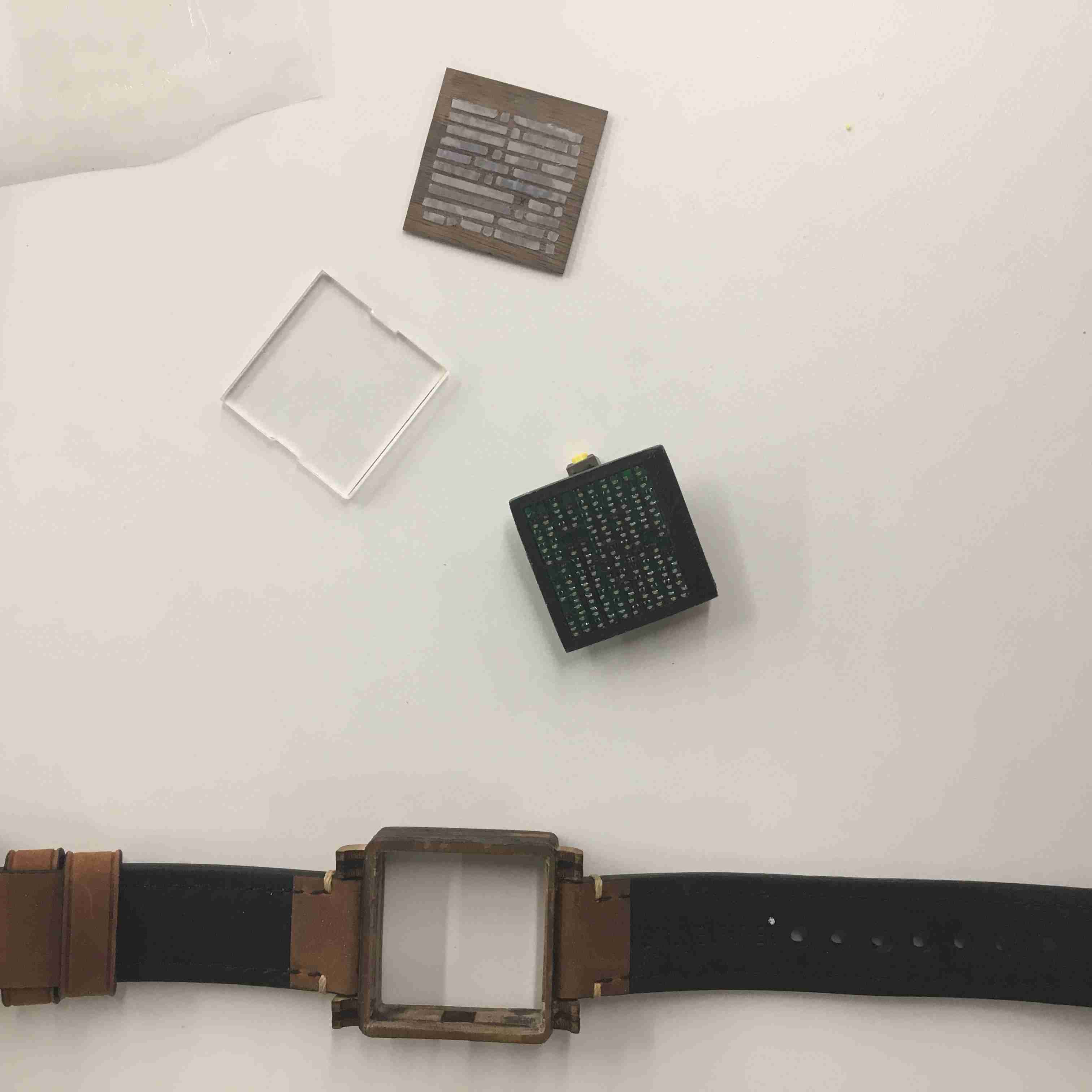
Here is the bare PCB. It's 32mm by 32mm. It needs to fit ~100 leds lol.
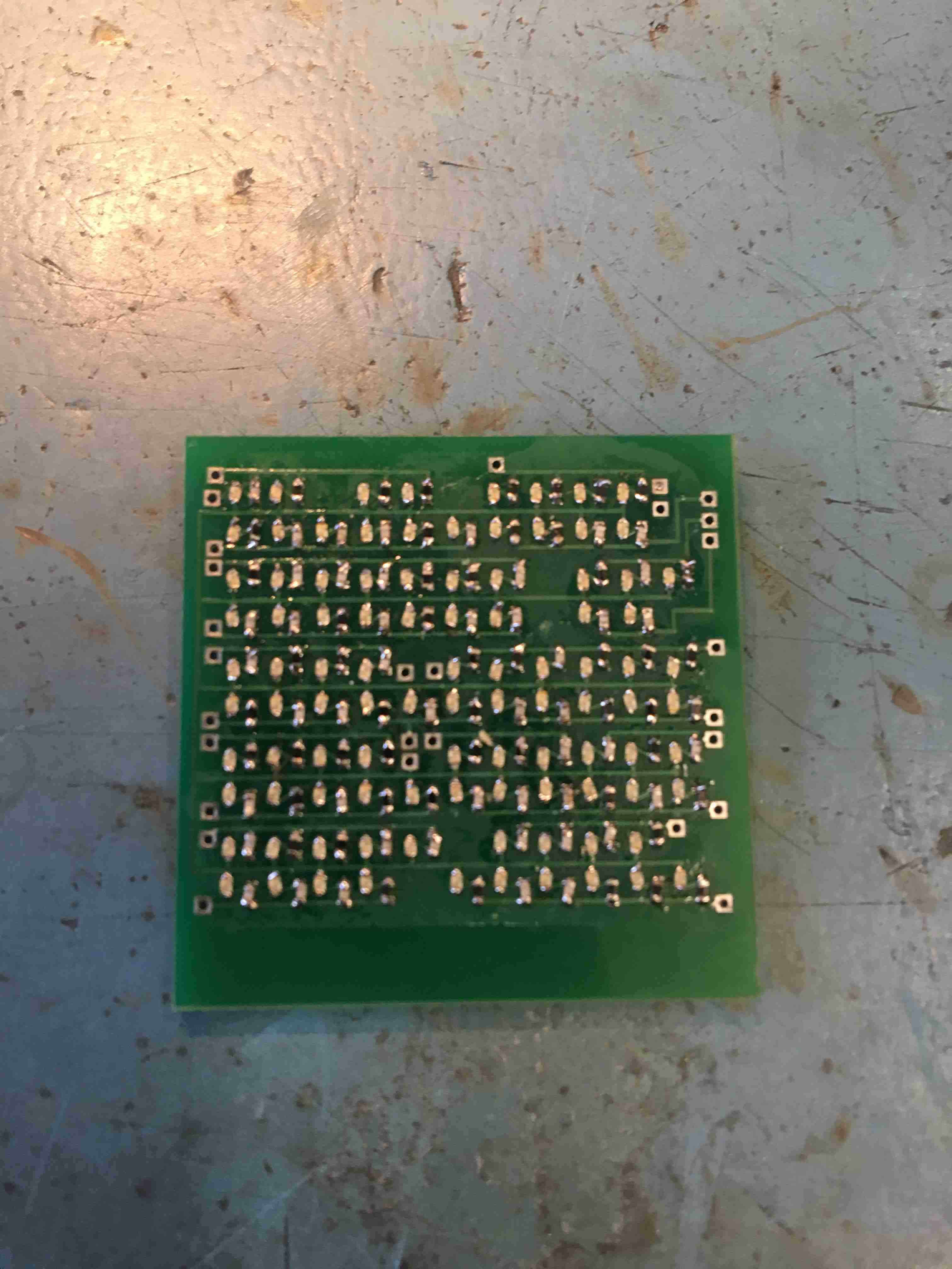
Here are the finished LEDs. God I love this. Soldering is so calming, I walked in super stressed and walked out chill AF.
I also made a Prototype Board to test the programming portion. It was an exact copy of the original board in terms of connections.

I could just mill out this board easily.
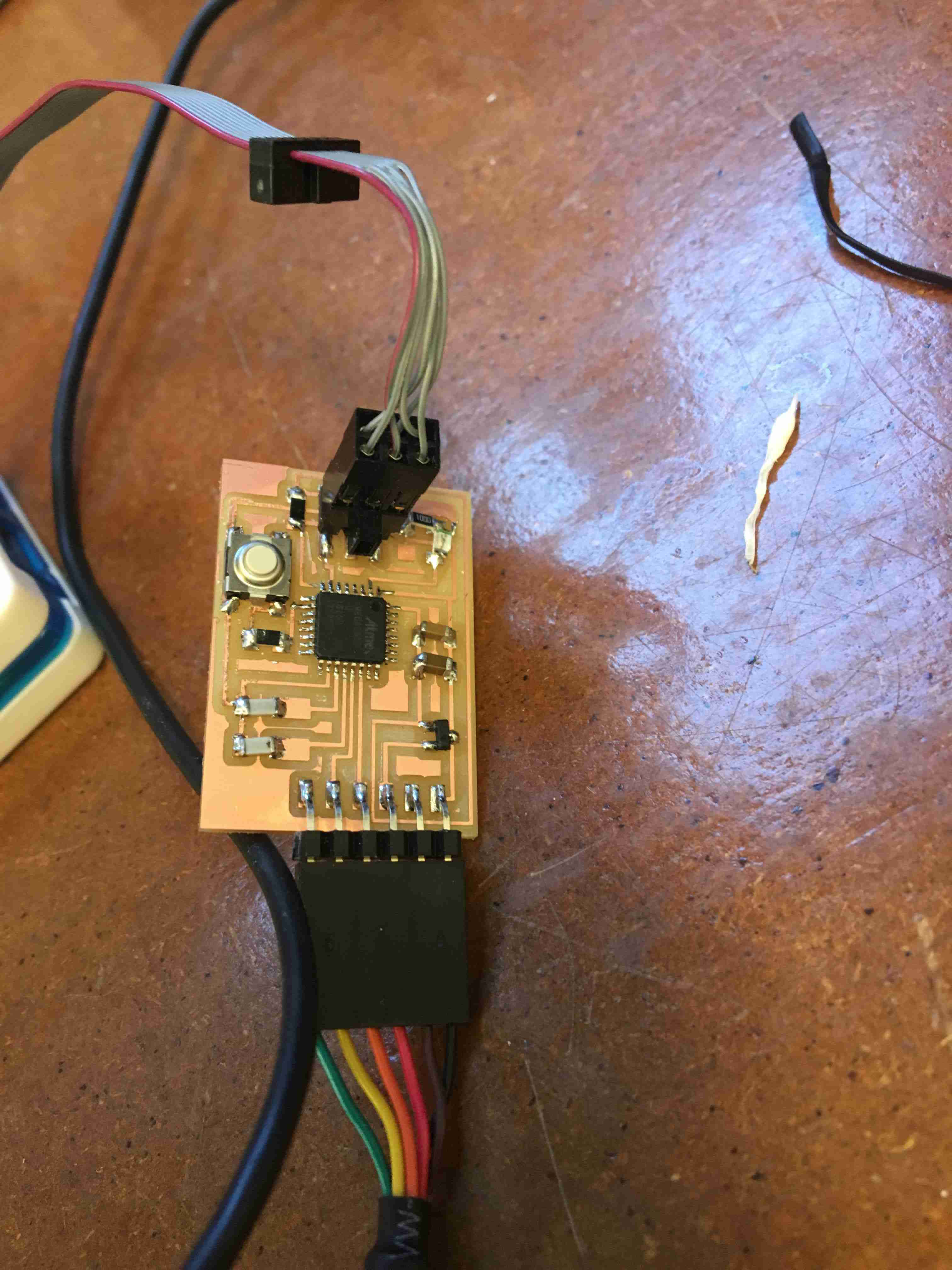
I made one more prototype board with a serial output so I could test the logic in my code.
Now that it's all set up, let's talk about the code.
Now that it's all set up, let's talk about the code.
Embedded Programming. Let's do this VPORT.
SKIP THIS SECTION IF YOU DON'T LIKE EMBEDDED PROGRAMMING
Programming Programming an ATXMEGA is tough because it requires a PDI interface. This means that normal AVRISPs may not work, but you can find a workaround sometimes. We use the command atmelice_pdi for programming. I still need to check if this can be the same for other atmel ISPs. VPORT
Let's talk about VPORT. VPORT is a faster way of turning on and off an LED. I have no idea why VPORT exists, but it does. Hence, we use ATXMEGA's VPORTS in order to be faster. However, we can't set the button's output to be the VPORT, hence we do the following:
VPORTA.OUT = 0xFE;
clear(VPORTA.OUT, 0);
VPORTC.OUT = 0xFF;
VPORTD.OUT = 0xFF;
VPORTA.DIR = 0xFE;
VPORTC.DIR = 0xFF;
VPORTD.DIR = 0xFF;
Making it sleep.
This part was pretty difficult to figure out, but in the end it was just a simple command. What we want to do is make it sleep, and then when it wakes up to an interrupt
SLEEP.CTRL = SLEEP_SMODE_IDLE_gc;
SLEEP.CTRL |= SLEEP_SEN_bm;
sei();
sleep_cpu();
SLEEP.CTRL &= ~SLEEP_SEN_bm;
Real Time Clock
Again, just more synchronization.
OSC.XOSCCTRL |= OSC_XOSCSEL_32KHz_gc;
OSC.CTRL |= OSC_XOSCEN_bm;
do {
/* Wait for the 32kHz oscillator to stabilize. */
} while ( ( OSC.STATUS & OSC_XOSCRDY_bm ) == 0);
CLK.CTRL |= CLK_SCLKSEL_XOSC_gc;
/* Set external 32kHz oscillator as clock source for RTC. */
CLK.RTCCTRL = CLK_RTCSRC_TOSC_gc | CLK_RTCEN_bm;
Button Set-up
Access the interrupt through this:
ISR(PORTA_INT_vect)
Set up the interrupt through this
/* Pull up button port */
PORTA.PIN0CTRL = PORT_OPC_PULLDOWN_gc | PORT_ISC_RISING_gc;
/* Say that the interrupt is equal to 0 */
PORTA.INTMASK = PIN0_bm;
/* Create a low level interrupt */
PORTA.INTCTRL = PORT_INTLVL_LO_gc;
QUICK NOTE ABOUT READING DATASHEETS FROM ATXMEGA: You have to figure out if the register you're setting is a GC (group config) or a bitmap(bm). You set registers like this: PORTION.REGISTER |= PORTION_REGISTER_SECTION_bmorgc.
FINAL ASSEMBLY: THIS IS HOW WE GET HYPEEEDDD
The embedded programming part was boring, I know. We're back to fun pictures!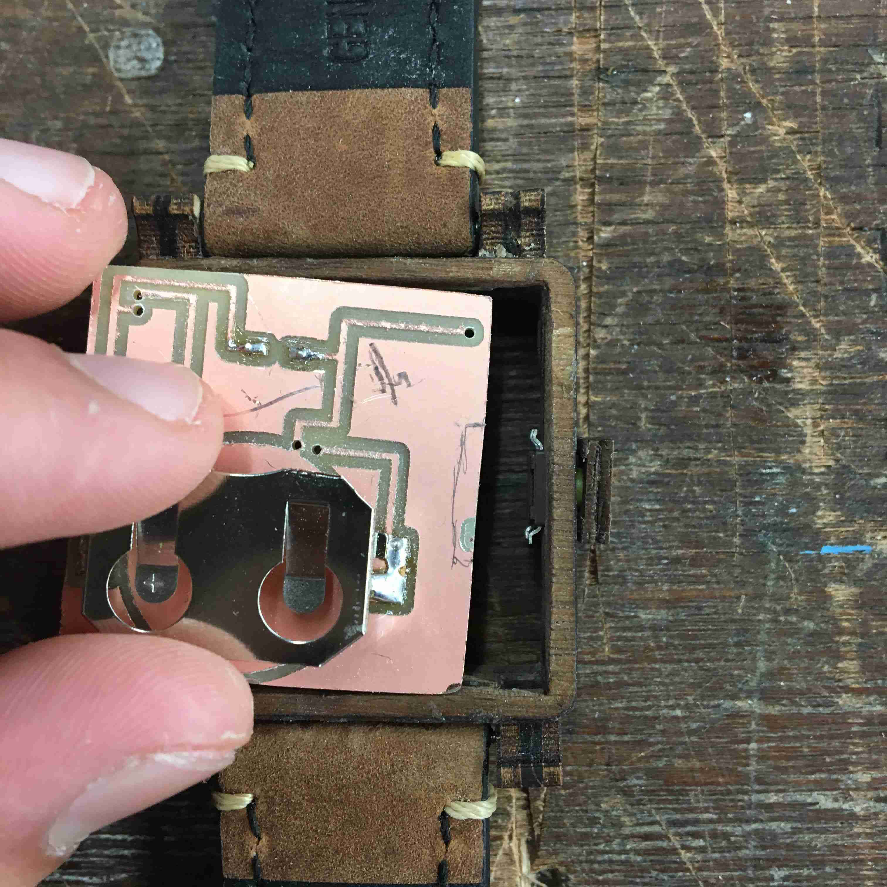
We started with a very complex way to connect everything. It was honestly pretty stupid, thinking back to it. The idea was to cut holes in the
copper cutout and connect holes to the through-holes in the circuit board underneath. Cool idea, but impractical.
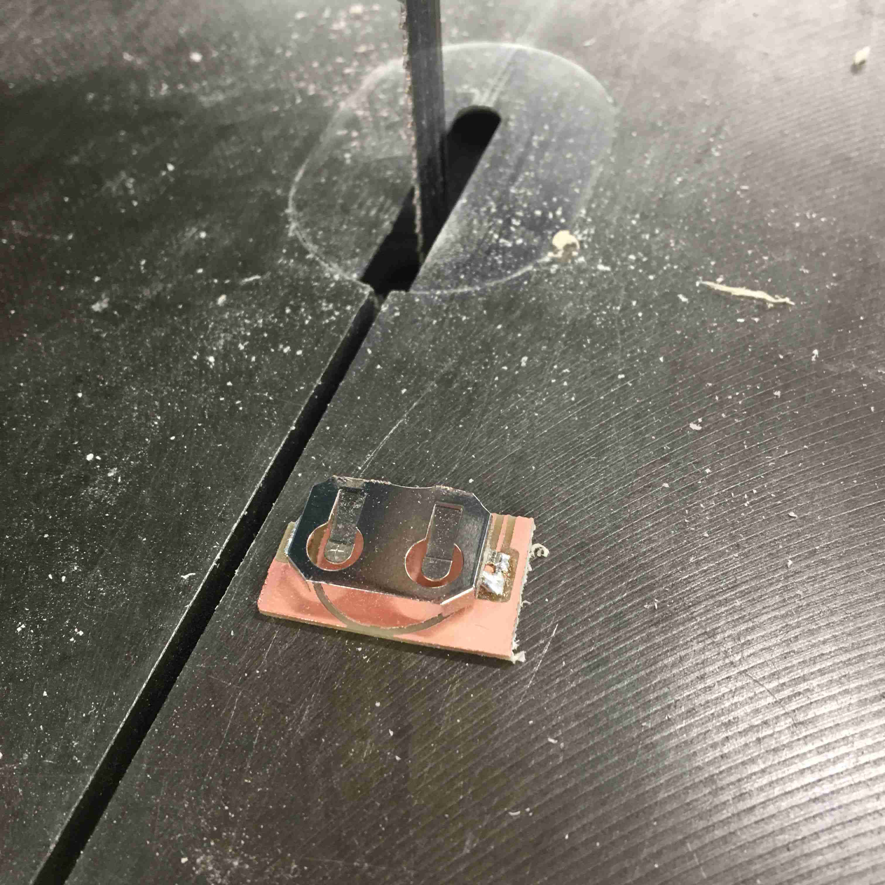
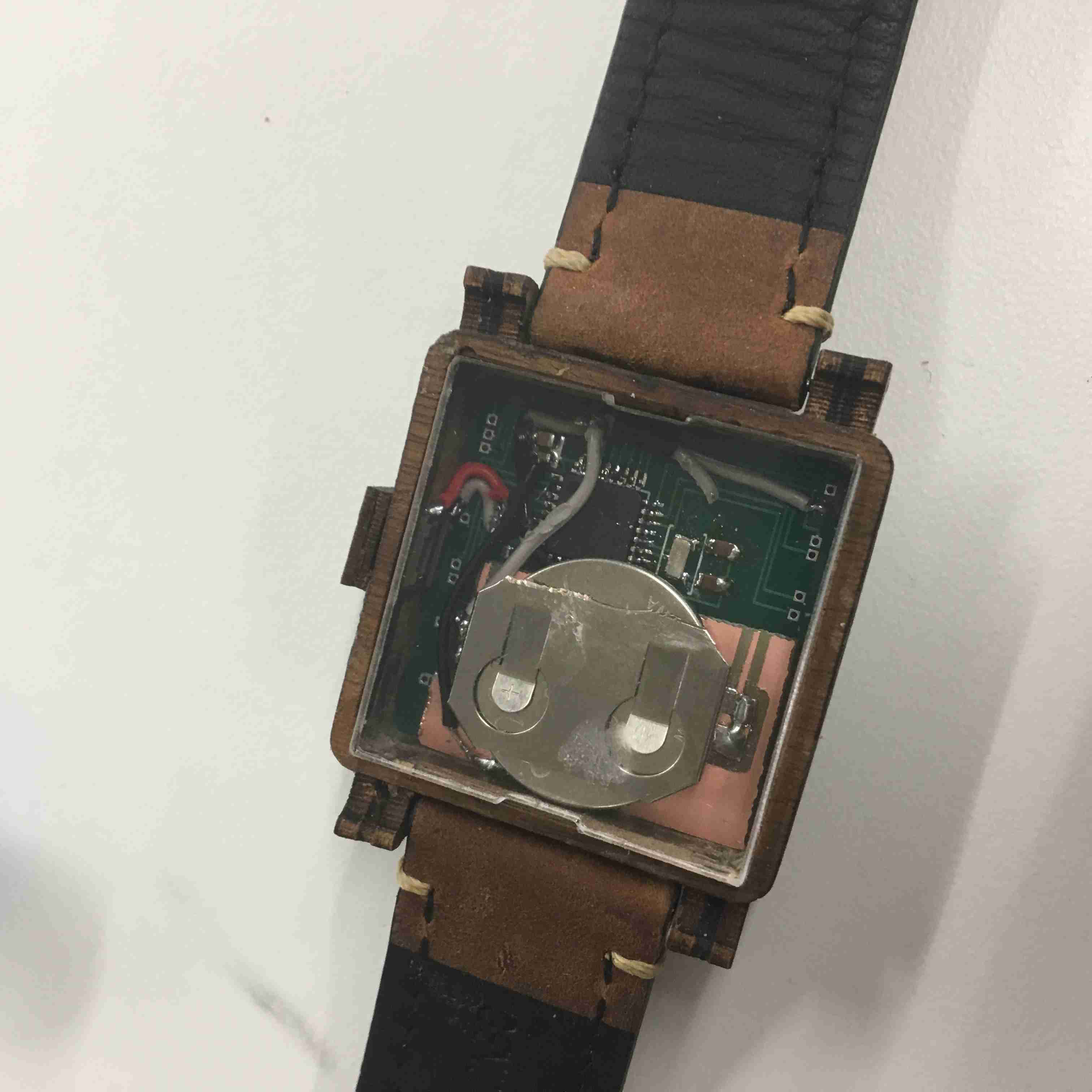
After facing too much difficulty, I decdied to screw it. I used a bandsaw and just took out the battery
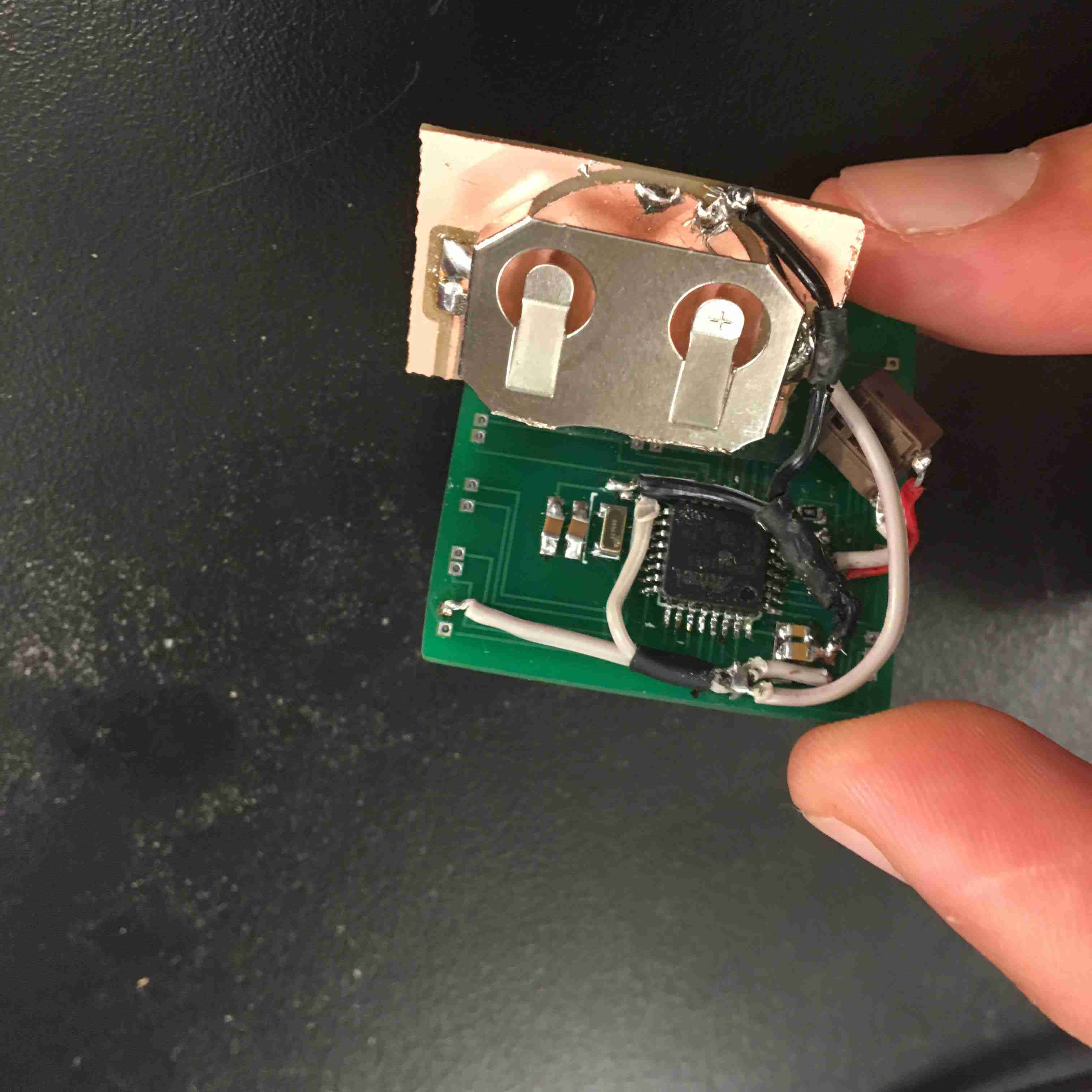
I connected everything as so. Note to self: the button of the buttoncase is ground, NOT VCC.

After around five hours of attempting to understand how to place the battery in, it worked! Thank the gods.
Everything was pressure fit as well. Not too bad of a process. =P.
Just adding the pressure fit pieces on the other side. Almost done!!!

Here's a sideview of everything!
THE EMERGENCY STORY: While everything is pressure fit, I add in super glue and wood glue for extra protection. The problem
was that the super glue actually got onto my button and sealed it down and bolted it to the case. I scrambled google
and found that acetone dissolves super glue. I soaked the button in acetone, and boom. Back to working again. Miracle. Seriously, a freaking miracle.
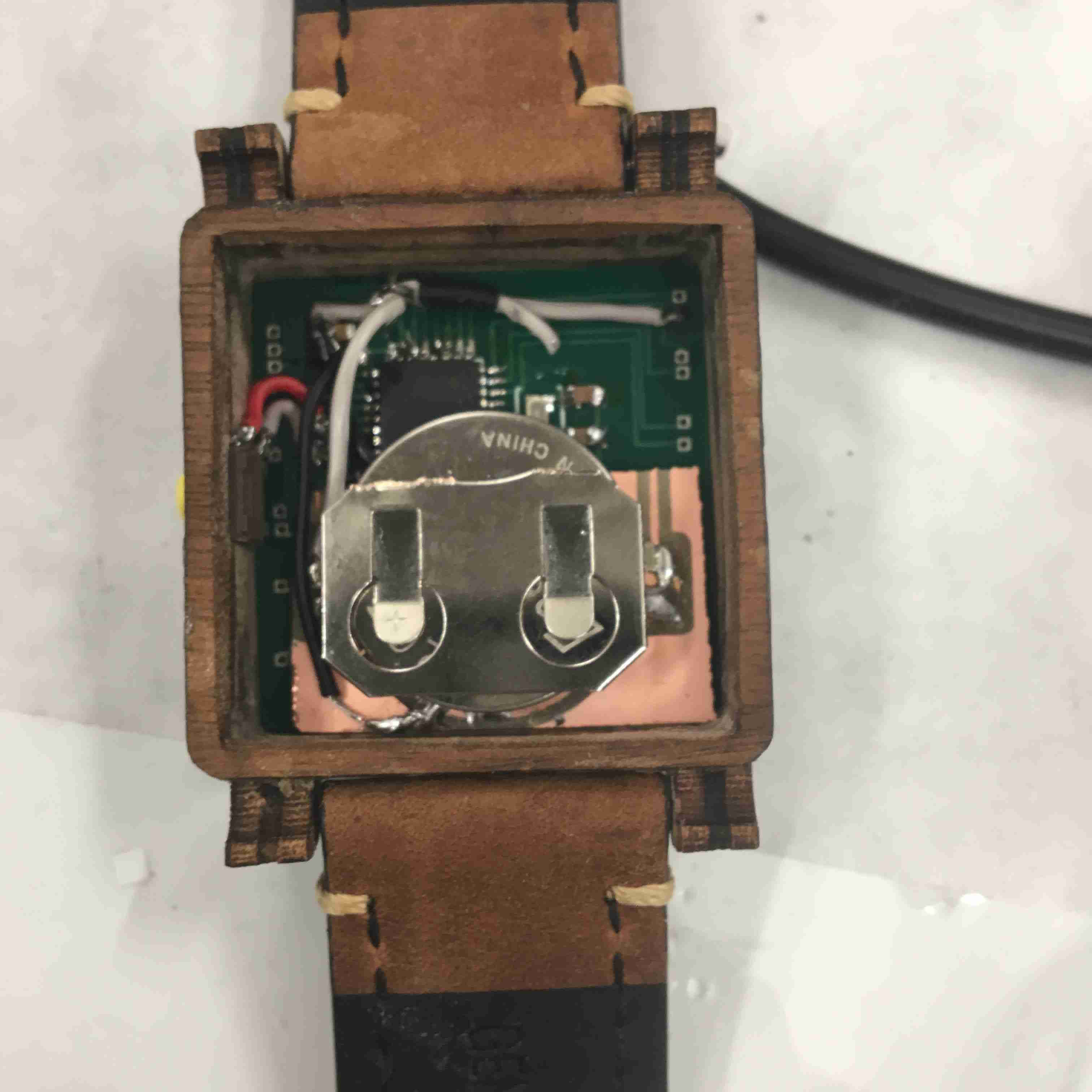
We're good! All nice and pressure fit on the backside.
And we're done. Whew. What a journey. 10/10 would do again. I left out a LOT of the work I did, especially with programming a RESETTIME Function, creating the baffles, and much much more, but this should've been a solid summary.
Questions answered:
Who's done what beforehand?
A lot of people have built wooden word clocks, but no one has built a word watch out of wood. There's a company that does build word watches out of metal, but it's around 800 dollars. I aint got that kind of cash.
Where did your components come from and how much did they cost?
The structural components were just scraps I could scavenge for around Harvard (low budget) and the electrical
components were around 40 dollars, with a 120 dollar PCB (could've been much cheaper, but 80 dollar next-day shipping and I only used 1.5 sqinches out of my alloted 60).
If I were to do it again, it'd be much MUCH cheaper, at around 30 dollars per watch.
Who's done what beforehand?
A lot of people have built wooden word clocks, but no one has built a word watch out of wood. There's a company that does build word watches out of metal, but it's around 800 dollars. I aint got that kind of cash.
Where did your components come from and how much did they cost?
The structural components were just scraps I could scavenge for around Harvard (low budget) and the electrical components were around 40 dollars, with a 120 dollar PCB (could've been much cheaper, but 80 dollar next-day shipping and I only used 1.5 sqinches out of my alloted 60). If I were to do it again, it'd be much MUCH cheaper, at around 30 dollars per watch.