Technologies Used:
❖ RGB Led
❖ Shopbot
Output Devices: RGB LED
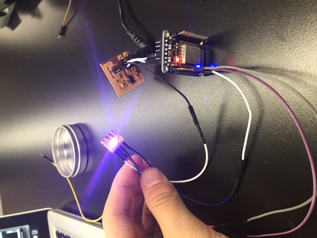
This week for output devices I decided to work on a RGB LED. For my final project, I want my end device to be a small light that changes from data on the cloud, a true IoT device. If you remember from the last section, I almost died getting wireless, and I decided to just chill out, and get an LED working. It actually wasn't as simple as I expected although it wasn't too bad.
The first step for me was understanding how the RGB LED worked. In essence it's 3 LEDs, in each of the colors that share a single Anode. The lighting was then just a combination of RGB "values". Because of the direction of Anode --> cathode, rather than using a pin as a high voltage potential output --> anode --> cathode --> resistor --> ground, RGB LEDs required the Pins to act as the low potential. Thus VCC was connected to the anode, and each LED then "grounded itself" with the pins. The pins would adjust through a mechanism called Pulse Width Modulation, which would simulate a "analog" output on the LED, thus giving the different LED different levels of brightness to create new colors.
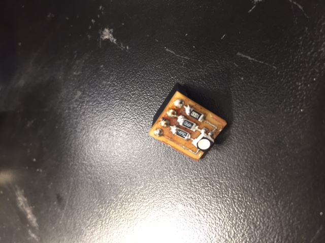
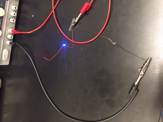
The other issue I had to contend with was I was trying to deal with my LED through a ESP8266 microcontroller rather than a ATTiny or whatnot, meaning the output of my pins was 3.3V rather than 5V, meaning I couldn't simply copy Neil's resistor values when making my board. I thought there might be some nifty math formula to figure this out but I was told by TAs it was actually quite complicated, and would be a trial- and error endeavor. I ended up making a simple circuit and powered it at 3.3V with different resistor values. There's something about the blue LED that needs a lower resistance, so I ended up using 499Ohm for R and G, and 200Ohm for B. I made a small circuit board to test:
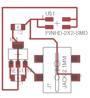
Connecting it to my arduino board was easy enough. I had just created a new board to power my final project through a 2.1mm jack rather than through the FTDI cable, since I wanted to be able to power the module without a computer/USB port nearby. I based the design of this mini board off of Neil's ESP8266 board, it was simply a process of adding the 2.1mm jack and putting in a 3.3V regulator, and outputting the GND and VCC to pins to connect to the rest of my chips.
,
I thought the arduino code would be straightforward to use, and for the most part it was. Rather than use digitalWrite(), in order to power an LED at various brightness one would use the analogWrite() function. However, I couldn't figure out why my code didn't work. I realized that while the documentation states the parameters of analogWrite() go for 0-255 for brightness, for some reason the ESP8266 controller takes values from 0-1024, where 1024 give me no light. After I figured out this piece the rest of my programming was straightforward - just looping the analogWrite() values to get the colors to mix.
,