| Back to Index |
While sitting in class last week, I finally figured out a project that might feasibly bridge the gap between my vision and my skill. I've been thinking about stars a lot lately, and figuring out ways of making an experiential educational thing about the night sky. I was playing around with Chibitronics (LED/resistor stickers and copper tape, an easy way to make LED-centered circuits), when I learned that red LEDs take much less energy to light up than white ones. This makes sense, as red light takes less energy to produce than white light.
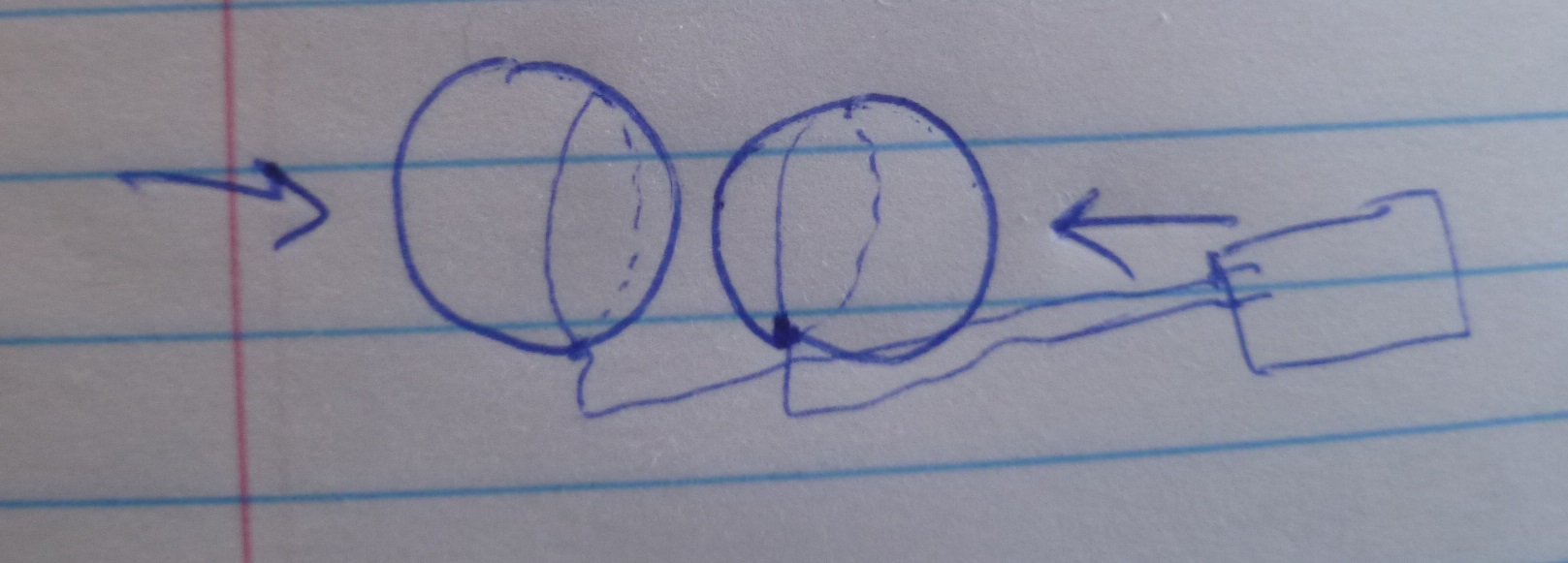
Putting a square of capacitive paper between the battery and the circuit basically means that a light touch will send a litte energy into the circuit, lighting up a Red LED but not a white one. However, add more pressure, and the White LED will light up as well.
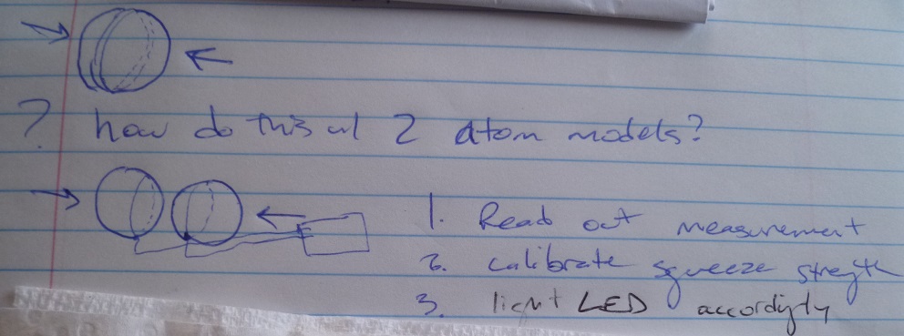
I realized this might be an excellent way to express why different types of stars burn at different colors in an experiential way. Red stars exert relatively little pressure on their cores, where elements are fused. The greater the pressure at the center of the star, the brighter the stars burn.
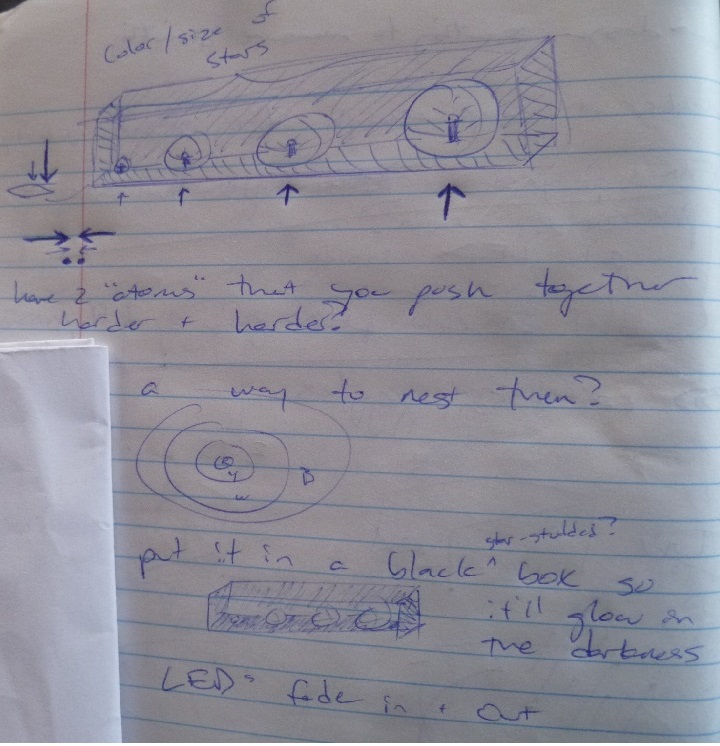
So when Neil started explaining how step-response could be used as a de facto force sensor, I started sketching. By pressing two foam 'atoms' together, each containing one side of the step-response's capacitor, an RGB LED array at the core of a translucently-molded star could change colors from Red, to Yellow, to White, to Blue.
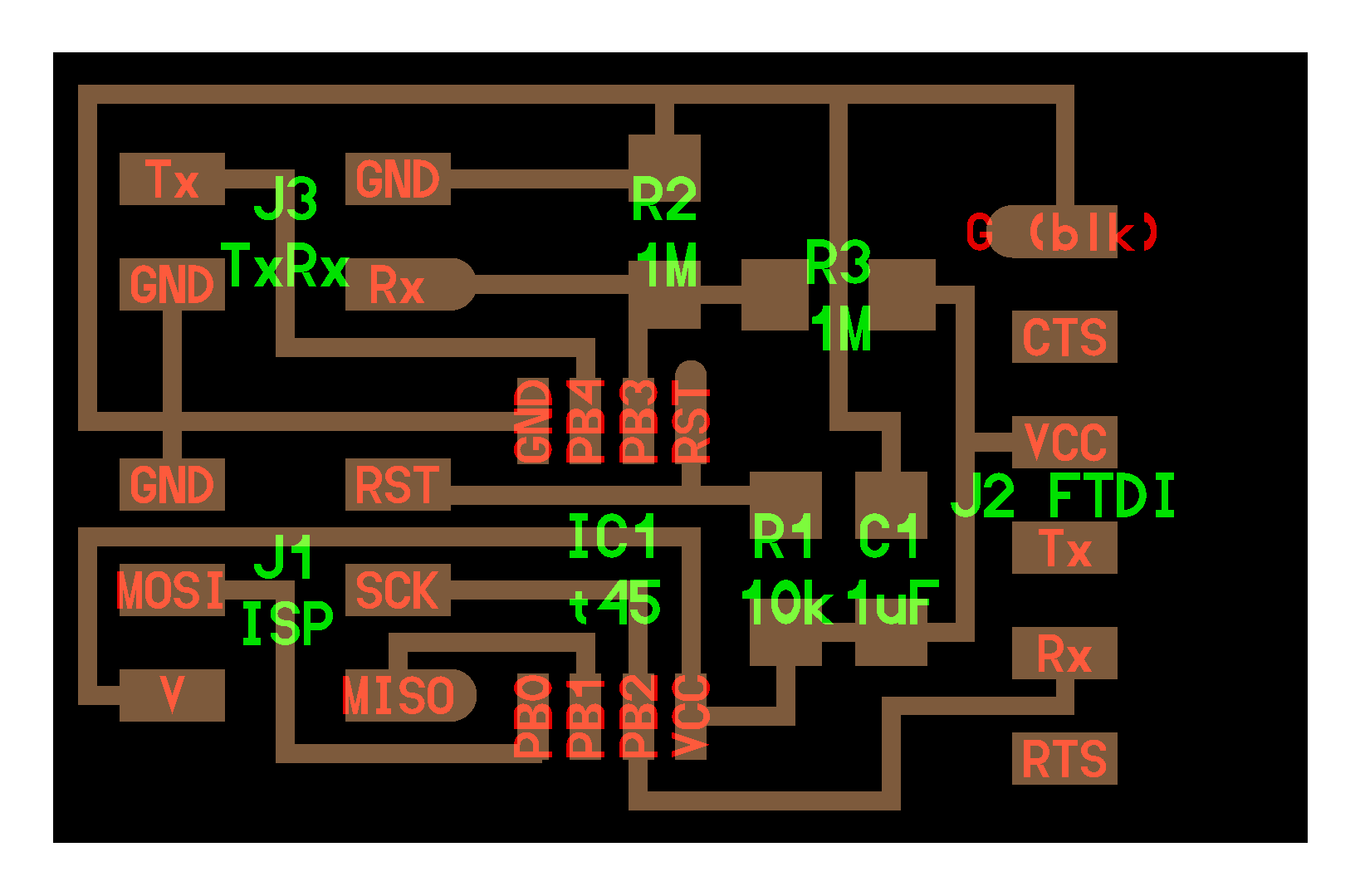
So, with a final goal in mind, I set out to make my step response board. I started with Neil's hello.txrx layout. However, I wanted to add an RGB LED to my board in anticipation of Outputs week. This meant I needed an additional four pins on my microcontroller, and the ATTiny45 that the hello.txrx board was designed (and coded) for wasn't gonna cut it.
Using Eagle -- which was much easier to use the second time around -- I added all the components I'd need (all the ones from the txrx boatd, plus the RGB LED, and corresponding resistors for each LED) to my schematic.
I got a little confused, as on Neil's RGB board (linked to in the Outputs week) connected R, G, and B to the MISO, MOSI, and SCK pins on both the microcontroller and the 2x3-pin header. This made trying to route my new board incredibly difficult, and I wasn't sure why the LEDs needed to be linked to those specific pins. After emailing the Harvard H2M group, my suspicion was confirmed: the LEDs could hook up to any old pin. (I realize now Neil probably routed it this way to efficiently use the T45's limited number of pins)
So, I took a second stab at routing my board. This time, I connected only one net / trace at a time on the schematic, starting with the outermost, most inter-connected traces, Ground and VCC. Once those were laid out, mostly around the perimeter, I was able to start connecting individual components on the schematic, followed by routing the traces on the board. I started to develop some sense of the strategy involved, anticipating what was going to need to connect to what, what was trapping what, and what could pass through what. I left the RGB connections to last, as I realized the pin they connect to would be easiest to determine based on whatever pin was most conveniently located. I only had to use two 0 Ohm resistor jumpers on one trace, which I consider a victory. After a little over an hour, and double-checking everything as I went, I ended up with my board.
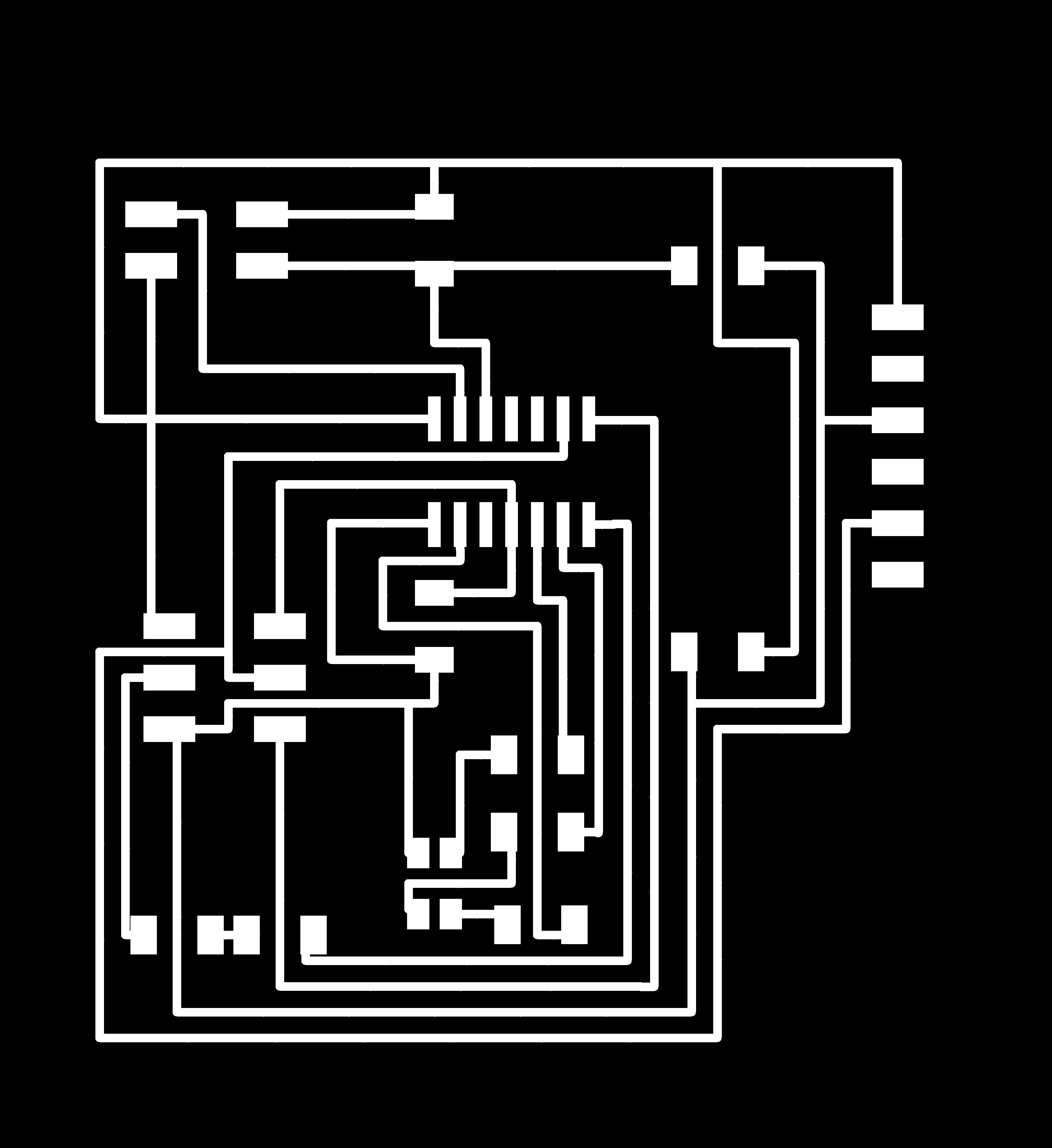
I haven't yet figured out how to label my board's components (e.g. unique resistor values). This would be an issue with larger boards, or collaborative work, but as it is, I knew what went where.
In order to make coding less confusing, I was sure to make note of what components were connecting to which pins:
LEDR ->PA7
LEDB ->PB2
LEDG ->PB0
RST 6-pin -> PB3 (RST)
Tx 4-pin -> PA0
Rx 4-pin -> PA1
MOSI 6-PIN -> PA6 (MOSI)
MISO 6-pin -> PA5 (MISO)
SCK 6-Pin / Rx FTDI > PA4 (USCK)
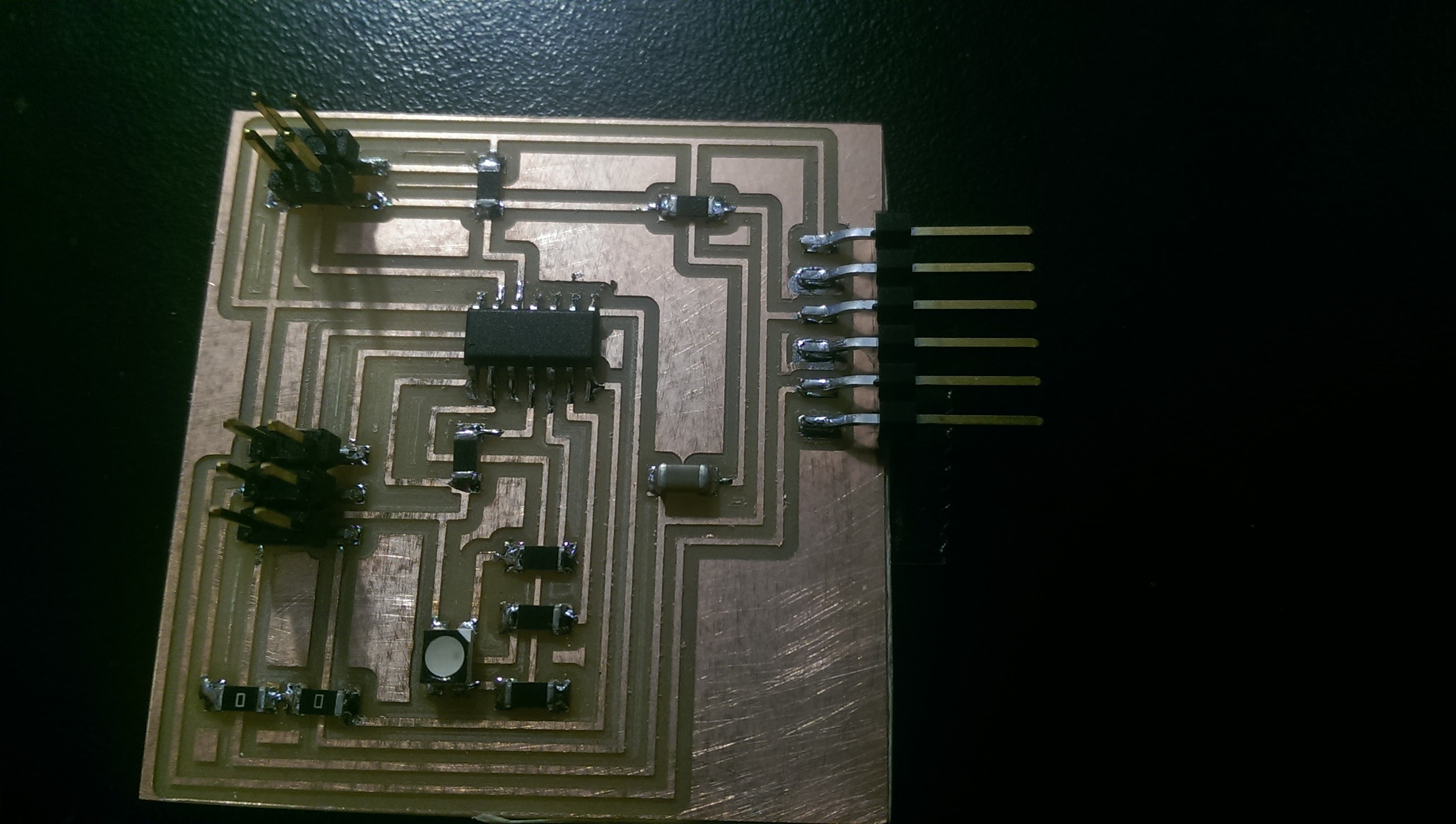
With all the prep work done, I exported the PNG, added a border - making sure to leave enough room to the outside of the FTDI pads for the plastic shroud to support itself - and milled out the board.
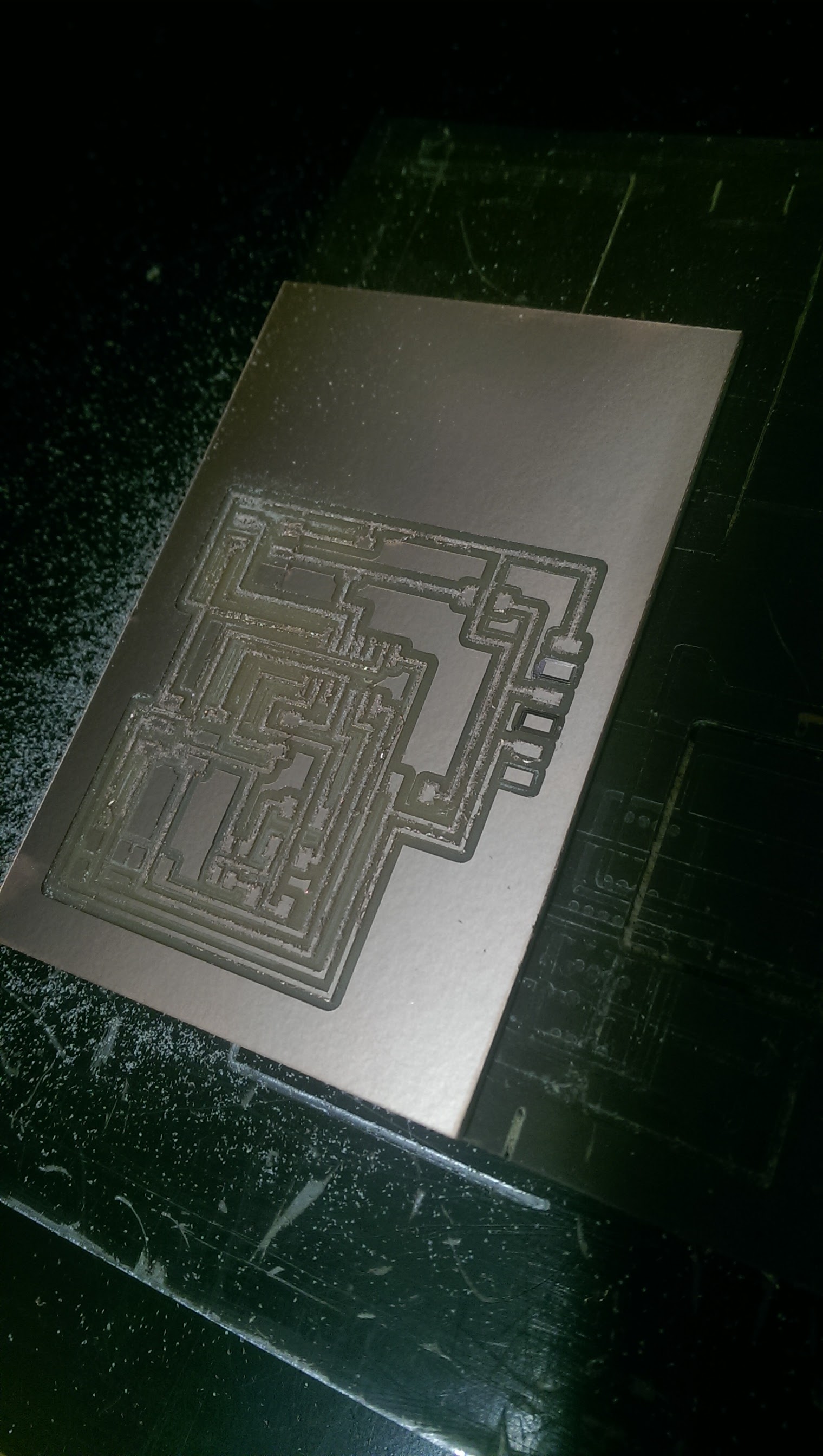
Stuffing was pretty straightforward. The main learning experience this time around was how to use a datasheet to determine which pin on the RGB LED was for power, and which was for each color. I clicked on the RGB link from Outputs week, which took me to the product page. A quick check at the datasheet confirmed that I had, in fact, routed power to the correct pin (phew!), and I saw which pin was for which color - important, as R and G need a different resistor (1k Ohm) than B (499 Ohm).
The thought of coding filled me with dread. I dove into Neil's txrx.c file, knowing I had to not only modify it for my particular pin layout, but also knowing that there were likely differences between the T45 and my T44 which I'd also need to account for. I successfully swapped out the #define serial and #define transmit pins for mine, but wasn't sure how to swap the step response Rx from PB3 to my pin. I knew the following chunk contained the secret, but I was unsure of how to fix it:
ADMUX = (0 << REFS2) | (0 << REFS1) | (0 << REFS0) // Vcc ref | (0 << ADLAR) // right adjust | (0 << MUX3) | (0 << MUX2) | (1 << MUX1) | (1 << MUX0); // PB3
Rob Hart sat down with me and started going over the code with me. Boy am I glad he did! He showed me how to use the T45 and T44 datasheets to determine how to swap from PB3 (Neil's) to PA1 (mine). Example: there is no REFS2 in the T44's ADMUX (Analog-Digital Multiplexer, whatever that means), so we deleted that. We also knew that the two chips required different numbers of bits to identify which pin should be used. The below is where we landed:
ADMUX = (0 << REFS1) | (0 << REFS0) // Vcc ref | (0 << ADLAR) // right adjust | (0 << MUX5) | (0 << MUX4) | (0 << MUX3) | (0 << MUX2) | (0 << MUX1) | (1 << MUX0); // PA1
With the .c (and the make) files updated for my T44, we plugged my board into a programmer. First success: it was recognized! We went to upload the code, and got some error messages.
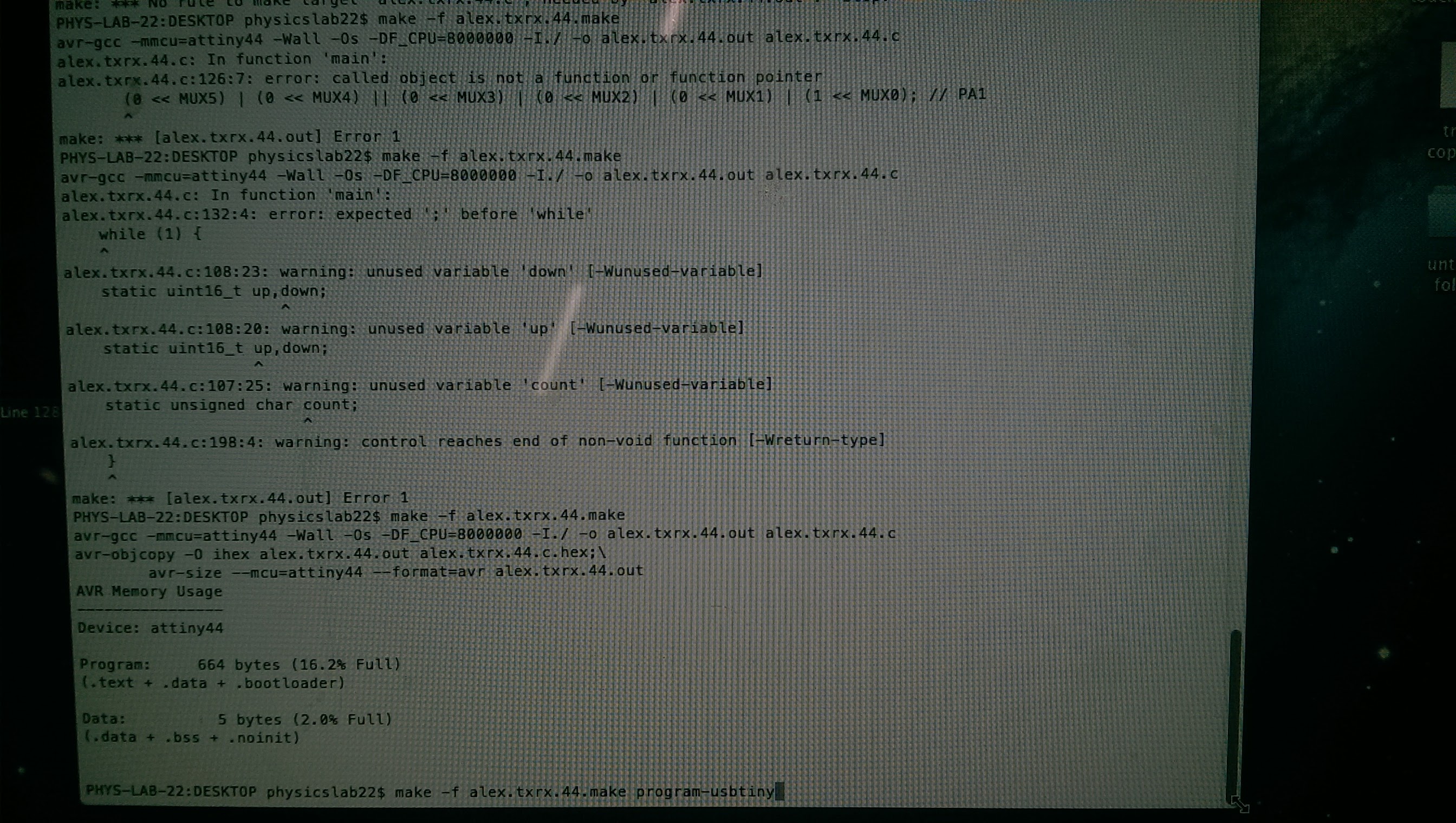
The error messages pointed us to some specific lines of code, which Rob used to help figure out where the issue lay. AT first there were a few typos involving a missing | or a chunk that didn't end in a semicolon. When that didn't fix the issue, we spent some more time examining the code and the datasheets, and figured out that it had something to do with the line ADCSRB = (0 << ADLAR). We though the T44 did have an ADCSRB, but muted the command (with a "//"), and my step-response board programmed successfully.
We plugged it in to his laptop, so we could see what sort of data it was sending out. Using CoolTerm, we were able to see the streaming hexidecimal data it was spitting out. 01 02 03 04 indicating "all is well", then a series of 8 symbols and letters (e.g. CC 09 0F B0) that seemed to change consistently as I changed the proxomity of my copper pads. It was working!
With the week's assignment complete, Rob and I talked through next steps. Basically, I'll need to figure out exactly what kind of numerical data the step response is reporting back to the microcontroller; so I get to learn hexidecimal notation, yay. Using that data, I modify the code so that, when the step response data is between x and y values, the RGB LED glows at z color. The next step (using PWM, I gather) would be to figure out how to get the color to change along a continuum, rathern than abruptly, but that'll go on the "later in spiral development" list.