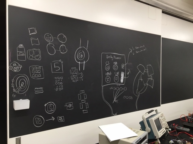
The mess above is the beginnings of the final project ideation. The initial idea was to create small, disposable devices that counted down days and represented numbers with an array of LEDS -- their purpose being keeping track of expiration dates in the fridge. The problem, though, was that there were many inconveniences that made the final product untenable. For example, battery power. Either, the devices would have to be so cheap that they'd be thrown away once dead, or, they'd have to be rechargeable. Rechargeable doesn't work because no one has the time to charge a collection of slightly-useful devices from their refrigerator. I realize that this is supposed to be an exercise in making, not product design, but I'm not interested in making something that no one would even consider buying (not for superficial reasons -- rather because something that no one would buy is probably not a very good idea anyways). Anyways, the idea was discarded, but two elements stuck -- one, circles (I love circles and spheres), and two, representing information with LEDs. Hence the below, an LED-based clock or planner.
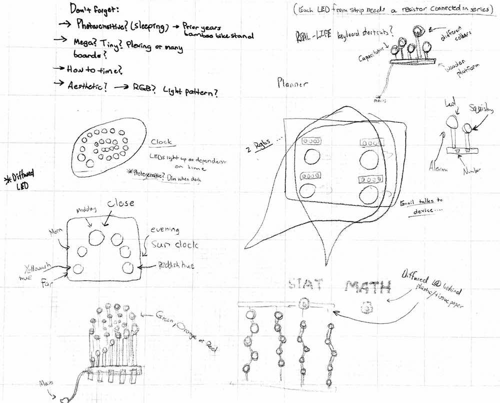
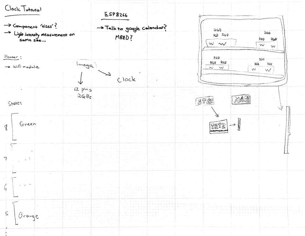
I am currently between two different, but very similar ideas. I'm going to be making a clock, or a planner. Both will represent information with LEDs (behind light-diffusing plastic), and both will have similar physical structure -- wooden rectangle or oval that hangs on a wall. The clock, if chosen, will represent time with 24 LEDs behind a wooden layer (24 circles cut out). The circles will light up as per hour in the day (6am will be represented by 6 circles, 6pm represented by 18 circles). The idea is to represent time in an intuitive, fresh way, and to create something that is aesthetically appealing. A possible modification to the clock would be to use the ESP8266 chip to fetch time from the internet. This would be important for two reasons -- firstly, if the clock fetches time from the internet every two days or so, it will maintain high levels of accuracy (in the event that it slips a second or two behind or ahead, that would disappear with every reset). The second reason, is that the clock will be able to fetch accurate time after being powered down. If the clock is simply a chip that counts hours, then it would lose the time entirely if it is ever disconnected (and would need to be reset manually). If the clock fetches time from the web, it will always boot up with the correct time, irrespective of how long it has been disabled for. Fetching time seems quite doable -- already have three different tutorials saved under bookmarks.
The planner is, at its most basic, a representation of due dates with LEDs and colour. The wooden body would be separated into four different sections, each representing a different subject. The sections will have LEDs that have different states to represent time until a due date. If something is due in 7 days, it may be represented with green circles. Something due tomorrow (or in the next few hours) may be represented with red circles. The idea, is to be able to interact with your schedule without having to interpret a calendar or scheduling app. Simply look at the board, and the colours will tell you what you have to do. In order to set the due date, one would tap a capacitative sensor as many times as there are days before the item is due (e.g. tap 6 times if the item is due in 6 days), and the board would calculate from that point. A possible addition would be to add an ESP8266 chip and fetch data from a google spreadsheet. That way, one would be able to add due dates on the go, simply by dropping an integer into an appropriate cell on the spreadsheet. This (making an avr talk to google sheets) is apparently possible, but only one person on the internet seems to have done it thus far. The downside to this idea is the added complexity. Personally, I'd be much more likely to touch a capacitative sensor a few times... It would take a lot of convincing to get me to drop integers into a google sheet on the go. Technically, an ios app is possible, but then I've just created another scheduling app...
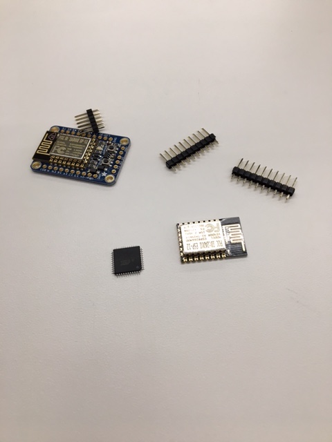
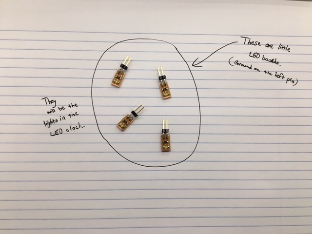
I settled on the clock. Further thinking revealed that, whilst a planner is a 'nice' idea in theory, in practice, I probably wouldn't bother to use it. After a week of novelty, tapping the planner to set the dates would have become one extra chore that I'd be sure to shirk. Clocks are great. You put them on the wall, they tick, job done. This one doesn't tick -- even better! Pictured above are the initial components for the project -- an ATMegaA4U (I grabbed the microcontroller with the most pins -- this one has 34 to programme), an ESP8266 (wifi module) and an Adafruit HUZZAH ESP8266 Breakout (an ESP8266 that has been preattached to the necessary resistors, capacitors, etc. -- doesn't do more, does save time). If all goes well, the ESP8266 will fetch the time from the internet, then pass it to the ATMega. The ATMega will then control the LEDs in the clock accordingly.
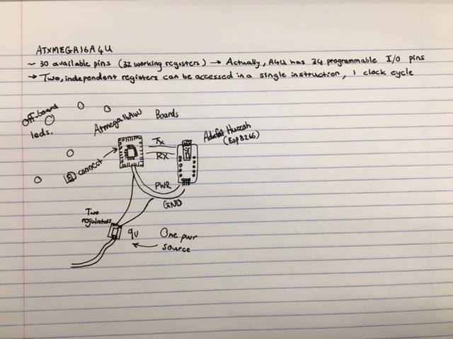
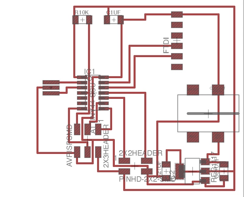
The above is my initial idea for the circuitry in the final project. There will be three primary boards, one with a ATMega, one with the ESP8266, and one with a 9V connector. The 9V connecter board will have two regulators, and will power the other two boards (one may need 5V, while the other may need 3.3V). THe ESP8266 board will serve only as a wifi module, and will be connected to the ATMega board via Tx, Rx, VCC and GND. The ATMega board will contain only the necessary components for the microcontroller, and it will have a host of spaces for wires to connect to the LEDs (or, even better, vinyl-cut copper). There may be small boards with resistors and LEDs built in.
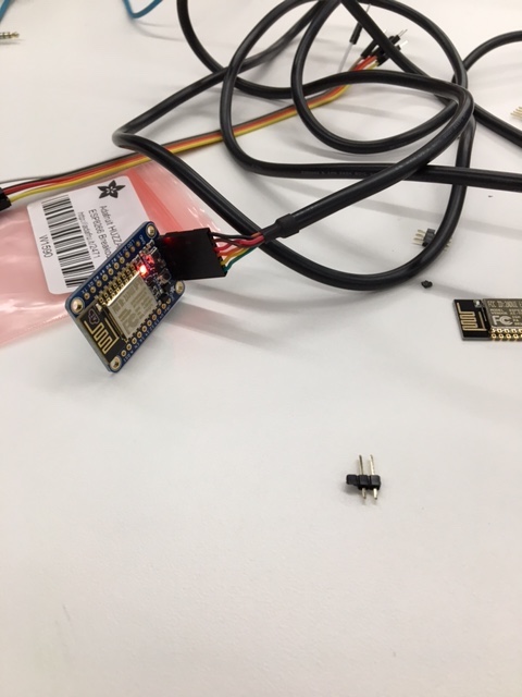
The first step was to connect the Adafruit HUZZAH and figure out what it did. Thankfully, the documentation on the site, linked here, was rigorous, and detailed exactly how to get started with the board. So, after compiling and running a trivial program that blinked the LEDs on the HUZZAH board (picture above), I set out to implement the clock function that I was looking for. Thanks to the firmware that the HUZZAH board ships with, I could jump straight into coding within the arduino IDE (far easier than the AT commands). It is possible to replicate the 'HUZZAH' board by making Neil's 'hello world' ESP8266 board and adding a button for reflashing, but the HUZZAH board saves a lot of time, and minimizes stress. To start the networking process, I found a similar project online, where someone had programmed an ESP8266 to get the time from an online server. You can find this project at this page. While the code did not do exactly what I needed it to do, it provided the details that most concerned me (how to connect to a host, and how to query that host). After some searching online, and some fiddling, I edited the code for my needs, linked here: code This code now queries a server for UTC time, returning a string with the time and date. A substring is taken out of that string, in order to capture only the hour. Then, the substring is typecast into an int (toInt()), and that int is encoded into a character (A through Z, where A is 00 and U is 20). That character is then sent out via serial (Serial.println()), where it can be read by a computer, or another microcontroller. Figuring out the ESP8266 code was somewhat easy -- it only took 4-5hrs -- almost certainly because of the streamlined arduino IDE and HUZZAH board. If you've worked with the arduino IDE before (I hadn't), then it'll be even faster.
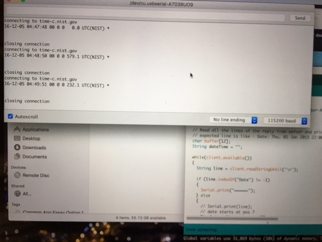
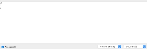
Pictured above: On the left is a picture of the output that the code I found online provided (after I changed the server). On the right is the output after my changes (I scrapped all of the readable text for ease of communication between microcontrollers, changed the server queried, typecast the output as described earlier, and fiddled with the delays to allow for (hopefully) fewer errors). The 'U' represents 20, and was printed because, at the time, it was 8pm UTC. The '28' is my encoding for 'no connection', and it was printed before the ESP8266 connected to my mobile hotspot.
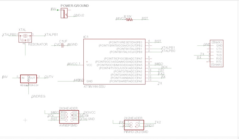
Before even starting to consider the networking code (connecting a tiny and ESP8266 via serial), it's necessary to have a board that connects them electrically. In order for them to communicate, Tx, Rx and Ground must be connected -- Tx and Rx for obvious reasons, and Ground because the microcontrollers need to have a common reference point. I chose to connect my VCC too, as I want my final project to be powered by a single 9V plug. I designed a simple board to achieve those aims. It had a tiny44, a clock, a host of pins for various connections (FTDI for computer communication -- no VCC connected, 2x2 header for ESP8266 communication, 2x3 header for programming), a barrel-connector for the 9V plug, and a regulator to regulate the voltage down to 3.3V. The schematic is below.
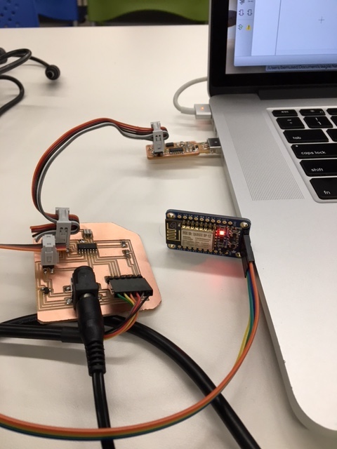
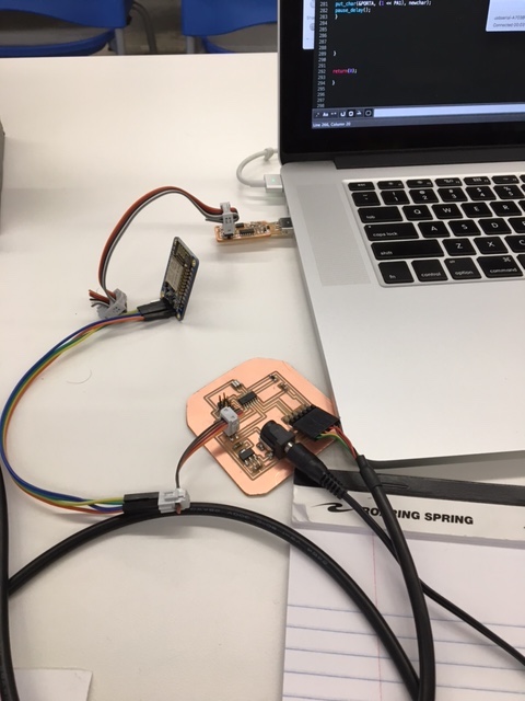
After fabricating the board, I reprogrammed the ESP8266 with a simple code that blinks the LED (easier to check electrical connection) and connected the boards. Everything seemed to be working smoothly, as the ESP8266 was being powered by the tiny44 board (pictured below).
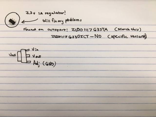
Satisfied with my blinking LED, I reprogrammed the ESP8266 with the 'clock' code, and connected the boards again. This time, it didn't work (I noticed, as my iPhone was registering no connections to its mobile hotspot). This was due to my choice of regulator. As the Adafruit website documents clearly, the ESP8266 can draw as much as 250mA when connected to the internet, and my 3.3V regulator had a paltry max of 100mA (problem documented at the bottom of the picture below).
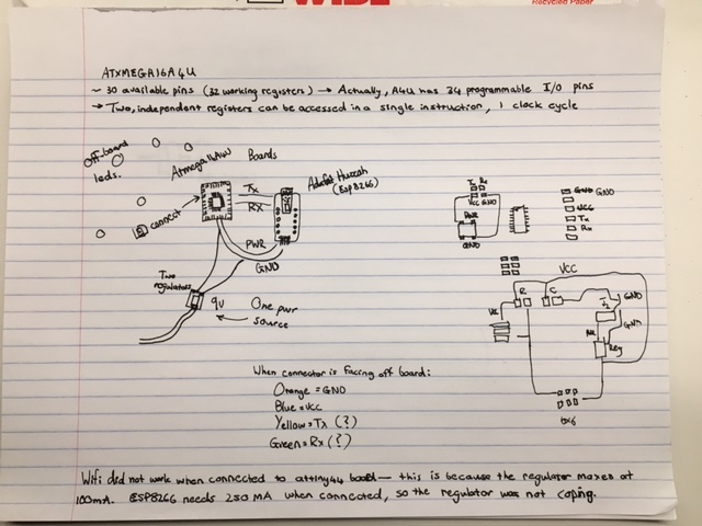
Thankfully, the solution was very simple: replace the regulator.
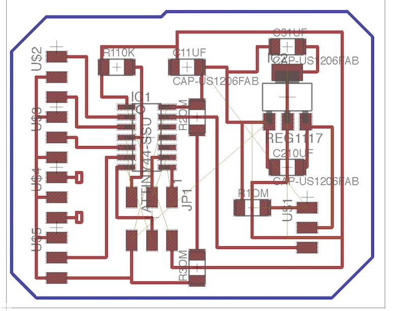
So, I edited my tiny44 board, fabricated it, and connected it to the ESP8266. Everything was electrically connected. The traces for the final tiny44 board, and a picture of the tiny44 connected to the ESP8266 are below.
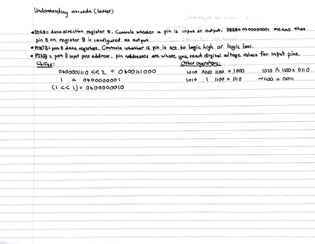
Having electrically connected the two boards, the next step was to make them actually talk to each other. At the time, the ESP8266 was outputting the encoded time via serial, so I had to make the tiny44 listen. Here comes the biggest learning thus far: when trying to code for the microcontrollers, there's no substitute for a solid understanding. I hit a wall when trying to design the serial communications code -- 2-3hrs of frantic googling and playing with Neil's code yielded nothing. Eventually, I decided to quit while I was behind, and settle down with the 'Make: AVR Programming' textbook. After three hours of reading (and some more pointed googling), I understood what the code was doing. Whilst I 150% recommend reading the book, if you *must* have a summary, I've included one below. Here are the most important details:
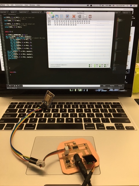
With my new understanding, I set out to write the code. After 4hrs of coding and debugging (I mixed up Tx and Rx a few times), it worked. Finally. The code I wrote is linked here. This code has a few main components. I borrowed the get_char and put_char functions from Neil's code (can be found in many of his serial communications pieces), as they efficiently receive incoming bytes from serial, and send new bytes into serial. get_char is used to fetch the time from the ESP8266, while put_char is used to send the time out via serial (currently sent to my computer, will later be sent to an ATMega). The cambridgetime function receives an incoming char from the ESP8266 and converts it, converting UTC time to the time in cambridge. Then, the main function simply initializes the input and output pins, then checks for incoming info, and, if it finds that the ESP8266 is talking, it prints '1 2 3 4', followed by the time (printed three times). Because I'm lazy (or efficient, depending on your perspective), I downloaded one of Neil's makefiles and renamed my code to match, so I didn't have to make my own makefile. One note: if you do this, make sure that you download a makefile intended for the chip you're trying to programme. Using a makefile intended for an attiny45, for example, will throw errors when used on a file intended for an attiny44 (because the attiny45 doesn't have an 'A' port, so any reference to 'DDRA', 'PORTA' or 'PINA' will be undefined). The picture below is of the beautiful moment where the communication worked for the first time.
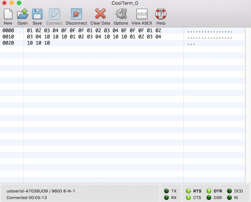
And here's a closeup printout of the output (in hex). The '0F' is hex for 15, telling us that it's 3 o'clock. The '10' is hex for 16, telling us that it's 4 o'clock. The '01 02 03 04' is hex for '1 2 3 4', and is printed between prints of the time, as coded.
At this point, I have a functional clock that pulls the time from the internet. Now, to sort out the LEDs...
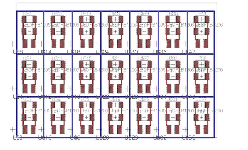
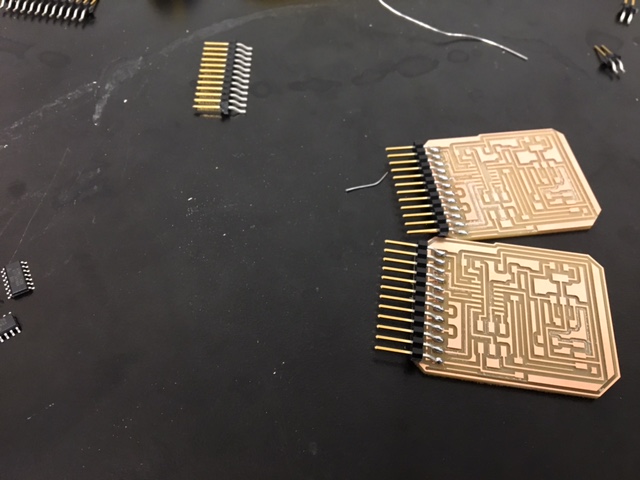
I couldn't put the LEDs on the main circuit boards, because the clock design required that LEDs could be spaced further apart. Therefore, I designed a tiny 'satellite board' that holds only the LED, a 1k resistor (seems to be the optimal amount for brightness and minimizing excessive current), and two header pins for connecting. Pictured below is the array that I designed. I did start out by cutting one LED board at a time, and, despite each board taking less than a minute, the process was lengthy and incredibly tedious (because the ShopBot had to be zeroed between every board). Thus, I made the array -- such that I could zero once, press 'start', and work on something else. Just a note -- perhaps consider finding some alternate way to attach the copper board to the sacrificial layer, if attempting this design. Double-sided tape failed twice. Because the board was split into so many small individual pieces, there was no remaining piece with significant surface area, and so the adhesion would fail during the cut. I didn't find a solution to this problem -- I just salvaged the usable satellite boards from the failed cuts, until I had enough.
To clarify, at this point I had: an ESP8266 configured to fetch time from the internet, a tiny44 motherboard that received the time and converted it into cambridge time before sending it out through serial, and 24 satellite boards with LEDs on them. The next step, then, was to design the board that connects the tiny44 motherboard to all of the LED satellites (the board that receives the time from the tiny44 motherboard). I had a choice to make -- design one complex board, using the ATxMega16A4U (32 pins, so could handle all of the LEDs), or design 4 relatively simpler boards with tiny44s on them (with 6 free pins, they'd split the task). I weighed up the options, and eventually settled on 4 tiny44 boards. This is partially because the ATxMega16A4U has to be programmed and configured differently (so I'd have to spend a lot of time figuring out the new chip) and overwhelmingly because Eagle does not have the schematic for the ATxMega16A4U preinstalled, and I did not want to have to figure out how to add new components to Eagle. Eagle is the worst, so time spent with the software must be minimized.
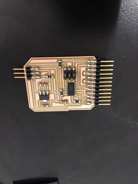
The above is the board that I designed to act as the intermediary between the motherboard and the LED satellites. The board is very straightforward. It has a 2x3 header for programming, a tiny44 as the microcontroller, a 3.3v regulator for regulating the bussed 9v (and the two requisite capacitors to reduce noise), a 3-pin header for receiving ground, vcc and Rx from the motherboard, and a 12-pin header for connecting ground and vcc to 6 satellite boards. You may notice that two pins on the 12-pin header don't connect to the tiny44. This was designed to be corrected during post-processing with jumper wires -- routing the pins seemed like more effort than it was worth. Once milled, the board looked like this:
And, once stuffed, the board looked like this (sans jumper wires):
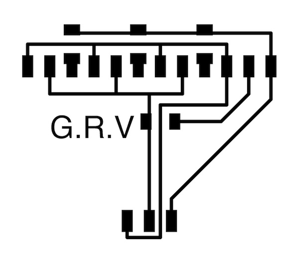
The last hardware 'problem' to address was that of connecting ground, vcc and a single Rx line to four separate boards. My solution was to design an 'adapter' board. The board doesn't actually 'do' anything -- it simply has a 3-pin header for vcc, ground and Rx input that then splits into 12-pins, partitioning each input into 4 outputs. There are some 0ohm resistors used as jumpers. The 'G.R.V' printed on the board represents 'ground, Rx, vcc', to remind me of the ordering when wiring (the order isn't defined by the board, but the convention allows for efficiency later on).
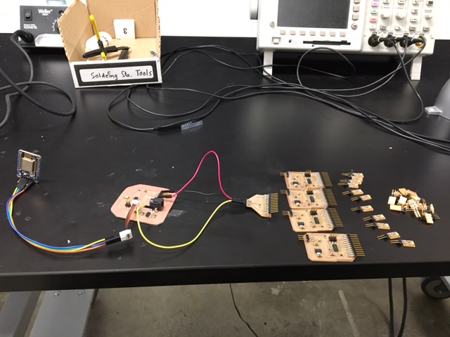
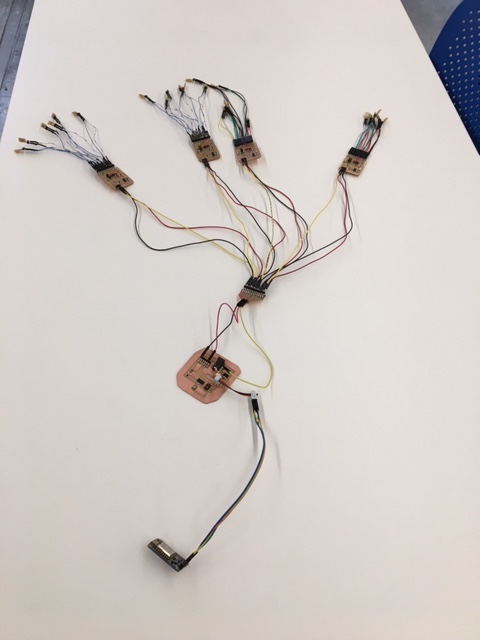
After 4-5hrs of milling and stuffing boards, I had successfully fabricated all of the electrical hardware required for the project. The logical ordering of the various boards is pictured below:
Before developing the software for the four intermediary boards, I decided to address connecting the boards together, as I was concerned that we lacked female connecter wires in the lab. I was, unfortunately, correct. I'm not going to complain too much... But I spent 3hrs crimping wires. It was sheer torture. There's no fast way to complete that obnoxiously fiddly, mundane task. It will take long, and it will be terrible. /rant. That does lead to one of the most obvious (but meaningful) learnings of the class -- there's no way to fast-track making. Making takes long. It's a fact. Sometimes it can be relaxing to spend 3hrs soldering components onto boards, or milling components, but making is not something to leave till the last minute -- failure to begin timeously will result in failure overall. Anyways, I digressed -- software... The code for these boards was quite simple. To understand it, here's a reminder of what it needed to do:
My ESP8266 module was fetching the time from an online server, encoding it into a character and sending it to my tiny44 motherboard via serial. The tiny44 motherboard was decoding the character and converting it into Cambridge time, then sending it out via serial. Therefore, the four intermediary boards had to listen to the motherboard's Rx line, accept the incoming integer, and determine what LEDs to switch on. Here's the code for the four boards: board 1 board 2 board 3 board 4 And here is the makefile for one of the boards (it applies to all of them, after a title change): makefile
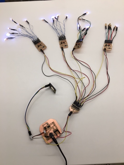
In order to manage 24 LEDs, I split the 24 satellite boards between the 4 intermediary boards, with board1 handling the first 6, board2 handling the second 6, etc. I set up a convention across the four boards, such that each board had the same ordering for LEDs 1 through 6 (i.e. PA3 is LED 2 on all four boards) -- this made for easier copy/pasting between the four boards' code. The code uses Neil's get_char function to receive the incoming time via serial. Within the main function, the input and output pins are initialized, and then there is a simple set of if/else statements to determines which pins to set high/low, depending on the incoming int. The only meaningful difference between the four boards' code is in the if/else statements -- though even those are very similar. Most notably, board4 always has its last pin high (as I want the center light in my clock to be illuminated at all times), and, while board1 must have all pins high for any number above 6, board4 must have all pins (except for the last) low for any number below 18. Once I successfully programmed the four boards, I had completed the electronics for the final project. Completed electronics pictured below :D :
There was only one significant bug in this very simple code. Initially, I had programmed the boards to flicker their lights when there was no internet connection. The first iteration of the flickering was too fast -- not a bug, but it almost made me sick. The second iteration of the flickering, while at a reasonable speed, had its own problems (though, I'm convinced that this problem would have been true of the very fast flickering too -- I just didn't leave it for long enough to find out); when in the 'flickering state', the boards refused to enter a new state. This meant that, once the boards started flickering, they had to be reset entirely in order to display the time again. Instead of debugging that problem, I decided to change how 'no internet connection' was represented -- eschewing the buggy flickering in favour of a simple LED arrangement that would not be possible through normal time functions. This worked perfectly, and I figured that flickering lights would be more irritating for a user anyways. However, I did put some thought into into the flickering bug (and the code is still in the c files -- just commented out), and I think that the problem is due to the rapid adjustments made to the voltage supplied to the input pin. I suspect that the boards were unable to listen for a new incoming integer once they started flickering, so they continued to operate off of their 'no connection' integer (28) indefinitely. One last change -- worth mentioning: I removed the signal integers ('1 2 3 4') from the motherboard's output code. After thinking about it more, I realized that the signal integers were unecessary -- after all, there is no stream of data that needs to be read, only a single integer being output repeatedly. In the event that the integer is missed, it'd just be read the next time. This is why there is no code to read the signal integers in the intermediary boards' code.
With all of the software and hardware completed, it was time to design and fabricate the body of the clock.
I made two purchases for this project -- a 24x30, 3/4 thick* sheet of wood, and a small roll of light diffusing plastic. The light diffusing plastic was purchased from inventables.com, while the sheet of wood was purchased from the wood store in Porter square. At $20 each, the entire project costs amounted to $40, not bad. *important note -- I'm not using the measurement in inches because they're reasonable quantifiers of length, but rather because I'm too lazy convert. Inches and feet are ridiculous, and it's about time that America adopted the SI units. Hell, to spite this absurd system -- my wood was 762mmX610mm, 19.02mm thick.
The plan was to design the clock body in Fusion 360, then mill it on a large ShopBot (using PartWorks 3D to prepare my file). So, I got to work designing the body.
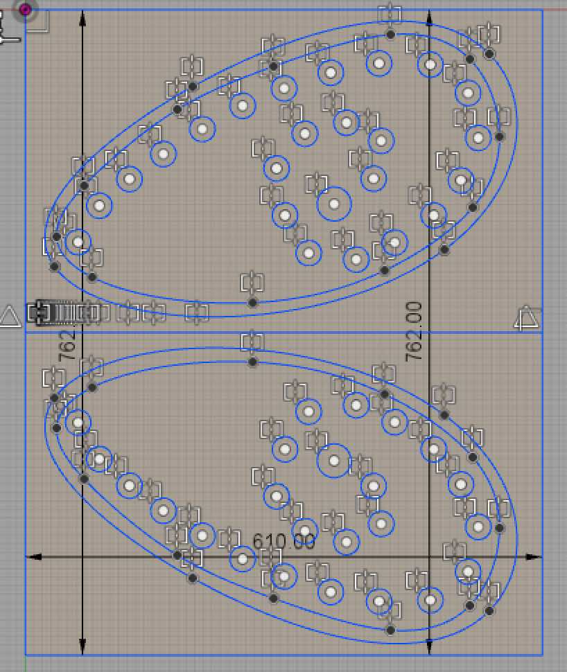
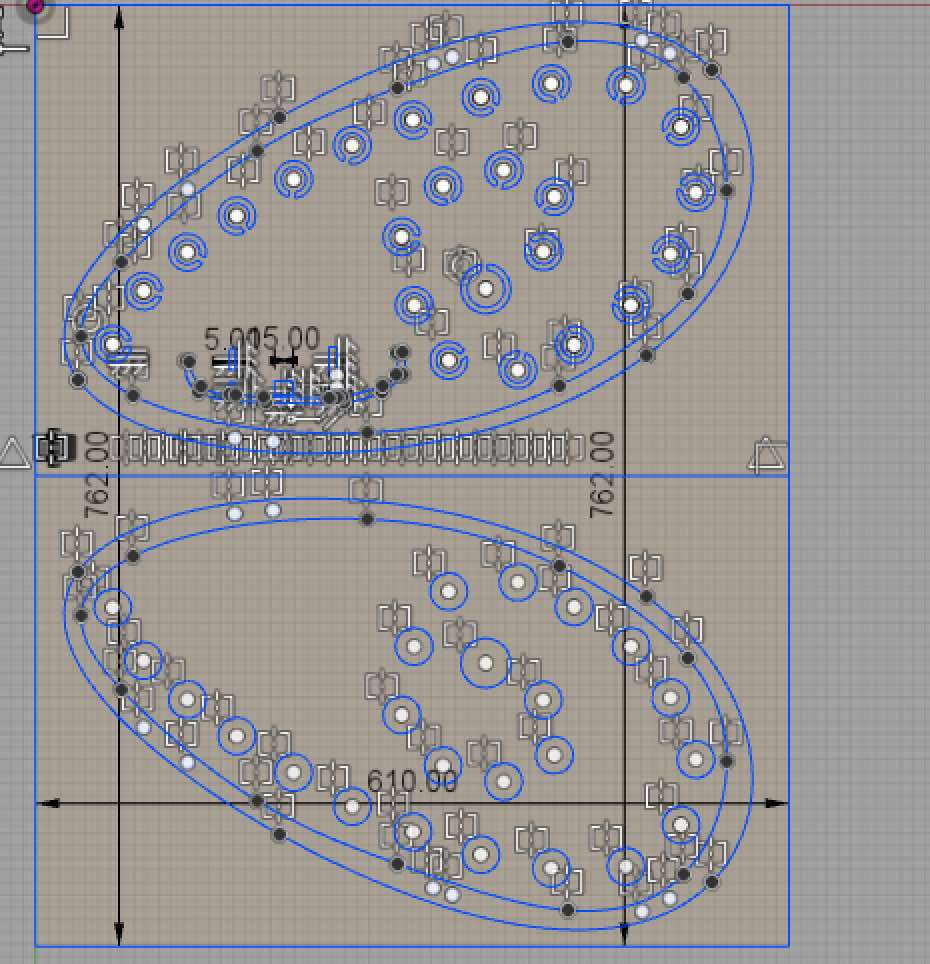
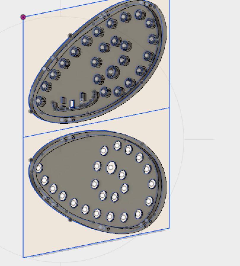
The shape of the body was entirely based on my initial drawing, pictured near the top of this page. The significant design decisions that had to be made pertained to organizing the electrical components within the shell. I chose to create a small, circular compartment for each satellite board, in order to prevent light from dispersing within the shell, and hopefully focus the light from each satellite board into the correct area. Milling the design proved to be far more difficult than initially imagined...
While I had originally planned to export my 3D .stl file and mill a 3D piece, Rob advised strongly against that idea. His reasoning was that the method of cutting would provide a much more jagged finish, and that it would take far longer. Eventually, convinced by his reasoning, I closed PartWorks 3D (where my .stl file had imported so easily) and opened Vcarve Pro. This was possible, as my piece wasn't particularly '3D'. As Rob said, it was '2.5D' -- it could be completed with a few 2D cuts at different depths. However... exporting my .dxf files from Fusion 360 to Vcarve Pro was a nightmare! The reason, as I eventually discovered, was due to the splines. Despite what Fusion 360 says about splines exporting 'easily' on their website, they don't, at all... The splines that I used to form the curves on my piece made it impossible for me to get my .dxf files into Vcarve, or even CorelDraw. Eventually, remembering my experiences in the 'make something big' week, I attempted to export my .dxf files to Rhino. Rhino complained, but it opened the files successfully. In Rhino, I ran 'Make2D' on my piece, then deleted any stray open vectors and ran 'Join' to patch any holes. Once satisfied, I exported, and opened the files in Vcarve Pro. Success! Finally. But then disaster struck...
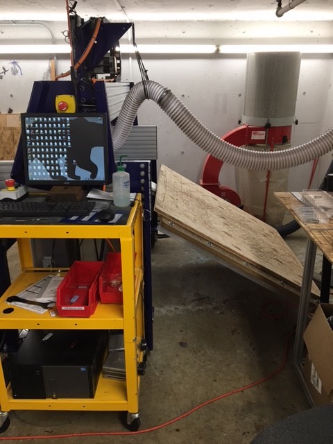
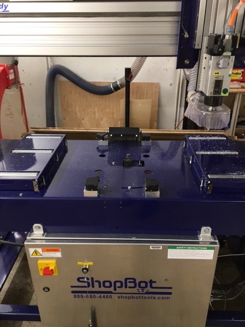
No, your eyes do not deceive you. Pictured above is a broken ShopBot... Just great. I don't know how it happened (and thankfully, Rob, who was there too, doesn't either). Rob was helping me set up the machine -- changing the bit, zeroing, etc. I used the arrow keys in the ShopBot software to move the machine head, then it froze. Befuddled, I asked Rob to take a look. The ShopBot refused to budge, so we switched the machine off, then switched it on and pressed the reset button (as the machine requested). As Rob pressed the 'right' key to move the head right, the machine made whirring noise, and shot its entire machining bed off to the right.
With the large ShopBot out of commission, I thought I was a goner -- until Rob made his second brilliant suggestion. If I were to cut my wood exactly in half, it would fit onto the smaller ShopBot upstairs, so I could still finish my project. Rob then helped me to cut the wood in half with a bandsaw, and I was off to edit my .dxfs and ShopBot files for the new cuts. Before I move on -- one important tip for setting up the .sbp files -- use a larger bit when pocketing. Carving out the inside of my clock shell (pocketing) was the process that threatened to take the longest -- with initial estimates at roughly 13hrs (!!!!!!!!). However, after selecting to use a half-inch bit for the initial pocketing, reducing the number of passes and increasing the feed rate, I had that down to 24mins.
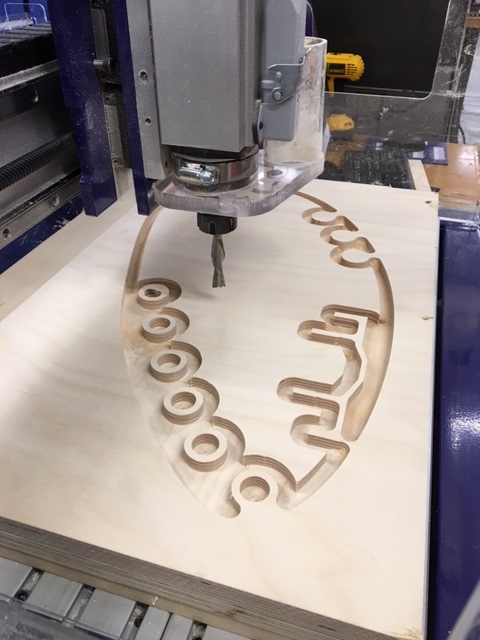
Milling such a large amount of wood with such a big bit was incredibly noisy, and even sounded dangerous at times. I did have to reduce my initial feed rate (3 inches/sec) down to 2 inches/sec in order to make it a little more manageable, but that didn't stop us (me, and anyone else in the lab at the time) from cowering in fear in the corner of the room. However, after much ado, the milling was complete. I'm skipping a bunch of time-consuming but boring details... They include: losing the necessary bits, not having a collet (and begging a security guard to let me into the downstairs lab after hours to fetch one), fixing my files over and over again on Rhino, exporting the wrong thing repeatedly, pausing the machine because we thought that everyone was going to die, etc...
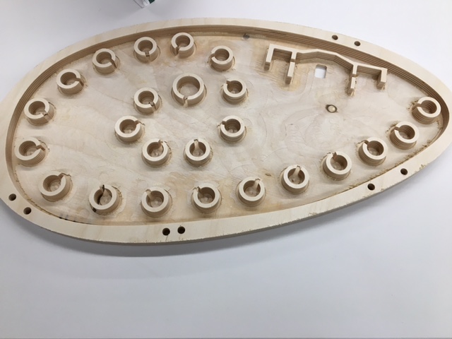
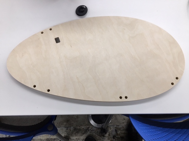
The above is the bottom of the clock. I thought that it came out pretty well. You can see the separate compartments for the satellite boards, the scaffolding for the other boards, and the hole for the power cable. While the top part of the clock was milling, I got to work on stuffing the base. Fitting the circuit boards into the body was less trivial than I had imagined -- the mess of wires quickly became very intimidating, and nothing that I stuck down would stay stuck. I eventually got it to work, though (a theme of this class), thanks to a roll of double-sided tape and two more hours of crimping wires (I swear, if I ever have to crimp a wire again...).
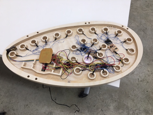
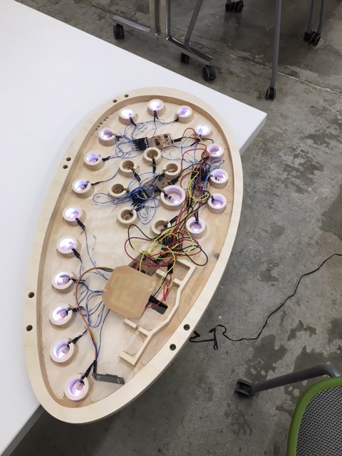
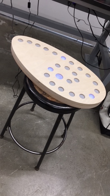
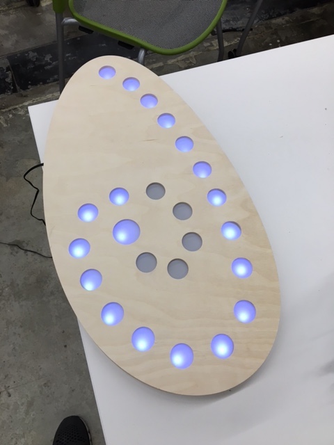
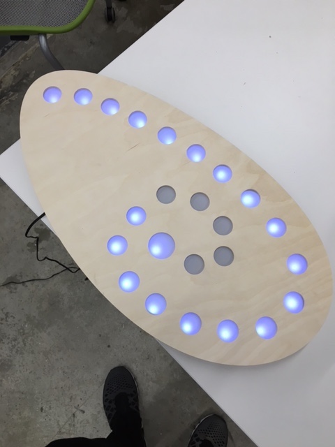
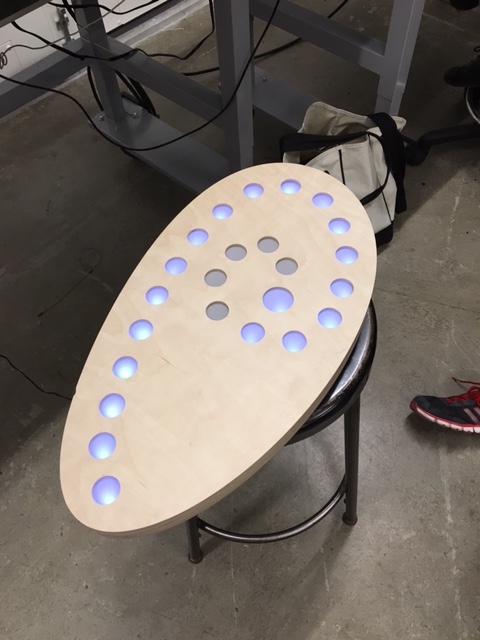
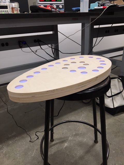
With all of that done, I stuck the light-diffusing plastic to the underside of the clock top and assembled the final project. The first image shows the light arrangement for 'no connection'. The rest are showing 6pm (18 lights lit up, with the center always illuminated)
And there you have it; a LED clock that fetches time from the internet. Phew, what a journey. This project probably took 30-40hrs -- not necessarily because it was all super difficult, but more because there was a lot to learn, and everything tends to go wrong when making things. Also, as I mentioned earlier -- there is no way to fast-track making -- it just can't be done. This project involved skills from multiple weeks -- week 1 (CAD), week 3 (PCBs), week 5 (electronics design), week 6 (CNC), week 7 (embedded programming), week 9 (input), week 11 (output) and week 13 (networking). Perhaps the greatest part of this whole process -- I could do none of this prior to the class. I had never used any CAD software (besides Gimp for a week), I had never done anything with circuitry (besides some simple V = IR calculations in highschool physics) and I had certainly never milled anything. It surprised me -- I hadn't fully comprehended just how much I'd learned. Thanks HTM[a]A -- it's been swell!