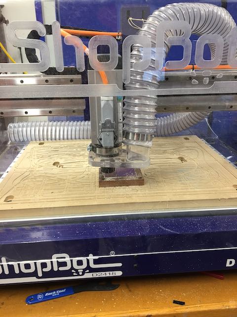
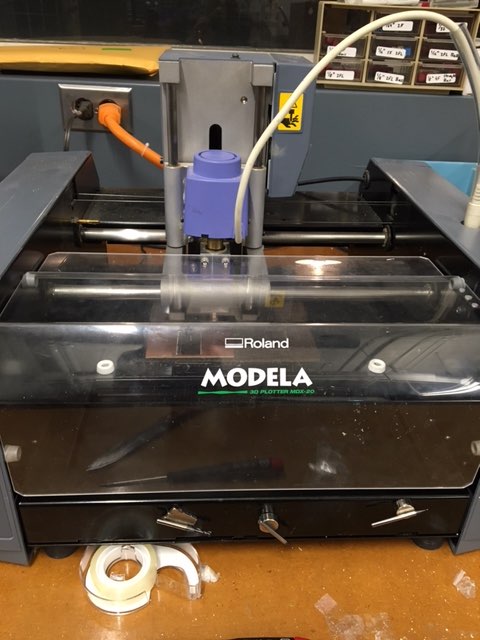
Initial observation: this process is incredibly finicky. Milling the pcb could, and should, have been somewhat uneventful, but, it turns out that every advised setting is advised for a reason. I was unable to access the Roland mill for my pcb, so I used the ShopBot (pictured below) instead. The ShopBot was way faster (and apparently more precise?), but the speed came at a cost. I forgot to adjust the speed settings, so the process ran at the default speed of 20. By the time the milling had finished, the 1/64 endmill had been ground away, scattered amongst the pcb flecks littering the machine. Yes, I confess, I was the first to break an endmill in the Harvard section. Note for all future mill-ers -- run the ShopBot at a speed setting of 5. The interesting outcome, however, is that the board was still cut out somewhat correctly. This is perhaps due to the fact that the remains of the endmill was still actually quite sharp. There were two noticeable errors, but only in areas that weren't necessary for the board to function (talk about luck).
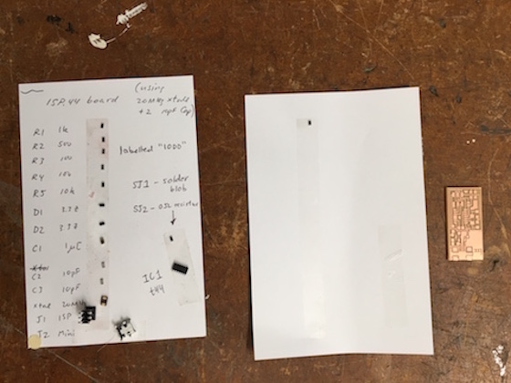
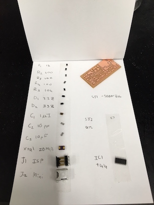
Once the pcb had been milled, it was time to collect the components. As a beginner, collecting the components is a thoroughly mysterious process. What is a 'capacitor'? What does it do? More importantly, what does it look like?? Huge thanks to whoever labelled everything. I can completely see the necessity for good lab etiquette -- if someone were to replace things in the wrong tubs, I'd be furious. It is also very necessary to devise a clever labelling system for the components once collected. The parts are far too small to label individually, and they'd certainly get lost if not contained in some way. The solution that I used (not my idea, though) was to write out all of the labels on a sheet of paper, and attach the respective components next to the labels with double-sided tape. Below, you can see the 'example sheet', next to my own.
They say that soldering is relaxing, like therapy almost. They must be good at soldering... A few notes: 1. Solder blobs are easily removed with copper braid. The shiny layer of solder that attaches to the copper lining will NEVER be removed. Stop trying. 2. Copper braid is a fantastic conductor of heat, hence its use. Copper braid will burn your fingers. 3. The diodes have an orientation. Most diagrams will show the diodes with a line on a certain side. This line is also present on the diode. Line them up. 4. Chips also have orientation -- line up the dot on the chip with the dot on the diagram. 5. If four of the legs of your chip are all connecting to ground, the board didn't cut out correctly. Redo it. By far, I found that the easiest way to place components was the following: 1. place solder blobs on all areas that will later have components. 2. hold component over solder blobs with tweezers, gently press the component into the blob. 3. heat one of the blobs while holding the component in place with tweezers, it will attach once the heat is removed. 4. stop holding the component with tweezers, it would have attached to the solder blob. 5. heat the solder blob on the other side, gently press the component into it with tweezers. I don't trust the heat gun enough. I realize that it's manufactured to remove components from a board, but the one time I saw it used, it melted the board. I much prefer heating one side of the component with the soldering iron and then ripping it off with tweezers. The component is sometimes broken in the process, but the board stays intact, and the component can be easily replaced.
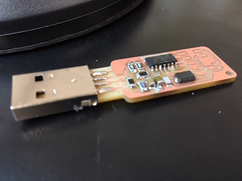
Above is my first board. It didn't work, at all. When connected to the computer for programming, the computer failed to detect its existence. I attempted some basic board debugging (checked that power was running to all of the components), and, upon discovering that there was no obvious issue, elected to make a new board instead of finding the non-obvious issue. The second board-making went smoothly, until it was time to program. This board was detected by the computer and programmed smoothly! Victory! .. or not? Board #2 refused to act as a programmer -- attempting to program another board threw errors that I didn't understand (rc-1, if that means anything to anyone). The dilligent, studious version of myself would have skimmed the c code to attempt to understand and debug. The studious version of myself was not present at 11pm. I went home.
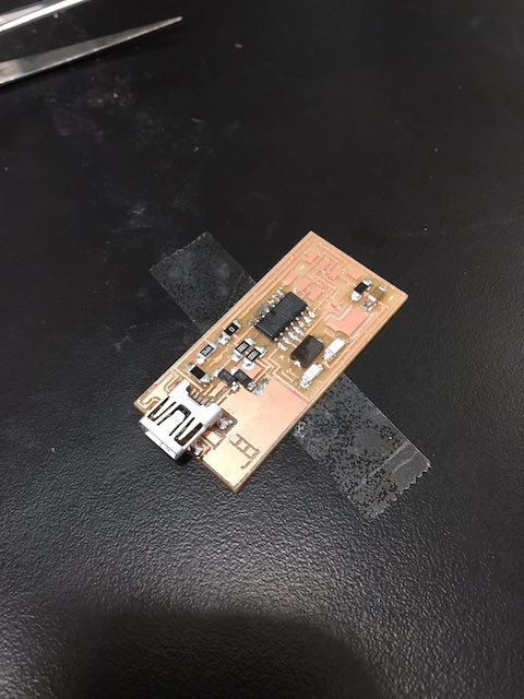
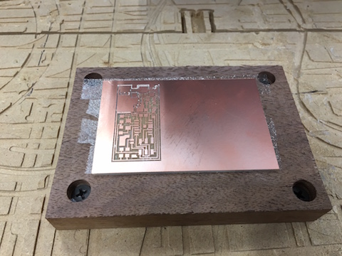
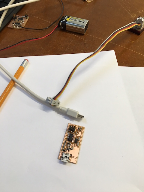
I returned the next day, eager to retry the one method I was sure of -- make a new board and reeeeally hope it works. However, due to the previous two misadventures, I determined that a new, more interesting design was in order. Initially, this meant designing a new board. About 15 mins into the process, I realized that, whilst it was a great deal of fun to draw board-shaped pictures, I still had no idea of how the boards worked, and how to even begin constructing my own circuit. Following this enlightenment, I scrunched up my drawings, and returned to using pre-made designs. I found a happy medium -- I used a new pre-made design. This time, I decided to use Andy's board design, as, according to Dixon, 'everyone who made it was successful'. As it so happens, this board had to be scrapped *just* as it was nearing the final stages. I discovered, at the last minute, that four of the chip's legs were connecting to ground, indicating a clear cutting mishap. So much for that. Note to self, an extra one minute spent inspecting the board before soldering can save thirty minutes later on. To see just how close the board was, see below.
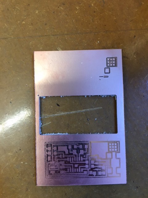
Before a successful board was built, there was time for just one more mishap. I tried using the Roland mill for the next board (4th). I failed to zero the z-axis correctly. This resulted in a very pretty board pattern, but not a single usable trace. Great.
Andy's design ended up working eventually. The second try (on the ShopBot) saw the board cut out correctly, soldered, and programmed. As it turns out, there may have been a software problem plaguing me all along. Initially, the board would program, but failed to program others (just like my 2nd) board. This was true when I programmed my board on a Mac, and on a Windows machine. Programming my board on a Linux machine, however, fixed the problem -- my board successfully programmed two other boards! This makes me wonder about board number two, the one that almost worked. Perhaps, if I re-solder the jumpers and program it on a Linux machine, it too will work. I haven't had a chance to test this yet, but will in the future. I have no intuition about this software problem, all I know is that it exists. If anyone else knows what was happening, I'd appreciate some enlightening.