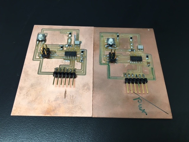
This week's assignment brought all of the ghosts of weeks' past back to haunt me (Halloween-themed vernacular!). Most specifically, it punished me for some key errors during the electronics design week. Firstly, a design flaw from the 'hello world' board that I made two weeks ago sucked up about 3-4hrs of my time. Whenever I connected the board to a computer, I was greeted with a popup informing me that USB ports had been shut down, due to a device 'drawing too much power'. Translated, my board was short-circuiting. As it turns out, I had mistakenly connected my button to a resistor in series (as opposed to in parallel, as would have been correct). To be completely honest, I still don't entirely understand why this is a problem (partially because I'm not sure why the resistor needed to be there at all), but I fully believed the two TAs who told me that it was a dire problem indeed, and that I needed to re-mill my board. Pictured below, Tiffany, circuit-board extraordinaire and professional short-circuit debugger.
After fixing the design flaw (in Eagle), re-milling and re-stuffing, I had a brand-new, functional board! Or so I thought... Plugging the board into a computer revealed that, once again, the board was short circuiting. This time, as there was no obvious design flaw, I fetched a voltmeter (I think), a TA (Tiffany), switched the voltmeter (might've been something else) to 'beep' mode, and began testing for things connected to things that they shouldn't have been connected to. Fast forward 2hrs of head-scratching -- everything was connected to everything that it wasn't supposed to be connected to. I clearly hadn't spent enough time analyzing the tool path generated by the fab module before hitting send, because my board had milled with about 10-12 joined connections (lines that had not been separated from adjacent lines, probably because I should've tricked the Roland Mill into thinking it had a slightly smaller endmill). Every pin was connected to every other pin beneath the ATTINY, there was a line beneath the capacitor connecting its two ends, there were various lines connecting the pins of the ISP header, etc. Thankfully, I didn't need to re-mill and redesign the board again. Using my trusty, totally-not-a-supervillian-weapon-of-mass-destruction heatgun, I removed components from the board, severed the offending lines with an xacto, and resoldered the components. It was with much apprehension that I plugged in the 'hello world' board for the umpteenth time; bracing myself for the inevitable, crushing despair that so often accompanied this choice of action... IT WORKED. The board did not short-circuit, and avrdude was aware of the board's existence. All in all, not bad for over 7hrs of work (insert crying emoji). Pictured below: the moment.
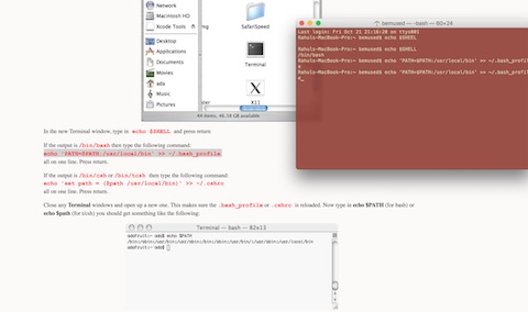
Next up, it was time to programme the board. Thanks to a short introduction from Tiffany and a year of CS, I wasn't too intimidated by this process. I didn't have time to test a particularly challenging code this week, but, as shall soon be revealed, even the simple code didn't exactly go as planned. The first serious challenge was that of installing avrdude on a Mac -- surprisingly non-trivial. Neil's fab site linked to the Ubuntu download page, and the internet seemed only to care abut Linux and Windows. Thankfully, Rob Hart (who installed avrdude on the Harvard section Mac) had a suggested course of action, starting with homebrew. If you, dear reader, are both a mac owner and prospective programmer then I recommend the following: avr-gcc tutorial.
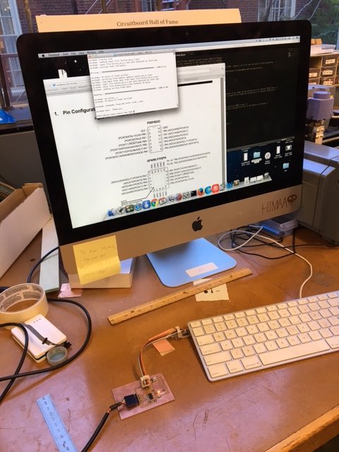
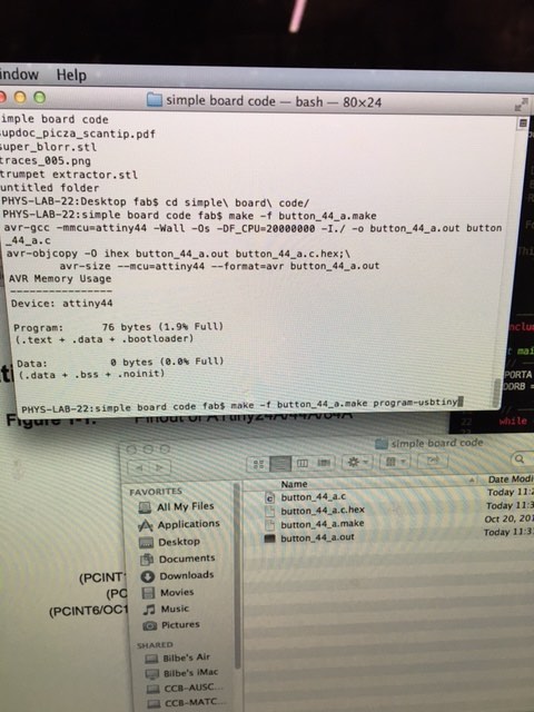
Firstly, just to confirm that everything was copacetic, I connected the programmer and 'hello world' board and attempted to load a simple programme (not one that was customized for the board, just something to load.) It worked. Pictured below is the command used to load a programme that is compiled by button_44_a.make. The exact command, for easy reading, is: make -f button_44_a.make . Once that command executed successfully, I ran: make -f button_44_a.make program-usbtiny .
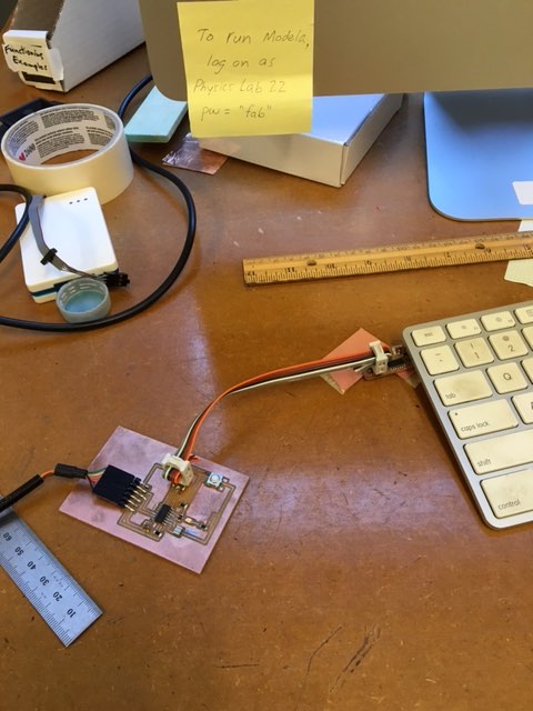
One other note: Neil has a convention when attaching boards via the 6-pin header. This is important, as the boards won't read if not connected with the correct orientation. Obviously, it's not too difficult to disconnect and reconnect the boards if connected incorrectly initially, but having a convention will save time. Pictured below is the correct orientation for my boards.
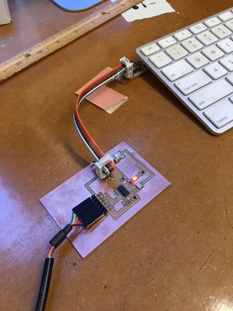
Once the board had been programmed with a dummy programme (proving that everything was connecting correctly) I set out to edit a simple programme, such that it would work for my board. I used Rob's button_44_a code -- simple code that switched an LED on the board off/on at the press of a button. Editing the code was quite straightforward, it merely entailed understanding the representation of the various pins in the code, and changing the pins that the code 'spoke' to, such that they matched the pins used on the board. It was necessary to consult the ATTINY datasheet in order to understand ports, and determine which pins were being used. Finslly, I uploaded the code. End result, the LED lit up, but pressing the button did nothing to switch the LED on/off. Will debug in the future.
Editor's note: buried by a midterm this week... Had to settle for the bare minimum (particularly considering how long debugging the board took). Cool things will be made in the future.