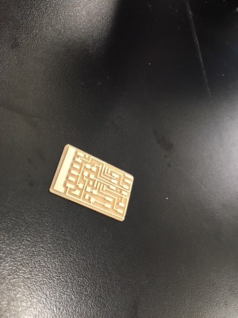
I started this week by fabricating the step response board from the class page -- I wanted to get some understanding for how the board works before attempting to make my own. The fabrication process was exactly as expected from previous weeks, entirely mechanical. The only new comment is -- as I said earlier, the Modela is terrible. Use the ShopBot, save yourself pain.
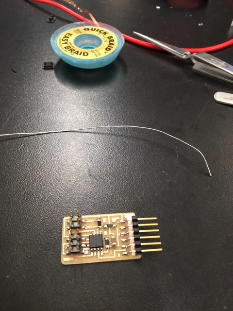
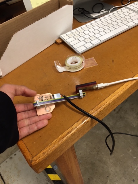
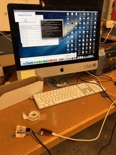
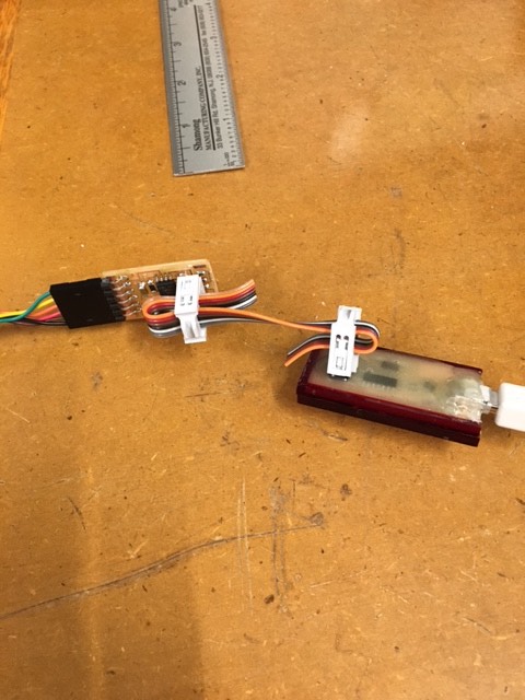
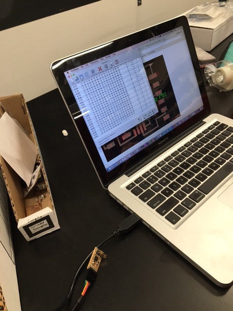
Following the milling, I programmed it (using the same commands from week7). Then, I plugged it into Rob's laptop and used CoolTerm (great software) to visualize the data being sent out by the board. It was very interesting to see the code in action. After much staring (and explanations from Rob), I came to understand how Neil's code sent out 4 bits as 'markers', then sent out 4 bits of data. When the board was touched, the 4 bits of data changed, showing how the board was picking up the step response.
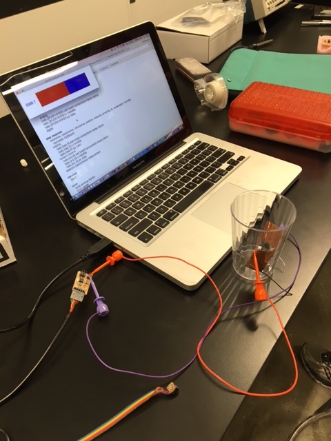
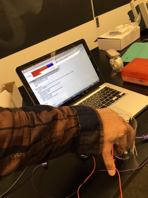
Finally, just to fully accomplish this week's assignment, I 'measured something'. I attached two pads to the board, then attached one pad to each side of a cup. When I placed my hand in the cup (thus affecting the electric field), the board measure the step response, and showed up clearly on Neil's python script.
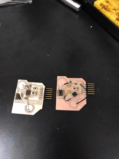
I decided on one primary change to Neil's step resonse board -- I wanted two copper plates on the surface of the board, as opposed to the 2x4 header that connected to some external plate. Reason being, I'm considering some kind of interactive tech for the final project, so I wanted to see how I could design a responsive surface. Designing the board was no different than the process outlined in week 7 on this site -- Eagle, add components, determine logic, route.
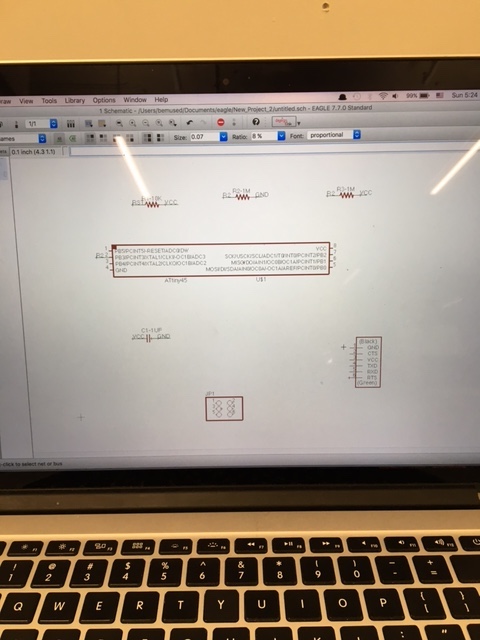
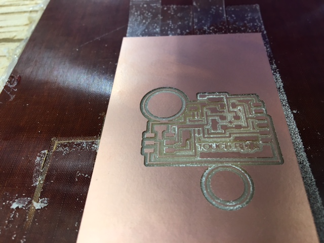
However, I did encounter a problem (also an issue in week 7...) -- routing. The circuit ended up being more complex than I had thought, and so routing was a non-trivial task. I made two mistakes: Firstly, I put some traces too close to each other. Secondly, instead of adding 0 ohm resistors where neccessary, I got lazy, and decided to connect distant components with jumper wires. Wires aren't always terrible, but in certain instances they are. Connecting a wire to a single pin on an attiny45 is painful. I will never try to do that again. Similarly, connecting wires to any components that are close to other components is very challenging -- even the slightest contact would result in a short circuit. Ultimately, the board did not work. I discovered that the ShopBot had not cut two of the traces correctly -- almost certainly because I had them too close together in the board design. Note, this was a design problem. This is not an excuse to use the Modela instead of the ShopBot. Boycott the Modela!
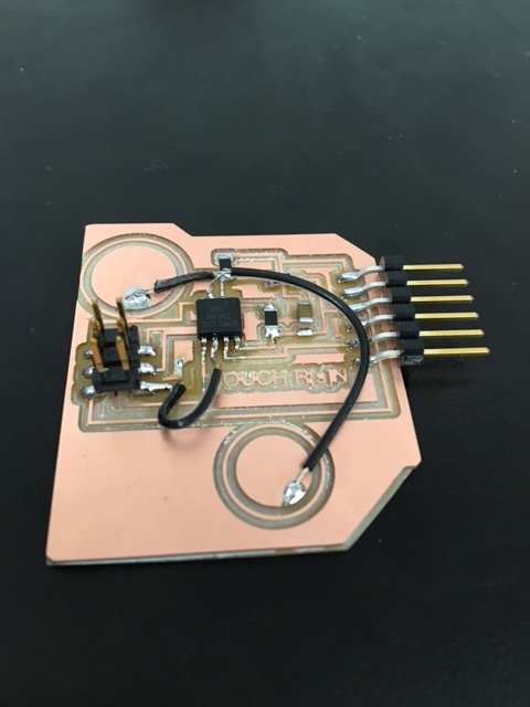
Following the initial failure, I quit, and vowed to come back at later date. I returned on Tuesday, election night, armed with three electronic devices to stream election results, and a burning desire to finish the board quickly so that I could keep on obsessing over the election. Surprisingly, the board worked perfectly the second time -- after moving the traces and adding some 0 ohm resistors, the traces machined correctly, I soldered correctly, and the board programmed correctly. However, Trump was elected, so we all lost anyways. Final Project idea! A wearable capacitance board for women, so that, when Trump tries to grab them, we'll know.