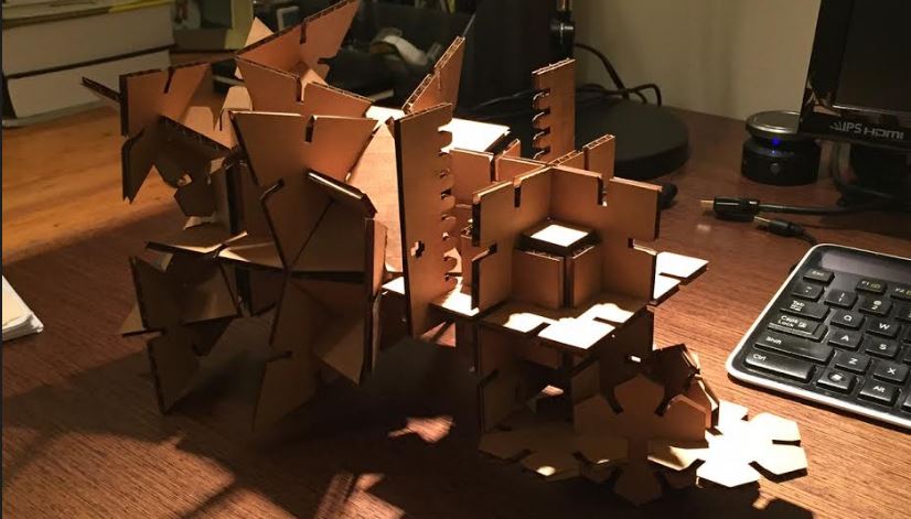
Laser Cutting / Press-Fit Kit
This week was laser cutting 101 with the end goal of creating a a press-fit kit. Neil started off the week showing us a bunch of different fixtures and discussed their pros and cons. Being a bit of an overachiever at heart I decided to try to do the "second best" one he showed us. That was a bad idea to start with. I decided to work in Solidworks (see week1 for reasoning). And unfortunately, Solidworks makes it quite easy to overconstrain sketches which becomes a huge pain if you are trying to make tons of things perpendicular or parrallel etc. It probably would have been a better idea to take a CSG approach and build it up section by section cutting off what I don't want. BUT, I didn't take that route and ran into a bunch of problems trying to pattern and copy the original sketch to create multi-sided pieces. That said, looking back now that I figured out how to do it with a more basic design - and worked through the kinks and perculiarities of Solidworks I would probably be able to make it work. So lesson learned -- start simple. I actually went back and fixed the CAD drawing after I figured out how to do the easier fixture as described later! See below for fixed fancy fixture:
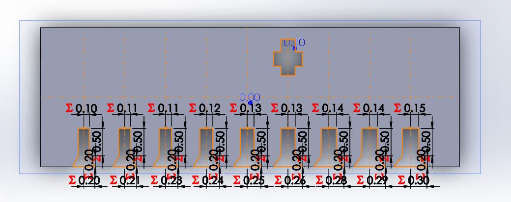
After failing at the more advanced fixture for a while I moved to a more simple fixture and got a bit more careful on only defining relationships between the exact few lines I actually need. This prevented the overconstraining error and allowed me to become relatively quick at making different shapes with the simple chamfered slot. I was gone all weekend so did a bunch of CAD ahead of getting back to campus so I could start cutting. I decided to create a size testing model to have the whole size I though should be correct and 5% adjustments both up and down up to 20% to quickly find the best size. I also made a triangle, a hexagon and a square part. They are all parametrically designed using global variables and equations which are relatively simple to use and will allow me to adjust to laser kerf and cardboard width quickly once I'm back on campus. The parts I designed over the weekend can be seem below:
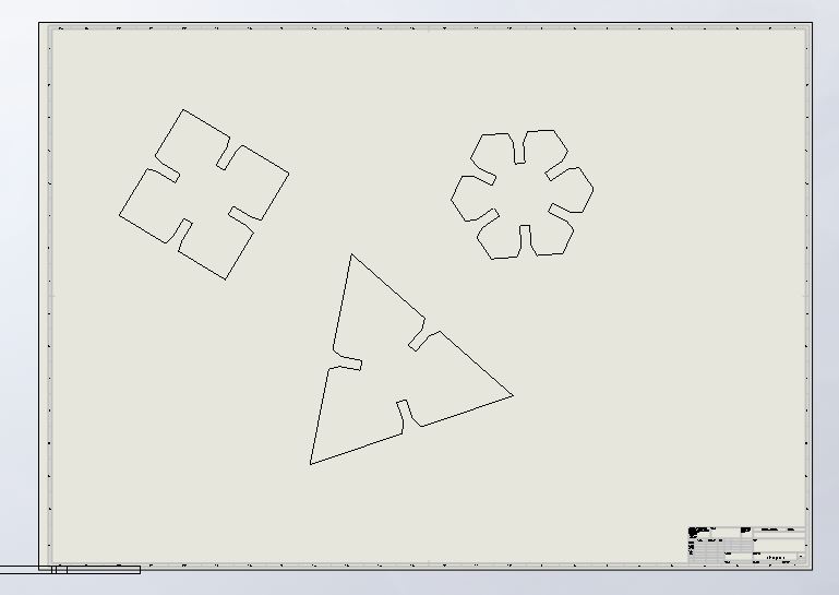
In order to export Solidworks 3D files as flat 2D images you need to make a drawing from the part. I tended to simply use the top view and call it a day. You can add all open solidworks parts to the same drawing which makes it far easier to send multiple parts to the laser cutter at the same time. See drawing file below:
Once you have your drawing you need to export it to the file type that the software on the machine attached to the laser cutter uses (in my case .DXF for CorelDRAW). I found that when I imported the DXF it came with the whole border markings and legend in the bottom right which I would just have to delete. Then I also noticed that the scaling was off so I had to resize it by X% based on how off the scaling was on import (mine were usually twice as big -- not sure if that was a Solidworks of CorelDRAW error but it was very easy to fix AND important to check). Some quick CorelDRAW tips follow:
- CNTRL+G will group items (should be familiar for PPT users) -- this is useful to group seperate parts if you import multiple parts.
- CNTRL+D will duplicate an item and if the next thing you do is move that item (aka itemDup is 3 pixels to the left of itemOriginal) then the next CNTRL+D will create another duplicate at the same offset (aka itemDup2 is now 3 pixels to the left of itemDum). So once you get this right you can create a whole row of a part with just a bunch fo CNTRL+Ds
- Make sure your lines are "hairline" in width and that all of your colors map to true RGB colors. Then you can use the preferences on the print screen to map colors to laser intensities and speeds.
So now with all of the software setup out of the way it was time for printing. It was time to smell that nice campfire smell as we burn away at the cardboard! This was actually way more successful and easier than I expected -- obviously though there were a few learnings!
First off printing the fixture size test piece first was super helpful. It allowed me to test the hole sizes on that thickness of cardbaord and then let me update all of my models to the optimal thickness. Starting at wholeWidth = cardboardThickness - 2 * LaserKerf was a great first guess. Including the +/- 5%,10%,15% and 20% allowed me to compensate for innacuracies in the translation of Solidworks Part --> Laser Cut and for getting the Kerf or cardboardThickness wrong. It turned out that the laser thickness was a little bigger than I first measured but also that the kerf was bigger so it all worked out perfectly at +/- 0% for me! Below you can see the result of my first test print of shapes after checking the with test piece:
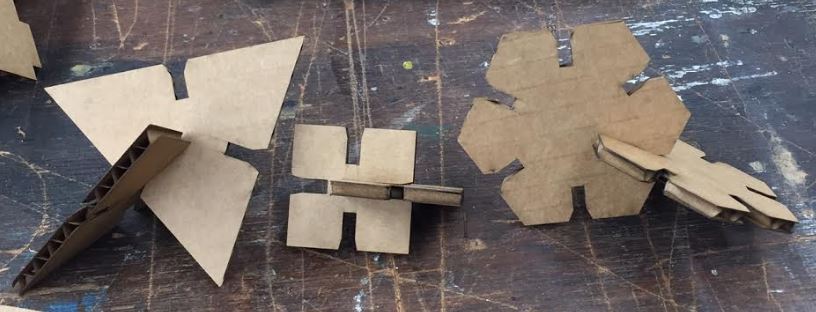
It all looks great in the picture (maybe) but in my first attemtp I forgot to account for the fact that when you conncet up multiple pieces there needs to be space in the center of the piece for all of the inserts to attach. I got lucky in that my triangle piece was perfect, while my square was too small, and my hexagon was too big (if you wanted relatively perfect fittings for tiling). That said, with my nicely parametric CAD, this was a breeze to fit, all I did was write a formula for the overal shape dimmension and the drawing file automagically updated and I just reexported into DXF and reimported into CorelDRAW and printed it all over again. Of course this time I had made the size so perfect that only one direction could fit all the way in, so it was back to Solidworks Part -> Solidworks Drawing -> CorelDRAW and then finally it was working. You can see the initial difference in the whole depth vs size of piece depth in the following image:
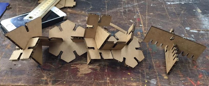
One last thing I leared is to ALWAYS CHECK THE SIZE OF THE CARDBOARD! On my second attempt, the new piece of cardboard had compacted a bit in storage and had a smaller width than the first one and so my fixtures were too loose. Selecting an appropriate piece of cardboard / adjusting the widths in my CAD file for the cardboard on the third go-around worked perfectly and I then printed out a full sheet of parts. I then went home and played around with them for a little and endedup making this creature like thing below:
In conclusion, press-fit on the laser cutter is really fun, relatively easy, and very satisfying. The big trick is to make parametric models so you can change around parameters easily and quickly when you need to iterate! Also start with something on the easier side to get the hang of things before you try something hard!

