Basic Circuit Design or Hello Eagle
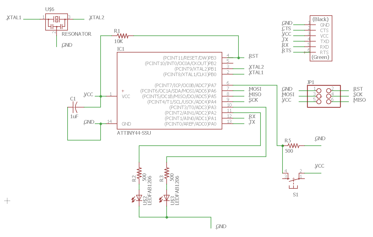
I decided that I wanted to use the three free pins to 1) have a button as input and 2+3) have two LEDs to count to 4 in binary. Therefore it was time to learn Eagle! I was very confused by the interface at first but went through the SparkFun Tutorial on the schematic engine and on the board layout engine which made everything crystal clear! It is literally all you need to get this week's assignment done in Eagle. I STRONGLY suggest using the tutorials and reading through it once before starting -- I didn't read it all at first and missed the best feature of the schematic naming the wires to autoconnect them! As such I made an ugly thing that was hard to reason about. So I redid it with names and it was so much cleaner! See below:

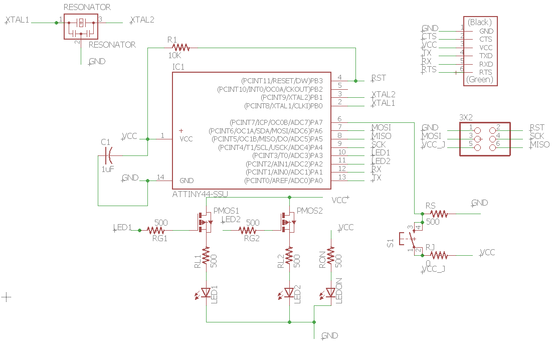
Next it was time to start routing. The first time through I went one component at a time without thinking much about things and I got pretty stuck. I also didn't realize you could add more components into the schemtic that would auto-pop-up on the routing iteratively. But anyway I started over and started with VCC and GND connections and then started attaching components one area at a time. I ended up only needing to add in one zero-ohm resistor to make one jump and otherwise got it all routed up. Note: ROUTING IS HARD. This takes a while althoguh I'm sure there is an expertise in doing it well. Also I used the Sparkfun Design Rules Checker file which found one route that was messed up that I couldn't see as it was connected weird under a pad. So I highly suggest taking the time to do that step. I also highly suggest checking with an circuits knowledgeable person to check your schematic as I had my mosfets (which I added to control the LEDs because why not) backwards (P vs N type -- they are very specific). I also found out from Rob that all of the programming pins (except RST)can be duel purposed once the device is done programming to do other things -- I will definitely leverage this in the future to get more out of a board but decided not to re-do things now. Rob also mentioned that my extra pullup/pulldown resistors aren't strictyl neccessary because the Attiny has pullup resistors in it already (how cool). Again I decided not to change it for now but really nice to know! Routes and updated schematic below:

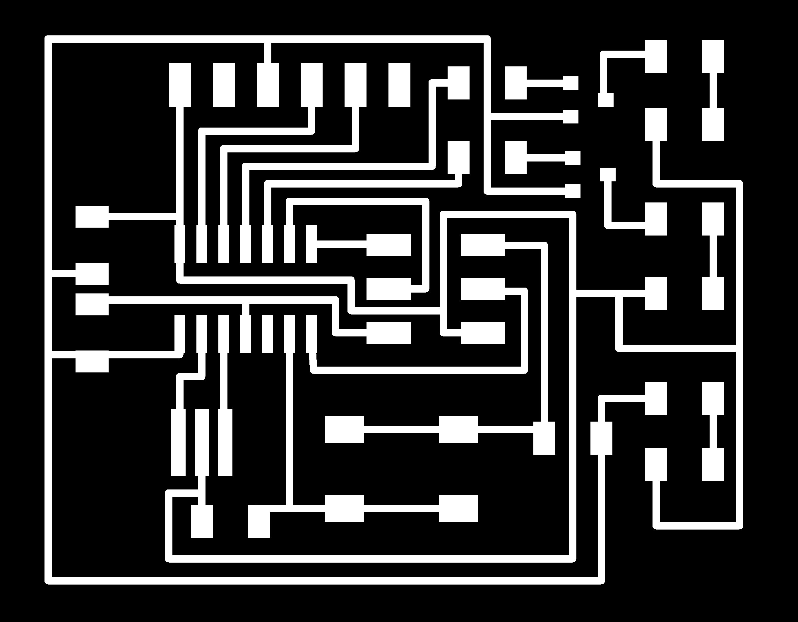
Then it was time to export the image from Eagle and send it to the mill. This was actually not very clear on how to do but after asking a TA it turns out there is a button that has three squares of different colors on it and from there you can hide all but the traces or all but the outline etc. And when the right things are showing you can export it as an image. One thing to note is that the original eagle export for some reason added a ton of extra black space on the left but after fiddling with components a bit it decided to stop doing that.Not sure why or how that worked out. Anyway, then I sent that image to the mill. At this point I like the Roland mill and understand the design flow through Neil's fabmodules pretty well. That said, in the end it failed. I didn't inspect the cut path close enough and it totally missed some of the traces merging them with some pads.
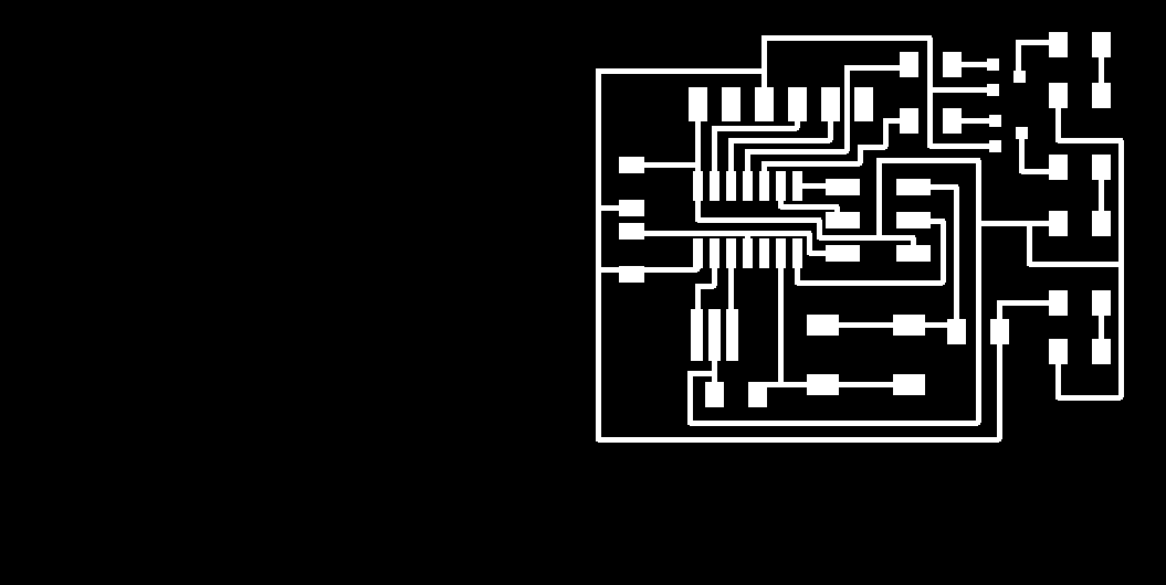
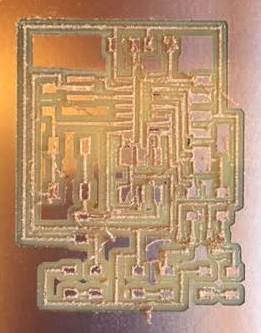
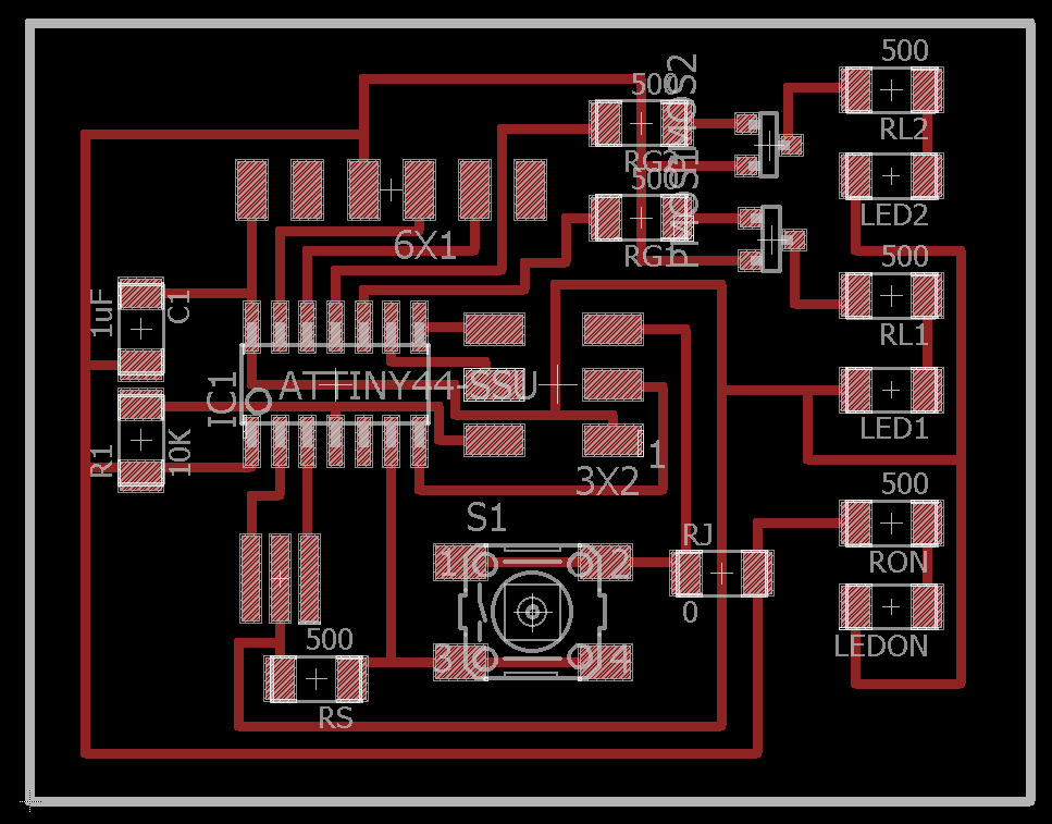
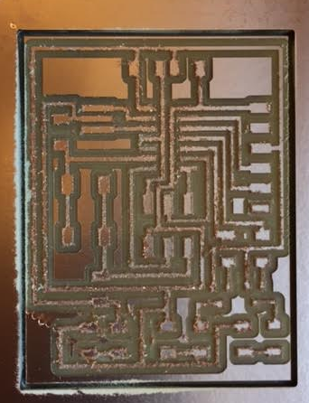
It turns out my error was probably driven by the fact that I exported the image with too little of a DPI so it just wasn't clear enough to Neil's program on how to make the cuts. I thought the cuts looked weird but I was too confident in my process and not careful enough (my fault). So, just to be safe on the next pass, I moved one trace around (the final image is what is shown above). When re-exporting with the higher DPI it worked much better. After a second mill we had a fully cut set of traces. Of course per usual the Z was a hair off so I needed to use the exacto knife to finish the outline cut but overall a pretty simple milling process. If you look at the images below closely you can see how the higher DPI found more / better detail on the traces in general. Here is the final schematic and board file.
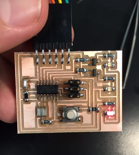
Now it was time to stuff the board! After practice the other week this went really well as again I started with the components that most got in the way / were in the center (3x2 then attiny then the 6 pin header then resonator and its resistor then button and then everything else working from placed components out. Then I plugged it in a whamo we have light on the power resistor. Because I switched out the mosfets at the last second and the attiny isn't programmed the blue lights are meta-stable and sometimes turn on but touching the board will fix that undeterminism. Hopefully with some programming this will work perfectly, we shall see!

If I have some time I am going to try to program it as well -- if not I will punt that to the week where we are supposed to learn how to program it!
Update: I did run out of time but I programmed it during week7!
Back