Week 3: Electronics Production
Introduction
This week, I made an in-circuit programmer. This circuit will be used to program the microcontrollers on other circuits that I will be making this semester. The main focus this week is to physically make the circuit boards, which involves milling the board using the Roland Modela milling machine and stuffing the board (soldering all the components onto the board).
Phase 1: Design of the board
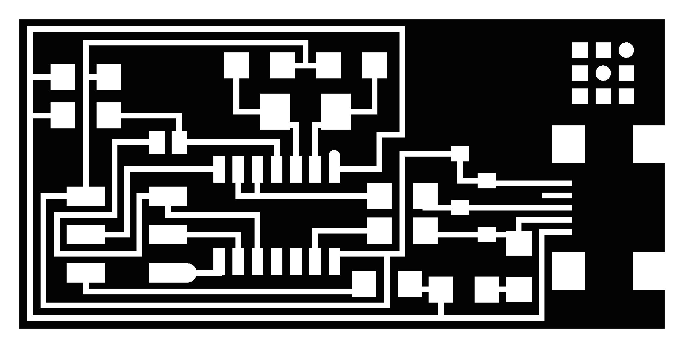
As mentioned, the main focus this week is to make the board, so designs were already given. In Week 4, I will be designing my own board. The board traces and interior are below:

Phase 2: Milling the board
-
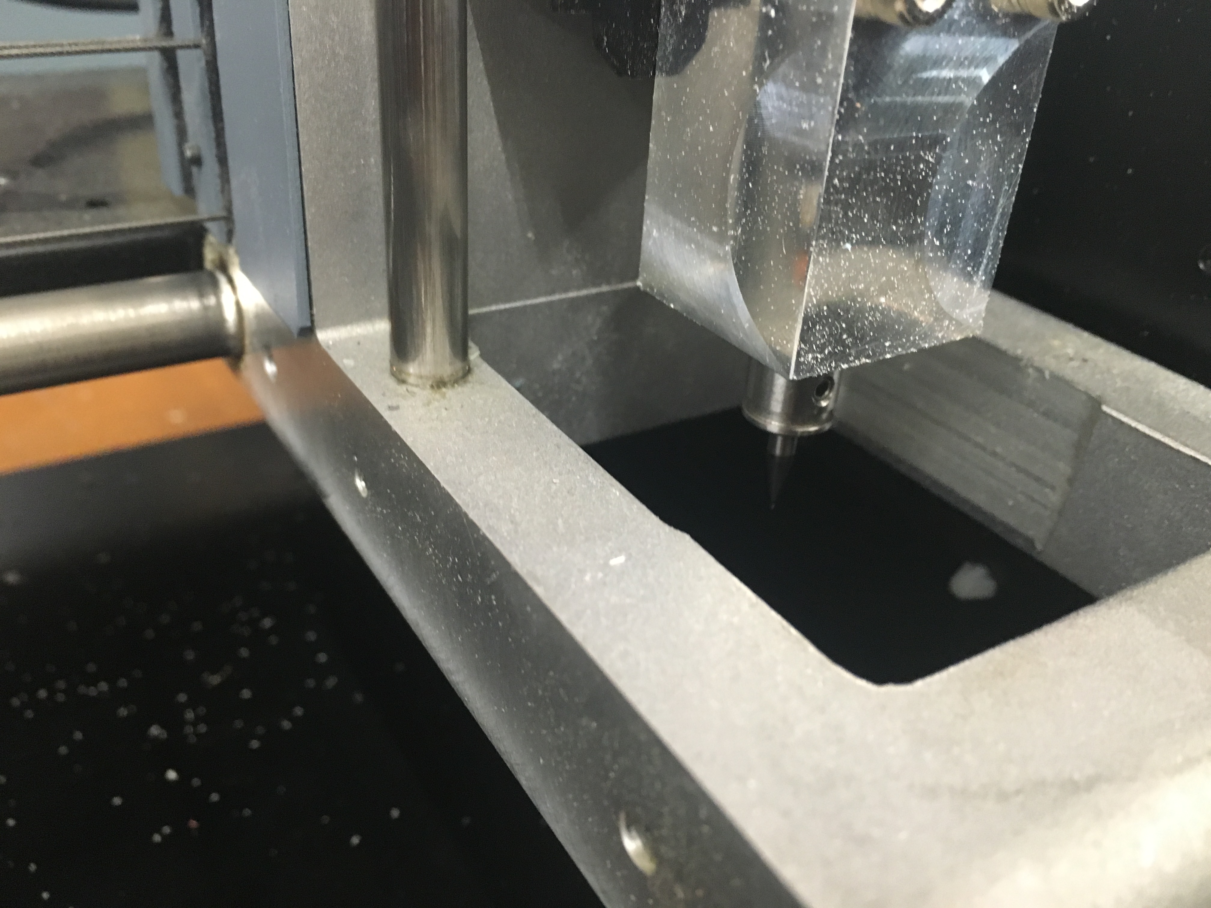
Make sure that there is a sacrificial board underneath the board that you are milling (see pic below). This is to protect the machine if it drills throughout your circuit board
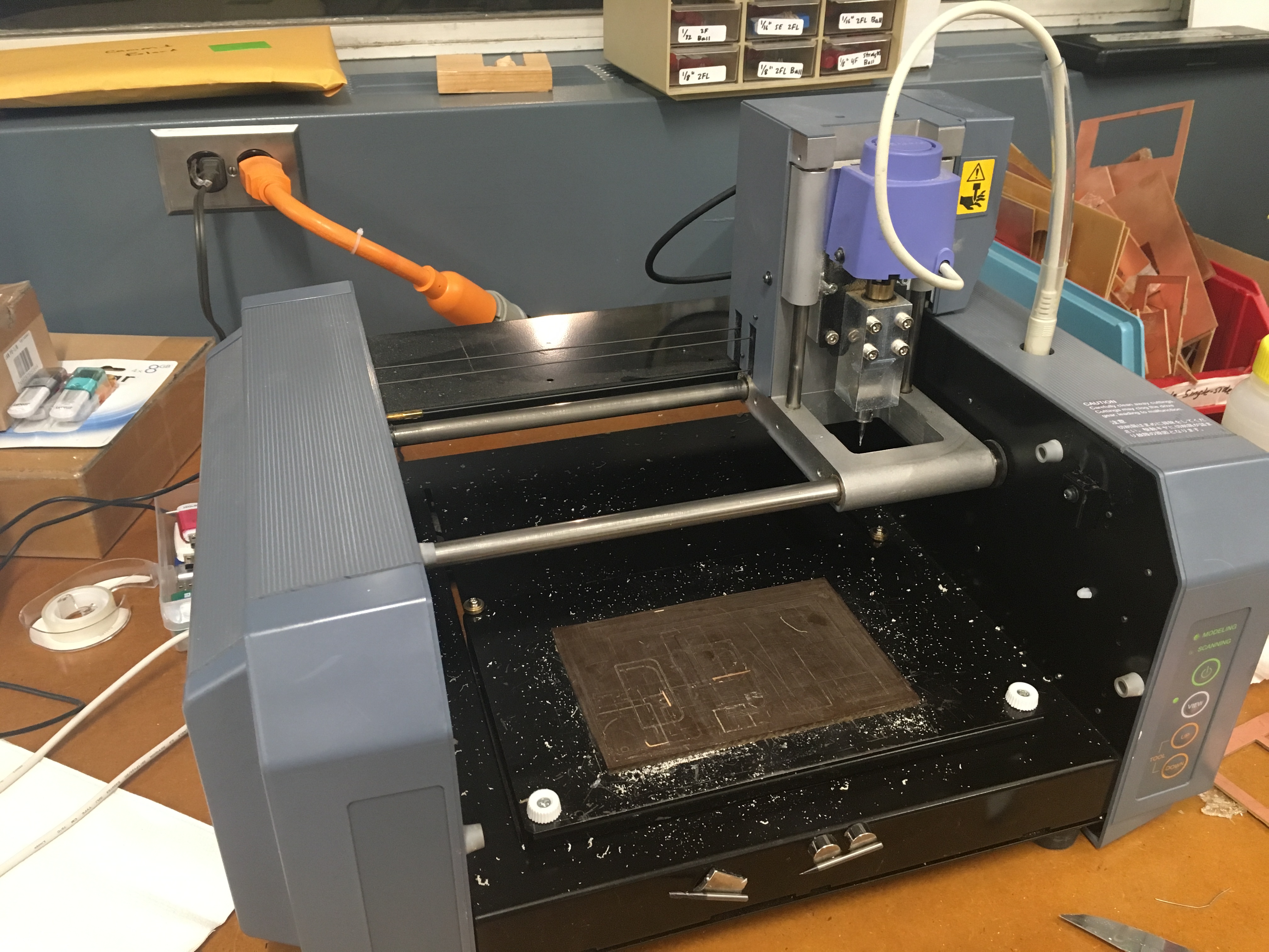
Milling machine with sacrificial board -
Get a square piece of FR1 (paper based copper plate) and use double sided tape to stick it to the sacrificial board. This keeps the board in place when it is drilling – it also helps keep the board flat.
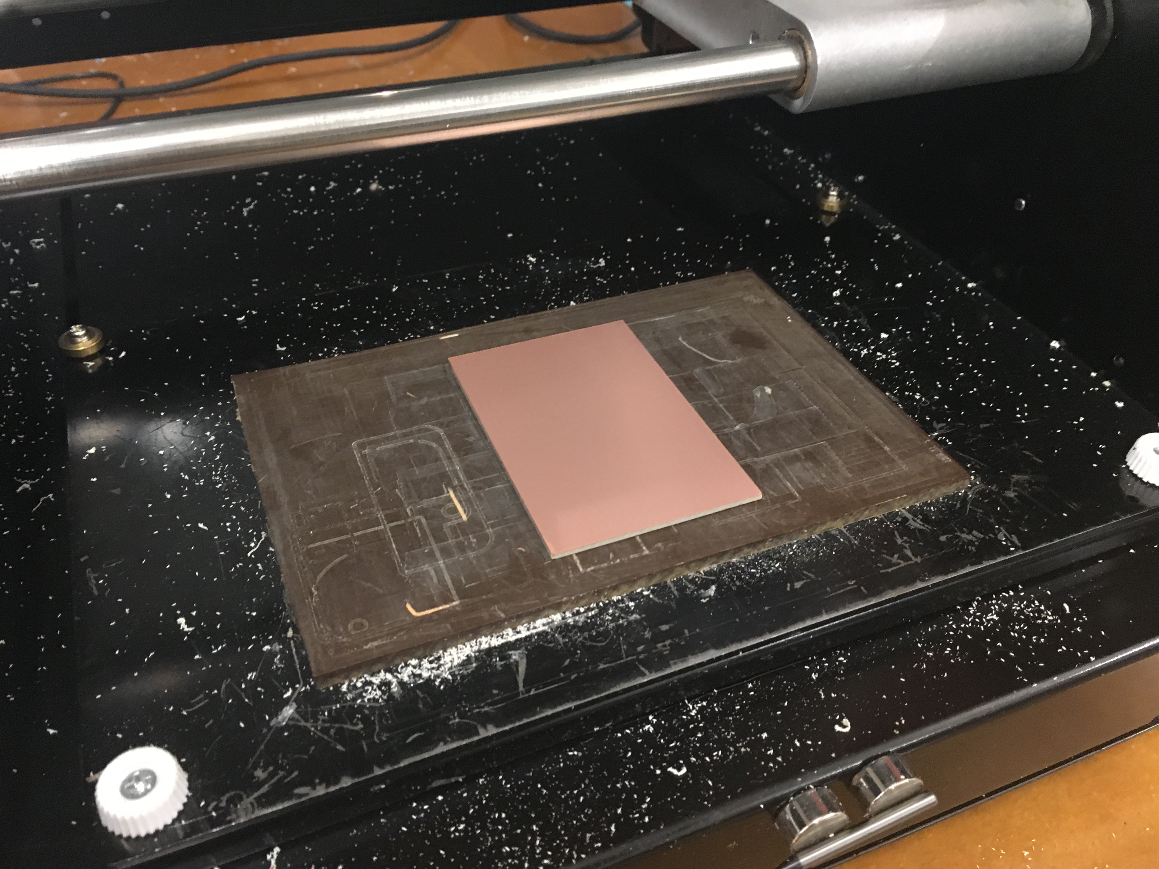
Copper plate stuck with tape -
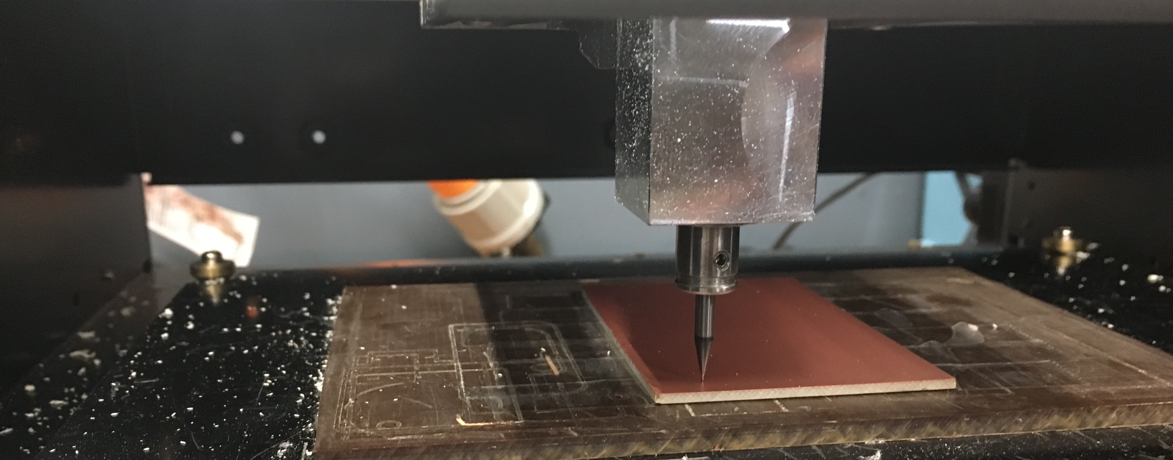
Place a 1/64 bit in the right position. The 1/64 end bit is used for the traces and the 1/32 bit is used for the outline of the board. To do this, keep hold of the end mill and screw it in place. Keep hold of the end mill, because if it drops, it will break.
1/64 bit - Go to the fabmodules site and run the server
- At the fabmodules site, select the following options: Input: png (then upload the trace file) Output: Roland mill (.rml) Bit size: 1/64 ‘’ On the right hand side, select the machine RDX-20
- Zeroing: Now we need to zero the mill. On the fab modules site, you can input an x and y position and press ‘move to xy’ – the modela will move to the position. Then you want to zero the z axis. Move the modela downwards in the z direction until it is slightly above the board. Then unscrew the end mill and lower it down so that it touches the board. Now you can zero that.
- Make sure that the black/white of the image is correct. Black is negative (to be removed) and white is positive (to stay). If necessary, invert the image if your image is backwards.
- Calculate the path by clicking ‘calculate’
-
Run the milling machine!
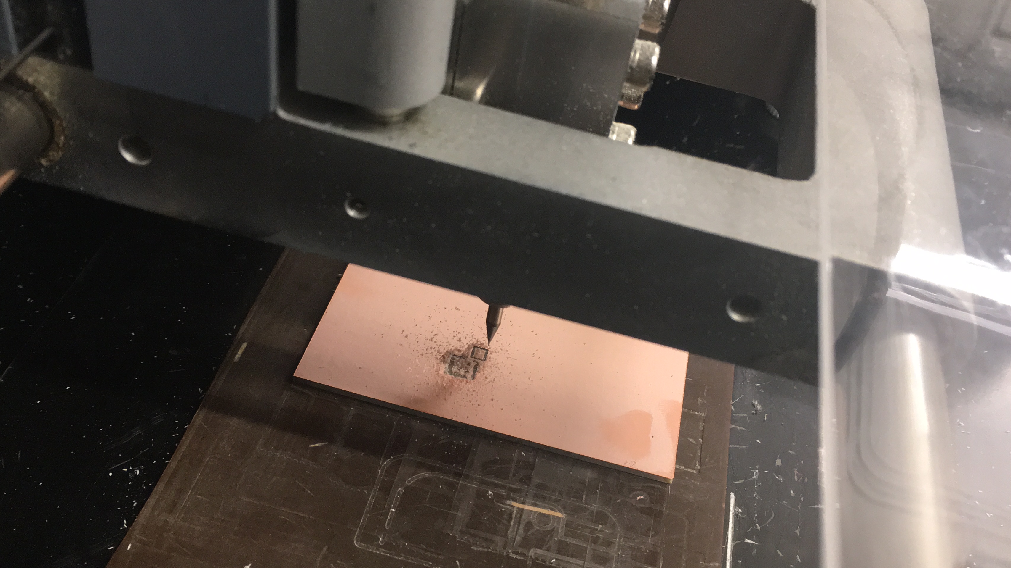
Machine in action 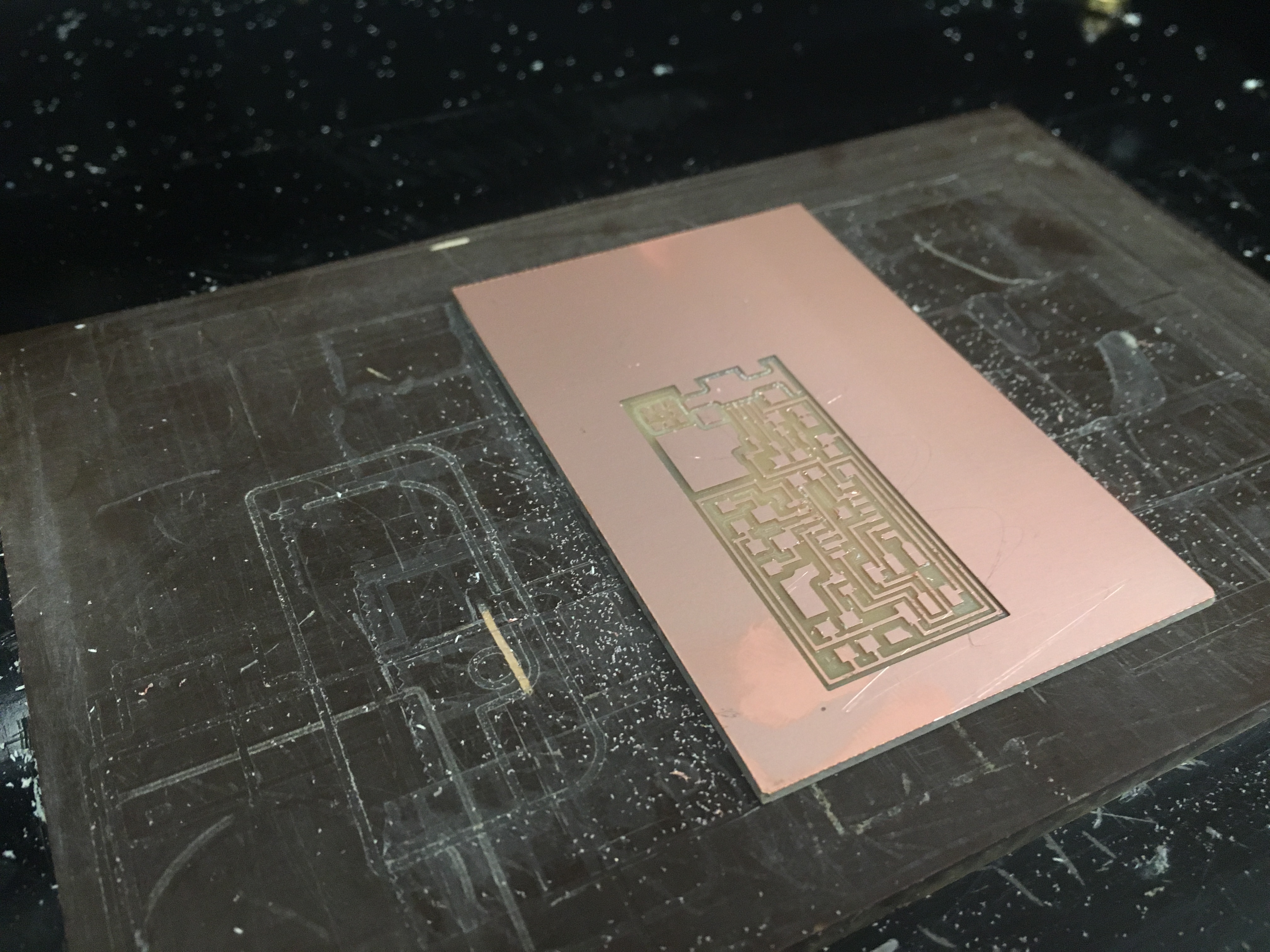
Board without outline - For the outline, replace the 1/64’’ bit with the 1/32’’ bit.
- Repeat steps 7 – 9 with the outline image
Preparing the board
Connecting the software to the machine
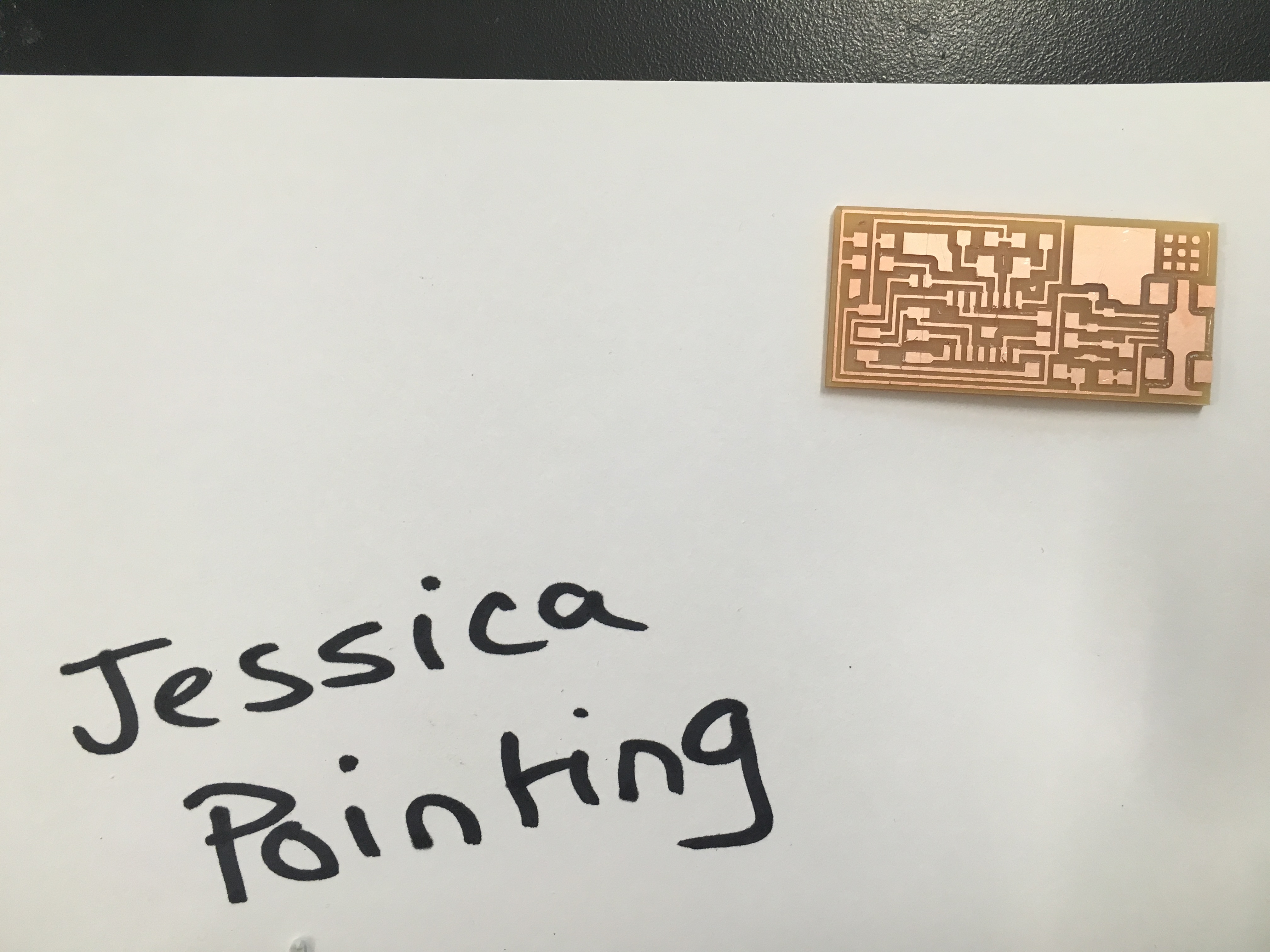
The Outline of the board
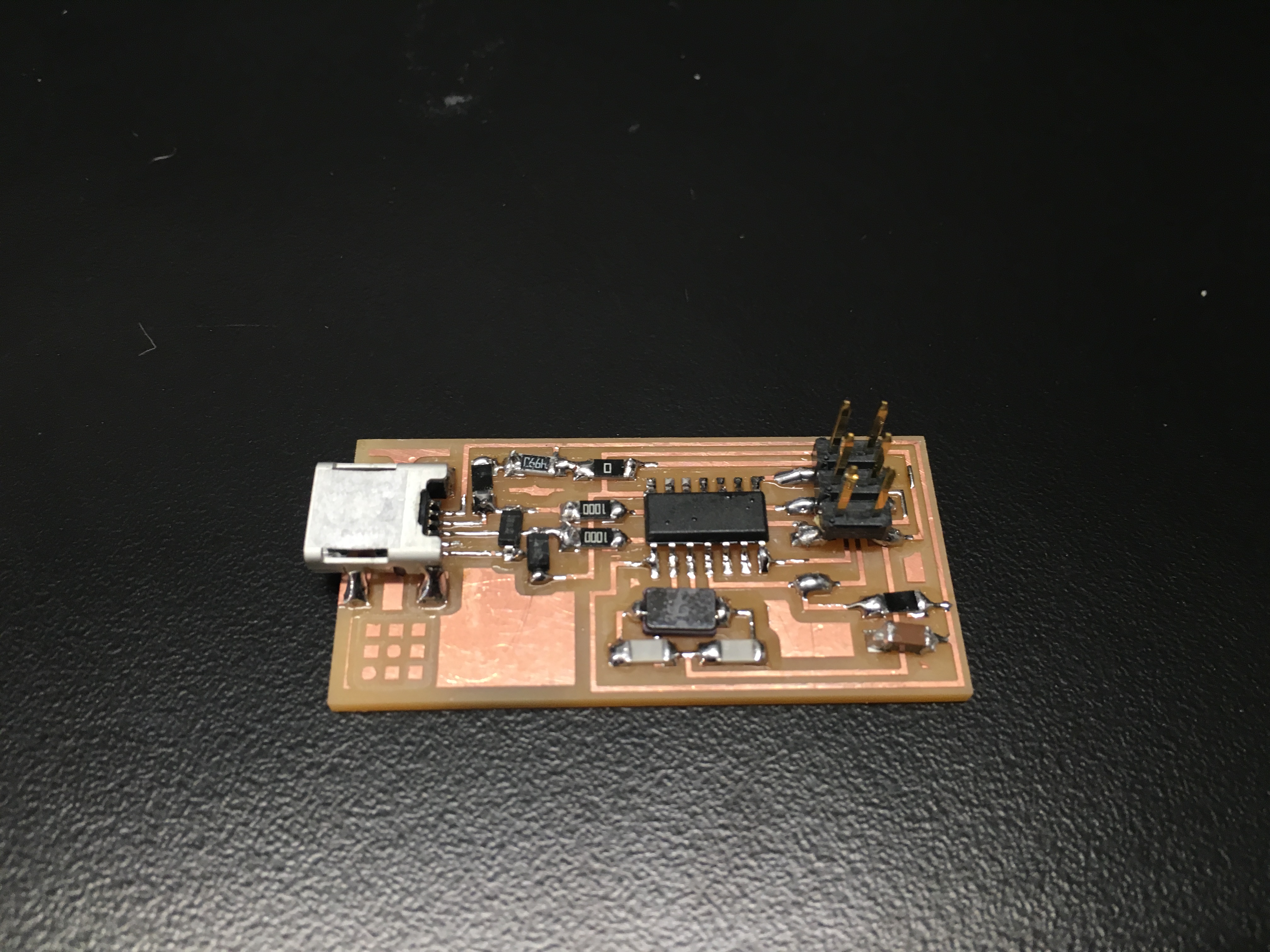
Phase 3: Soldering Components
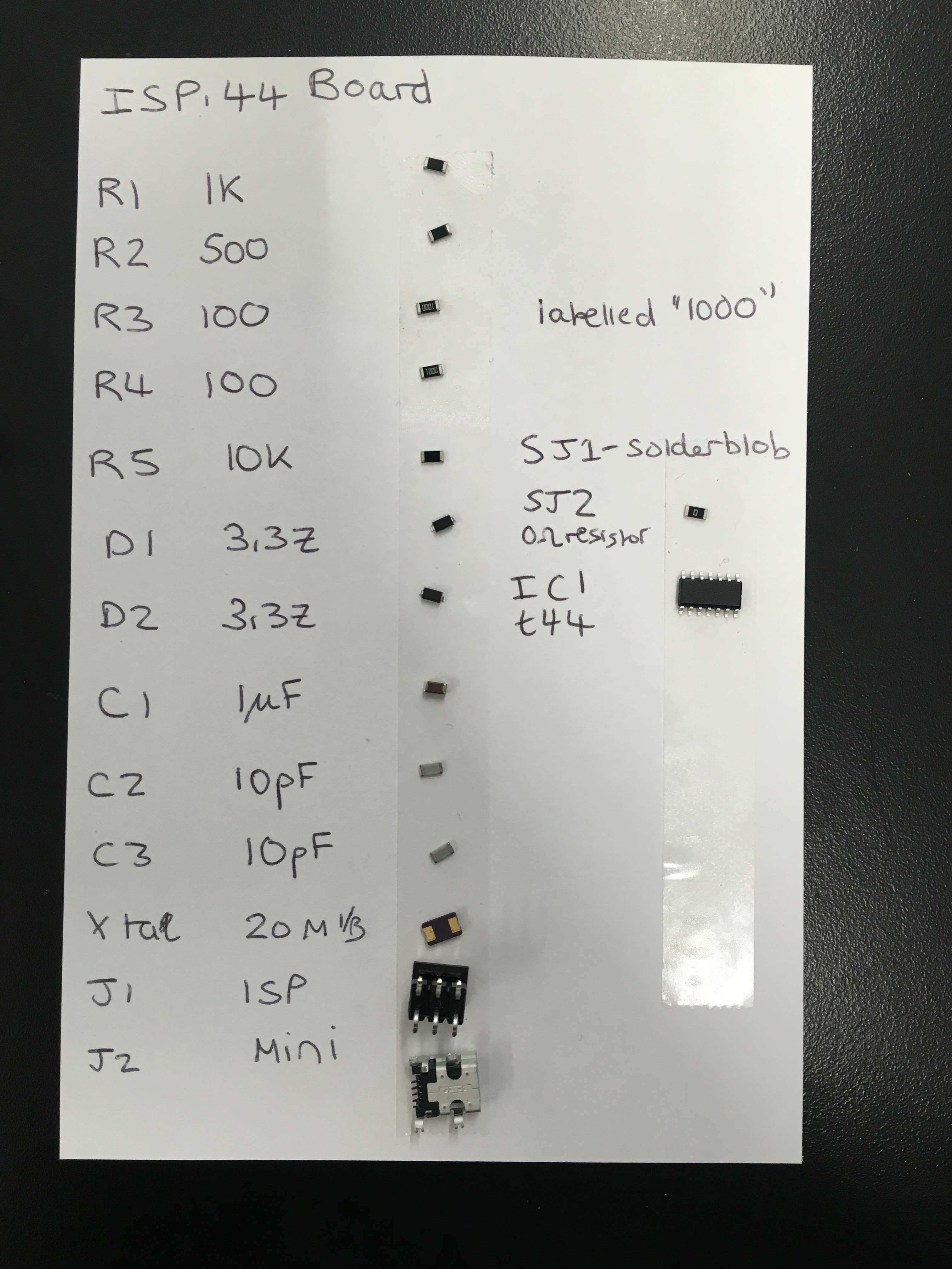
Soldering is really fun (once you get the hang of it)! First, prepare all the components for the board:
- Clean the board from any residue. You can do this by running it under a little bit of water, sanding it slightly or just simply blowing it.
- Start soldering with the interior components and then work your way outside.
- To solder, place a bit of iron on the copper that will be soldered
- Pick up the component with tweezers and place one side on the copper with the soldered iron
- Solder that side and make sure the component stays flat. Repeat on the other side(s) of the component.
Neil’s trick to solder components with small parts (such as the ISP). You can place a blob onto all of the parts and then use copper wire to remove the blob of solder. You will be left with perfectly soldered small parts!
Challenges:
One challenge I had was getting the header low enough to cut at the right depth of the board. To solve this, I changed the depth of the cut on the fabmodules site.
My board did not work multiple times. Solution: check the soldering! The first time my board did not work, there was a blob of solder connecting two parts that were not supposed to be connected. The second time, two resistors were connected with solder that were not supposed to be connected. It was hard to find these subtle solder blobs, but having a more careful eye removed those pesky things.
A great way to check the soldering is to use a voltage meter to tell you whether the right parts are connected and that there are no wrong connections.