Weeks ELEVEN & TWELVE.
Interface | Application Programming | Networking | Communications
Main Page
A Note on Constructivism and HTM{A}A
This is a course that is very much built on notions of constructivism--the doing, the building, and the making. And through these design processes, that is where we are learning the most. Of course, each week we encounter a recap of the last week through individual projects, and then move on to lecture. In these lectures, we go through basic terminology and unpack the vast range of possibilities that exist wthin that focus.
And as reflected through the sentiments and sporadic|dwindling attendance, these lectures feel less productive in our abiliity to create. Of course, there is always variance from one person to the next, but for those of us with little to no background, where the learning curve from here to there resembles a wall, this becomes increasingly taxing and frustrating.
Through all of this, I mean to bring attention that I have realized very much for me, this learning process through doing, building and making, also requires a sitting down and thinking, listening, and reading. There is this notion that constructivist approaches take on purely the physical or technological making, and upon reflection you learn. Of course this is true, but in a course that caters to people who have a stepping stone into these thematics already (ie have an understanding of how electricity works in a circuit), the learning curve seems less fatal.
Again, all of this to say, that my creating and learning process is not always going to be relfected in the building of circuitry and creation of items that are wowable. In other words, my learning and creation will not always be visible to another person's eye. The preocess that I undergo to getting from here to somewhere close to over there, may look very different and take very different shape.
I think that is something fundamental to this notion of constructivism, and something that perhaps should be acknowledged a bit more, whether externally or internally. Anyhows...
Where Have I Been?
Over most of the course relating to electronics, I've felt in a bit of a tiff. A bit bigger than a bit, I must say.
Learning a new language, learning to unpack and tweak the writings in a new language, that has so many moving parts. Like I said a wall. But what I found extraordinarily helpful was sititng down with a TF and unpacking what specifically this stuff means and why it matters. Being told over and over again to read the data sheet isn't very helpful. But being in a place to see how and when the data sheet should be used, I can see clearly now why I was told those things.
I sat down with Rob Hart and TA Joe Negri to go over these fundamentals in depth. And I know with certainty if I had not done either of those things, I would be still be aimlessly wandering, crossing my fingers that the semester sped up and finally finished. Thankfully, I decided to take my learning into my own hands as opposed to letting myself be moved in the ways that the course structure offered.
What Did You Do?
Before Making, Building Foundations
Sitting down with these two allowed me to unpack the code in a way that made sense to me, that offered me the agency to know what it was that I was doing while making changes, rather than working and moving arbitrarily. Additionally, with regards to the electronics circuitry pieces, I decided to sit down and actually unpack most of the basic components (whose position I thought were fleeting and more or less not too important) and beigin by focusing on schematics. Not even jumping into Eagle, how would I be able to begin thinking about a schematic was in a static space before jumping in and designing a circuit board using software.
Here are some photos of a few of the schematics that I drew in practicing:
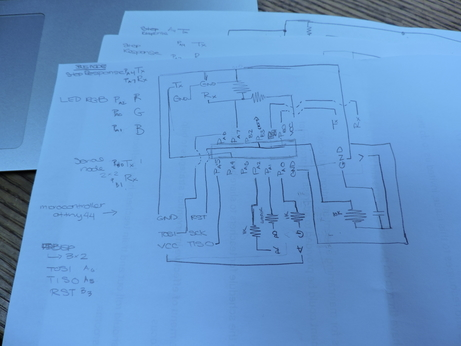
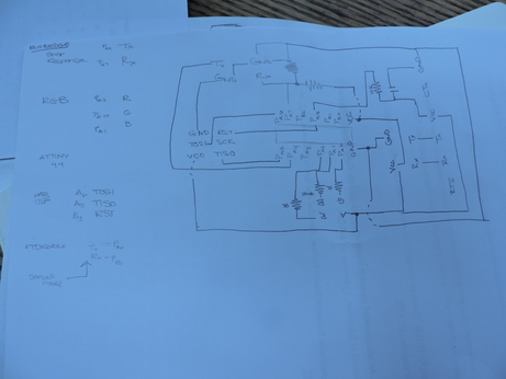
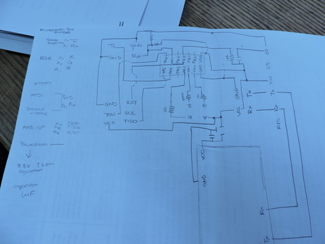
I then jumped into Eagle next to begin to design a board that would combine my Input and Output of Choice--Step Response and RGB LED. And again checking back with Rob to unpack how to determine mistakes I've made in the setup, to identify problems in my design until well after the milling, stuffing, and "programming". This was helpful altogether, going through the process in more depth and detail of what it means to Design a Circuit Board .
Final Project Relations
as seen on Final Progress Progressions page
My final project requires the following components:
Step Response (Input): This will function as a distance sensor to determine location of the pawn on the board.
RGB LED (Output): This will function as the response to the pawn's location on the chess board. Dependent upon where the pawn is, the LED will shine a different color, along a gradeint from blue to red.
Serial Communication: This will function as a means to connect all circuit boards of the chess board, and to in a future iteration read the data import from the step response and comunicate to a computer through bluetooth.
Bluetooth: This will take place in a future iteration, functioning as a means to simulate the movement and dance of the pawn pieces on the board, in a variety of ways externally, other than light.
So, this week, I focused on integrating the first three coponents, in design and in code, and when time allowed (which it didn't really), considering possibilities for the bluetooth.
Messing with Code
Overall, I'm going to be using the ATTiny 44, which means regardless of what I do and how I'm using Neil's example as a starting point, which use the ATTiny45, I will be making some changes.
Step Response
As I stated earlier, I worked with Joe Negri to unpack exactly what was going on in the Neils hello.txrx.45.cboard and then Rob Hart to begin thinking how I could manipulate what was happening within this code to what I wanted for my project. Through these conversations, I was able to learn much more about the relationship between microcontrollers and how they denote, enable and disable Analog Digital Convertors. Not only was this helpful in beginning to unpack notions of time and loops within these programs, but understanding more intimately why and what needed to be changed in my using the Attiny44.
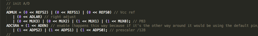
TxRx.45
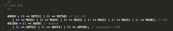
TxRx.44
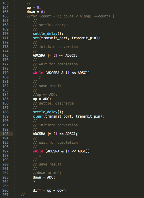
Through this process, I also rid of the serial port section, as this code sends the data being imported to a program in python. That is clearly not something that I need for my progam. Additionally, I got rid of the for loop which adds cummulatively to the values of up and down. This will help in manipulating what I need from the variable I have introduced diff = up - down.
Some notes to keep in mind regarding code that will be useful for me down the line:
setthedelay() : time given to charge the capacitor
ADMUX : tells you which setting to use for the bits
REFS2:0 : determines the power source to be used for this conversion. We are using VCC, and thus
ADLAR : left adjust (value of 1) or right adjust (default and value of 0)--this tells you which way to begin reading, beginning from the left or the right. Important to note, that in the Tiny45 this exists within ADMUX. Within the ATtiny44, this exists within ADSCRB, so won't be something I have to address in my code. Setting within the 45 was default anyways.
ADEN : found in ADCSRA, and determines when the ADC conversion occurs. When the bit reads 0, conversion is disabled. Otherwise, when is set to 1, this feature is enabled.
ADPS2:0 : this determines the prescalar, the division. This generates frequency starting conversion at fixed intervals. 128 is the most you can slow teh clock down, and you want to do this because you want to slow the conversion down to get more inputs converted before the function related to the output is downe.
RGB LED
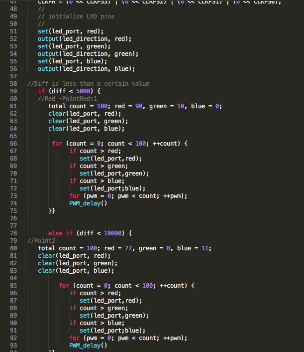
Gradient Lighting : Since a chess board is an 8x8 structure, I will have 8 main outputs from my RGB. I worked with Rob Hart to unpack thinking about these logic statements using if and else if staetments, and possibilities of connecting this to the step response. Currently, what I will need to change within this code, are the values used for " diff"
 <
<
Step Response and RGB
In this particular bout of code, I connected my input and output. In the nature of spiral development, before I go forward and program in the gradients of color, I will use full colors of red, blue and green to test what values I should use in programming what to do in response to varible diff .
Asynchronous Serial Bus Communication
Through serial communication, I will use much of what Neil has used. In this iteration, it will be enough to just recognize my 8 boards: 1 Bridge, and 7 nodes. I will be working on modifying the code based on the microcontrollers. Perhaps the best use of doing this is to connect these boards in a way that to recognize if the circuitry of the boards are working as well as powering them through one main connector of the Bridge board.
My goal for the boards as it relates to serial bus communication, is for each board 1. To send recognition of their existence 2. Enter 3. Send value of the last diff (which in this later iteration could be used in a different way, but for now just to keep track in an external space) 4. Enter.
Some notes to keep in mind regarding code that will be useful for me down the line:
#include :refer to the libraries that the code is calling upon.
get char : to recieve information
put char : to send some information out
put string : to put out a string of characters
flash : function to flash the LED once
node_id # : each of the node boards will hold the same code, the only thing being different is this node id. A means to keeping track of board's identity.
Baud Rate: Bits per second. 9600 bps is "standard". The higher, the faster the data is sent and recieved.
Parity: Low level error checking
Start | Data (chunk) | Parity | Stop : Frame of the information sent
1 | 5-9 | 0-1 | 1-2| : Bit size within the frame of information.
Through All of That...
So with all of that, I was able to develop a series of iterations of code that build upon each other.
1. hello.txrxrgb.44.c : Step Response TxRx with basic RGB functions using defined diff variable
2. rgbgradient.44.c : Main that focuses on the specific function of RGB through the gradient of color in eight defined spaces. Of course, down the line, I need to define the eight diff threshold values to determine color.
3. hello.txrxRGBbus.44.c | hello.txrxRGBnode.44.c : Combines the serial communication for the bridge | node with hello.txrxrgb.44.c
4. NEXT : To develop an updated hello.txrxRGBbus.c | hello.txrxRGBnode.c that includes rgbgradient.44.c specifics.
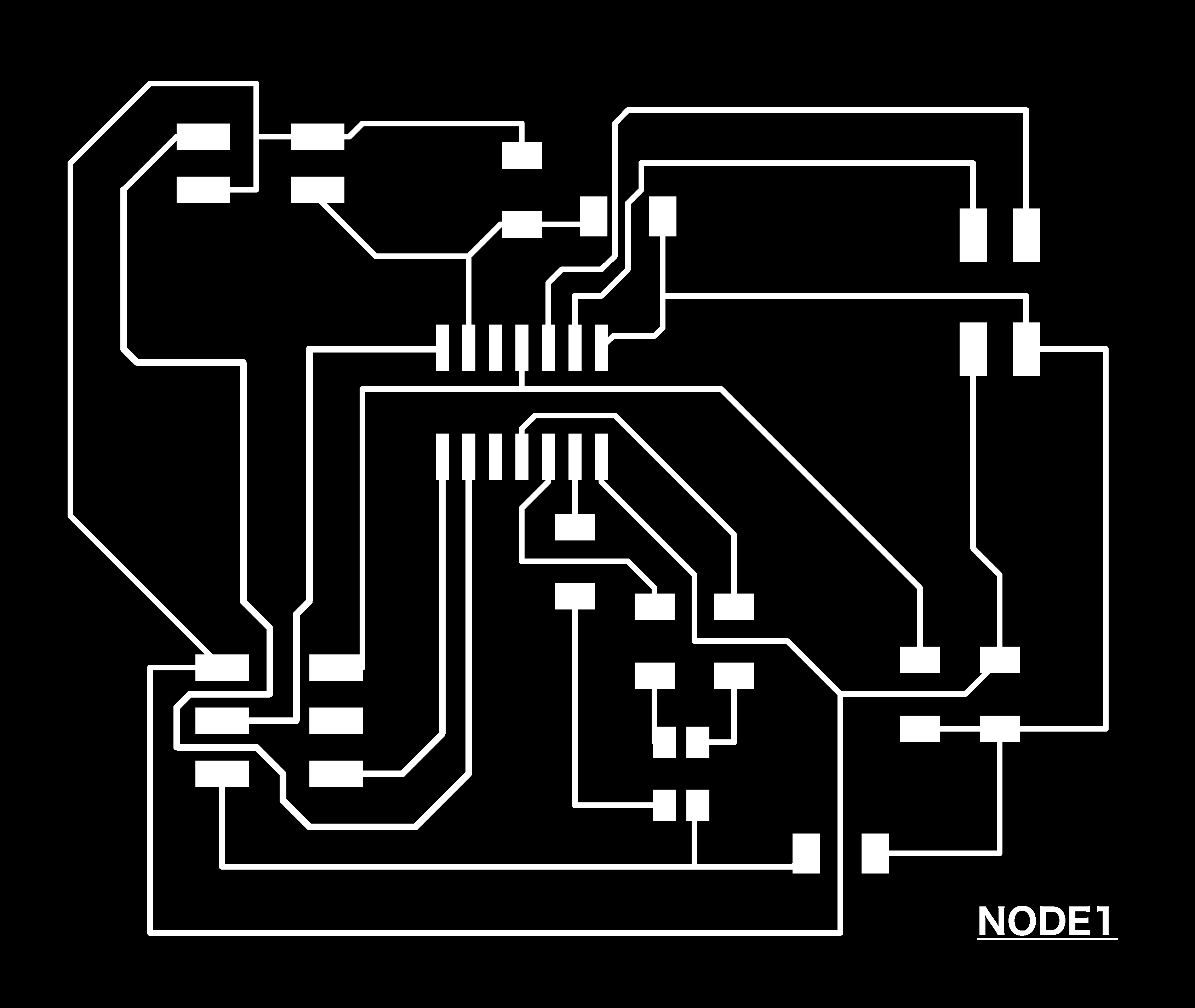
Design -- Did I Fail?
So, after feeling relatively successful in this above unpacking, I felt better about going into this process of designing behind my paper schematics.
I went through the step by step process on Eagle, drawing nets, labeling them and connecting them. When it came to draw my traces and connect my components, I was able to focus much more on what my board was supposed to look like, rather than being lazy and assuming the software would read my mind and connect things together in the way I had on my paper. Overall, drawing the schematic out first on a sheet of paper, labeling it with the appropriate pins, etc. was super helpful. I even caught that I mislabelled my TISO and TOSI pins, by checking my traces using the show A6 command, which of course, I would not ever really pick up otherwise. Who knows how many mistakes of this nature I have made in the past and pushed me into spaces of unwanted misery.
Who knew that dedicating time to these foundational steps would be so important? Ha!