Final Project
The initial though was to create an alarm clock that will wake up in a non-intrusive way
And one that will not require adjusting to tell time.
The first step was to try and fetch time online.
The ESP8266 wifi chip was very useful
Looking at Yuval Gonczarowski’s improvement of Neil’s hello world board, included an extra button setting the ship into flash mode
I have tried to make the board. That follows Yuval’s instruction. However after many trails it ended in failure.
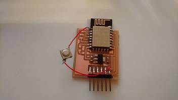
The result was me trying to attach a button with rudimentary methods
However, after many trails, it still have failed to be useable
Kevin Jiang whom used the esp8266 extensively then told me about the development boards and breakout boards
Of which with great surprise was found in the lab
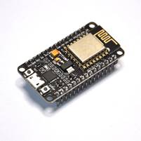
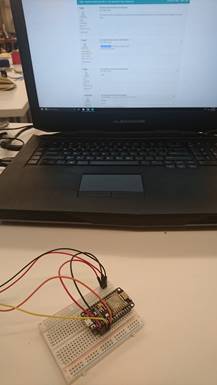
The nodemcu amica was a development board that allowed auto reflash with Node MCU without the need to press
It also has pins for easy access with a bread board
Using the Arduino IDE, it was easy to flash the esp8266
The settings as follow
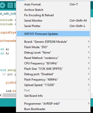
This board made everything much easier
Now onto looking on how to grab time from the web
Searching online I have encountered one that helps sets up the frame work for it
This one using the Arduino library was much easier for an entry level person like me to understand
However, the script that was provide had two major things that was incompatible with my purposes
I have learnt that the sever that I was to use to request time from will only receive requests every 4 seconds
And even so, the request will sometime fail and return an error
Hence I have remade the code so that it will
a. Request for time every 7 seconds
b. Make up for the time to display when the server does not respond
c. Make up for the time to display if the server returns error
------------------------------------------------------
------------------------------------------------
Kevin has also suggested me to use my phone’s wifi hotspot for stability issues which was very great advice
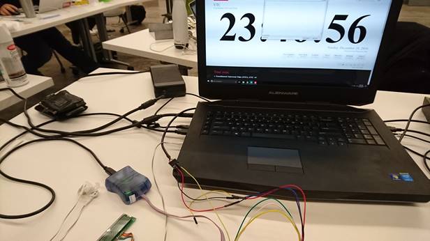
After seeing the results I wanted on the serial port with the serial monitor and the coolterm
The clock ticks every second without problem,
This can be checked with a online UTC clock
I have moved on to look at the LCD display.
Originally trying to display time with Nexie Tubes and have already brought a few
It turned out to be not a great idea as it involves high voltages DC current
Being not so skilled, I would save the parts for a later day
Hence a LCD display was chosen instead
Having looking at Neil’s hello word board, I have made one to see how it works
After some research, the lcd screen should be soldered as follow
I was able to make it display the hello world message however it seems to be not so easy to figure out how to make it connect with the ESP 8266
Hence I have again turned to Arduino IDE for help
The library that the IDE provides is easy to figure out
With the AIDE I tired to flash a programme onto the at44
However, for some reason, it keep giving me errors, hence I have chosen to export a HEX file from AIDE and flash it onto the chip with atmel studio
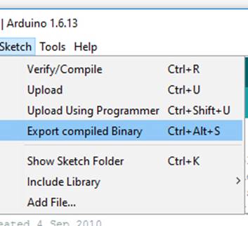
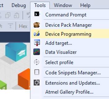
Which proved to be a success
However one odd thing is that, although with the external crystal that was present on the board, to programme it, I would have to set the clock to 1mHz
It took me forever to figure this out
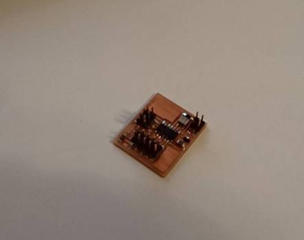
Hence, I then tried to modify neil’s hello world board to have a input and output pin
I have added headers and rerouted it as follows

It now contains an extra header while another header can serve as power input
The at44 however didn’t come with a serial input
Hence I had to figure out how to have a serial input and output, one to take messages from the ESP8266 and one to debug
Luckily AIDE provides a library for Software serial and it worked
One down side is that this library requires a large amount of bytes
Taking up a lot of space in the chip
Having it able to read the ESP
The biggest challenge here is to have it display. Little did I know, this will become to most time consuming and challenging part of the project
Many hours. 20+ was trying to get the rate of display and the rate of signals received in sync. Till now I still don’t really understand why and how it failed
I believe the trick was to have the delay rate of at44 trying to read the incoming signals in sync with the rate that it was receiving it, and then have it display the received bytes
This process is incredibly frustrating
Another thing was that the software serial was only about to send out 8 bytes at a time, and hence it can only send up to the number 255
I had to work my way around that by making use of a serial event, knowing that no time number will exceeded 60. I have se 97 as the ending signal
When the at44 receives 98 it will then know to move on to the next round of incoming serial
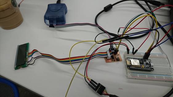
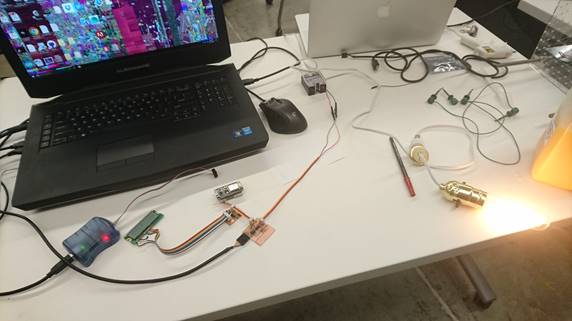
With a bread board, it is much easier to debug and to have instant response in changes I have made
------------------------------------------------------
------------------------------------------------
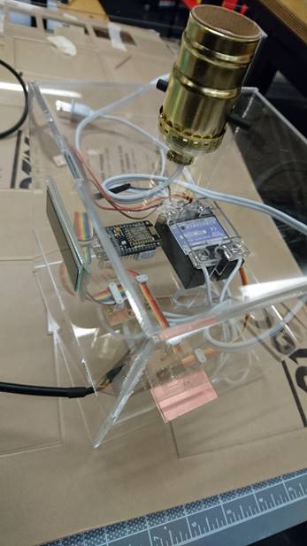
With the display and time down, I went and made the device that will serve as the waking up factor
With a previous idea of a dimmed light bulb, I have tried to continue on that and substitute a traditional alarm sound with light
With the optoisolator, it was able to control the light bulb which was connected to mains
It was interesting to have some
experience with controlling devices that are connected to mains
Here are the files

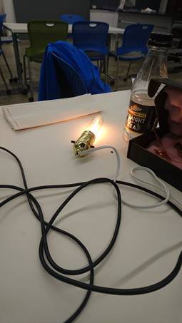
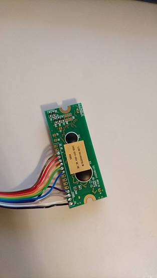
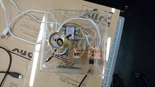
I have made the following board and have added a capacitive sensing ability to control the light
Due to time and complexity, I have failed to make an interactive alarm setting function
The light now responds to touch and will set off to slowly get brighter over a certain pre-set time and after a certain pre-set time
By varying the on and off frequency though time, the bulb will slowly light up in brightness
while a time counter will delay the initiation of the light being activated
With the delay in activating the light and it actually being light up, it is hard to tell if the bulb will light up or not
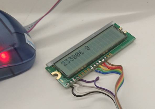
Hence, I have gone back to the LCD screen to see if I can display the state of the light on the screen
The capacitive and light dimming board will send a signal to the LCD and display it as on or off
------------------------------------------------------
------------------------------------------------
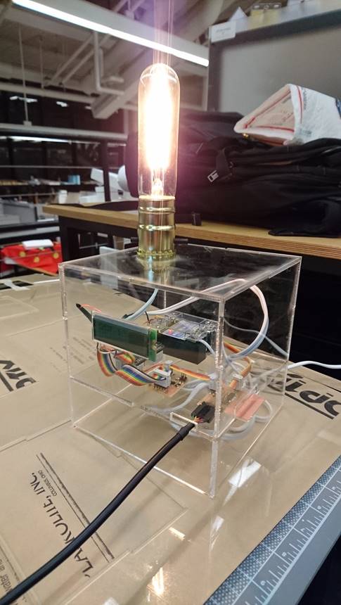
Hence I moved on to house the elements in a nice compartment
Using 1/8 acrylic the idea is to house it in a cube that displays it multitude of things that integrates into this one product
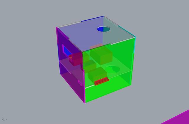
I have tired to use different joints that will seem to fit together easier for the sake to ease of making
So that I don’t have to go around and keep adjusting the angles of the pieces
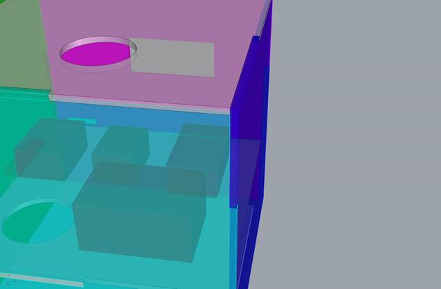
The box is laser cutted
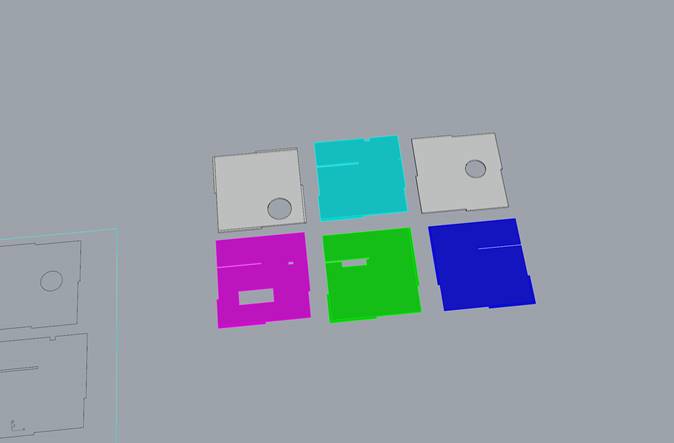
The box is then glued together and houses all the elements inside it
To answer questions
what materials and components were used?
The pcb are from the milling machine at the lab
So are the components
Opto-isolator was from the lab
And the light build and compartment was store brought
Acrylic was store brought
how much did they cost?
The light bulb and compartment are around 20 dolalrs
The acrylic sheets are 20 dollars each I have used 2
what processes were used?
Used software rhino, eagle, Arduino, atmelstudio, photoshop, illustrator, coolterm
how was it evaluated?
Its not complex, a small fist step
what are the implications?
I now can make more complex things afterwards
I would have loved to learn more low level C coding. But however, with the very limited support online and in school it is very hard to troubleshoot on my own
Hence I find that the Arduino library and community was very helpful
It was a choice that I had to make. I did try very much to try to stick to low level C scripting but to no avail
THE END