Ride on Top KIBO
What does it do?
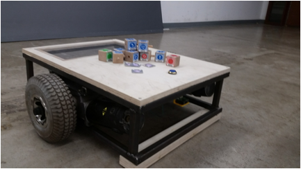
My final project is to build a ride-able version of the KIBO robot. A comparison between playing with this robot and the original KIBO will be the focus of my Master’s thesis in the Child Studies and Human Development at Tufts.
My robot reads CHIRP (a tangible programming language) blocks using a barcode scanner, stores the program, and then executes the program at the push of a button. The commands are all movement commands (e.g. forward, spin, left), as well as repeat.
Who's done what beforehand?
This is an image of the original KIBO developed by my advisor Marina Bers and a link to KIBO’s website
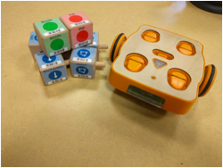
Because KIBO is now a commercially available product I was not able to get any of the design files or source code. I am using the same CHIRP blocks that KBIO uses. The only thing I copied was the design and UI
What did you design? What
parts and systems were made?
Electronics System
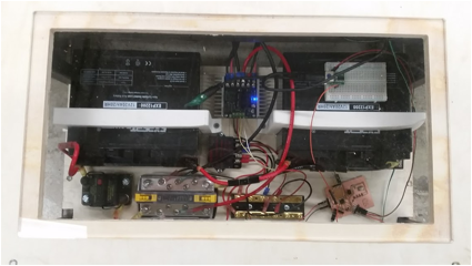
With some consultation from my friend Jon I designed this system for powering and controlling Big KIBO. It uses two 12V batteries to make 24V power. There is a 100A fuse that also acts as a power switch for now. The batteries connect to a 24V power bar that provides power to the motor controller and a 24V – 5V regulator. The motor controller receives 5V PWM signal for each motor and drives them. The 5V regulator goes to a 5V power rail which supplies the microcontroller, and the logic side of the motor controller. The microcontroller powers a PS/2 to ttl converter which is attached to a PS/2 barcode scanner. The microcontroller and converter communicate over serial as a simple network.
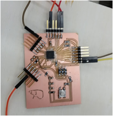
Microcontroller
During output week I designed a microcontroller board that would be versatile for prototyping this project. I had initially planned to redesign it once I had my electronics system and overall design solidified. I did not get to this especially after my first board mysteriously broke and had to remake it. Here is a link to designing the first board.
http://fab.cba.mit.edu/classes/4.140/section.Harvard/people/Vizner/Week10/Output.htm
When I remade it I thickened some of the traces. Here is the second version.
Frame
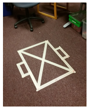
In designing a big robot for children I ran into the question of
how big is big? I started by making a tape drawing on the floor to get a sense
of scale. This one is designed to fit through the doors of the department.
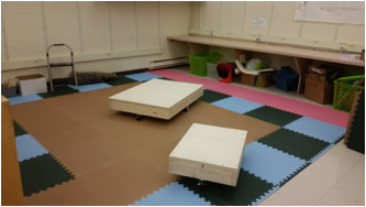
I then built
two non-powered wooden versions. I invited three first graders to
come and play with them and asked them for their thoughts. I settled on the
22”x30” version.
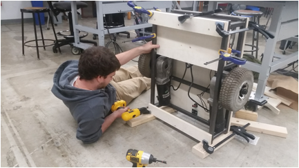
The weekend of
(11/20) I built the frame for my robot at SMFA with help from my friend Graham!
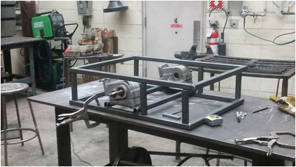
The frame is made from 1” tubular steel. The axels are mounted at
the center of the frame to allow the robot to spin in place, like the original
KIBO.
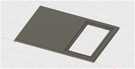
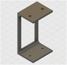
Top
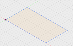
It is important for me to allow the future children who will be using this robot to be able to see the insides. I designed a top that would have an inlayed piece of clear acrylic over the electronics system so that they could look in.
I designed the top and inlay in fusion360
For part of my research I have been studying the makerspace at Malden Highschool for the last 2 years. The timing was just right that they had just had an inventables X-Carve installed. I wanted to test it out so I went over to cut the top.
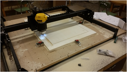
I was impressed with the machine especially at its price point ($1000). However when I later discovered that the rectangular hole I cut out was not square and had to redo the piece on the shopbot.
I originally designed the Acrylic inlay to be the exact size of the hole. I cut a test piece out of cardboard on the laser cutter and found it to be too tight. Remembering the kerf of the laser. I cut out a few more pieces of cardboard taking of a few thousandths of an in each time till I got a piece that fit nicely. I also made sure to fillet the corners to account for the ¼” bit I used to mill out the hole.
Battery
Holders
I needed to find a way to hold down my batteries to the robot. So I designed battery holders.
The holder came out a bit small but this became a feature because they are now squeezing the batteries and holding them in the perpendicular direction as well. I printed these on the makerbot.
Barcode
Holder
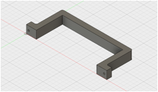
I needed a way to attach the barcode scanner to the front of the robot do I designed this barcode scanner holder.
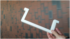
It was printed with the two tabs facing up, because this would be the orientation produced no overhang problems except for the holes. I knew that Ultimaker could handle the holes but the one in my lab in Malden wasn’t working the day I was there so I decided to try it on the Makerbot. It printed but I basically had to repunch the holes myself. Later I reprinted it on the Ultimaker with much better hole resolution.
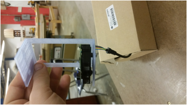
This is the makerbot print. You can see the gap between the bottom of the scanner and the plastic caused by re-punching the hole and extra plastic from the support.
Skids
The robot needed some way to slide along the floor without scratching it or tipping too much. At first I thought I might design something and try to mill it out of HDPE but there wouldn’t be enough time and it would require a lot of plastic. Daniel told me to consider furniture pads. I found the last two packs a the local hardware store. I mounted two pieces of plywood to close the gap and then stuck the furniture skids on. The robot was slipping so I removed a ¼” off of one of the plywood layers and it worked how I wanted it!
Code
I wrote a bunch of code for this project. Parts of it I’m sure could be more elegant, but hey, it works!
https://drive.google.com/open?id=0Bwn9JkDLg-21R0ZqSjIzeWt2NFk
What materials and components were used? Where did they
come from? How much did they cost?
|
Material
/ component |
Source |
Cost |
Notes |
|
Sabertooth Motor Controller |
https://www.dimensionengineering.com/products/sabertooth2x25 Hudson Ohio |
$124.99 |
|
|
ExpertPower 2 x 12V SLA batteries |
|
$74.00 |
Couldn’t find anything about the
company |
|
Steel |
Turner steel supply via SMFA store |
$30.00 |
|
|
Atmega 328p |
DigiKey / Atmel |
$2.74 |
|
|
Barcode Scanner |
Champtek Taiwan https://www.adafruit.com/products/1202 |
$69.95 |
|
|
PS/2 to TTL convereter |
Locus Engineering Ontario https://www.adafruit.com/products/1136 |
$15.95 |
|
|
Poplar Plywood 4’ x 8’ |
Home Depot |
$40.00 |
Unsure of initial source |
|
Acrylic 12”x24”x ¼” |
https://www.mcmaster.com/#acrylic/=15jvrn2 |
28.02 |
|
|
Motor Assembly |
Scrapped Invacare PowerChair |
$0.00 |
Thank you to Charlie Croteau and Eric Peloquin for
all the wheelchair parts. |
|
24-12V converter |
SINOLLC https://www.amazon.com/SINOLLC-Converter-Regulator-Regulated-Transformer/dp/B00J3MHTYG/ref=sr_1_37?ie=UTF8&qid=1482251285&sr=8-37&keywords=24v-12v+dc+to+dc+converter |
$10.95 |
Couldn’t find where SINOLLC is
located. |
What processes were used?
2D and
3D design in Fusion360
·
Top
·
Acrylic
inlay
·
Battery
holder
·
Scanner
holder
Circuit
board design in Eagle
·
Design
microcontroller board
CNC
Milling
·
Microcontroller
board
·
Top of
robot
Surface
mount PCB assembly
·
Microcontroller
board
FDM 3D
Printing
·
Battery
holder
·
Scanner
holder
Coding
in C for AVR
·
All
source code
o
PWM
output to motors
o
Serial
interface with barcode system
o
Main
program for UI
What questions were answered?
Here
is a list of questions that were either asked explicitly or emerged from the
process.
Why
does everything show up tiny in Cura and Makerbot software?
.stl files are unit-less. Both Cura and Makerbot default to mm.
That means that if you import a .stl
that was designed in inches it will read the inch values as mm values. So your
design that was 5 in becomes 5mm. Both softwares have
a scaling function. Convert one of your initial dimensions to mm and then
select uniform scaling.
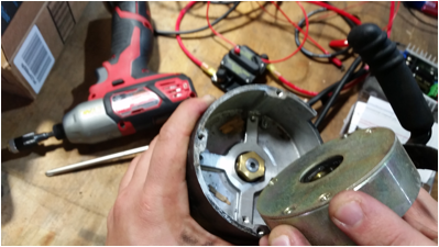
Why do
my Invacare motors lock up?
The
Invacare motors have a locking mechanism under a cover in the back. I assume
these are used to lock the wheels in place. It is a strong magnet that holds a
nut on the back of the drive shaft. I removed the whole mechanism for this
project.
Why did
my first microcontroller board break?
I
am still not sure. I drove the robot to Harvard and when I got there it stopped
working. I tried to reprogram the chip and it could not recognize the AVR. I
replaced the microcontroller thinking that I might have fried it somehow. Still no luck. I found some broken traces and repaired them.
Still did not work. The broken traces led me to believe the board was
physically damaged while moving the robot. After spending an hour trying to
debug. I realized my time (and last Atmega328p) was better spent remaking the
board.
What to
do if you break a trace trying to remove a tiny piece of solder that is stuck
to one pin?
While
attaching the 32pin Atmega328P to my new board I got a piece of solder stuck
under a pin on the corner connecting it to a trace that I had routed under the
board and out the corner. I tried for 30 min to remove it with braid but I
couldn’t get it. I accidently broke the trace that I had routed under the
board. Luckily the pin was not being used so I cut it out. I then went back to
my diagram and realized I could use a piece of wire to jump over the trace.
Crisis averted.
Which
3D printer should I use to print holes in a vertical orientation?
Ultimaker! Cura is a much better
slicing tool than Makerbot when it comes to holes
that need support to be printed.
Why
does my robot only work sometimes?
Sometimes
my robot doesn’t work… I checked all the systems and found that either the
barcode scanner or PS/2 to TTL converter are temperamental, i.e. they only send
signal sometimes. If I power cycle the robot a few times they work again. This
is not a permanent solution or permanent answer but after fighting with the
barcode scanner all semester I didn’t want to break it the week of
presentation. I plan to investigate this further.
How was it evaluated?
For
now it was evaluated by me that it has all of the
functionality that I had planned for. Next semester it will be evaluated
by children in K-2nd grade as part of my research on how the
physical scale of the objects we present young children to play and make with
can shape the way they play and learn.
Here is a video of me programming and riding it!
https://goo.gl/photos/U3WzSN7WgM1LEnxZ8
What are the implications?
Given the state of relatively low-cost and access to rapid
prototyping we can now not only imagine objects of all scales to be created for
young children but also create them! Previously a project like this would have
involved a lot more custom tooling and higher cost of development.
More on
my process can be found here:
http://fab.cba.mit.edu/classes/4.140/section.Harvard/people/Vizner/FinalProject/Progress.htm