Ride on Top KIBO
“Development is movement towards perfection, as variably
as perfection is defined”
-George Scarlett
My final project is to build a ride able version of the KIBO robot. A comparison between playing with this robot and the original KIBO will be the focus of my Master’s thesis in the Child Studies and Human Development at Tufts.
Components:
· Frame
· Shell
o Stuffing
o Skids
o “Window”
· Motor assembly
· Electronics
o Microcontroller
o Motor Controller
o Barcode Scanner
o Batteries
o Regulator and power rails
· Firmware
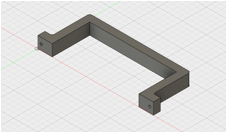
Frame
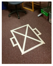
In designing a big robot for children I ran into the question of how big is big? I started by making a tape drawing on the floor to get a sense of scale. This one is designed to fit through the doors of the department.
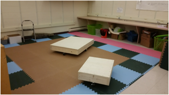
I then built two non powered wooden versions. I invited three first graders to come and play with them and asked them for their thoughts. I settled on the 22”x30” version.
This weekend (11/20) I built the frame for my robot at SMFA with help from my friend Graham!
Add hand drawings
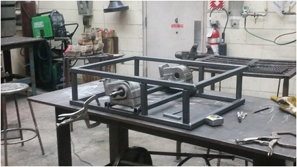
The frame is made from 1” tubular steel. The axels are mounted at the center of the frame to allow the robot to spin in place, like the original KIBO.
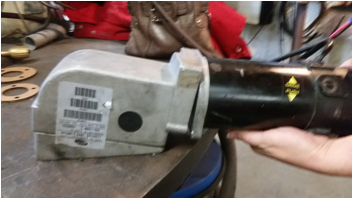
Motor Assembly:
The motors came from a power wheel chair and were given to me by a friend. They connect to a gear box to reduce the speed but maintain the high torque.
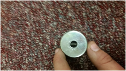
Missing interface
One motor is set up but the other is missing the interface between the motor and gearbox (not easily amazonable…) looking to source or make a replacement fast!
See my output week
page for updates on driving the motor.
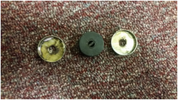
11/26:
I had spent some time thinking about how I was going to make the piece above. I thought I could model it and then make a mold and cast it out of some resin. It would not have to be the same shape just enough to cover the shaft of both parts.
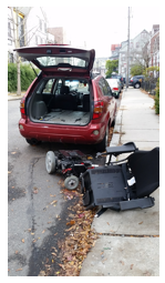
I had breakfast at my friends house. Her husband happens to sell power wheel chairs. With out mention of my problem he offered me a whole power wheel chair that he said was garbage. It was the same brand as the motors I was already using.
It was too heavy for me to carry up the stairs so I took it apart in the street and found the part I needed! I now also have an extra set of motors, wheels, gear boxes. I also have a lot of hydraulic lifts from the top of the chair. Happy to share if anyone is in need.
Micro-Controller
board
http://fab.cba.mit.edu/classes/4.140/section.Harvard/people/Vizner/Week10/Output.htm
Firmware
Upate 1:
After attaching the second motor to the gearbox I changed the program to run as slowly as possible. Here is the robots first ride around the living room!
https://goo.gl/photos/yfgYKBPtCgU2Dc3b7
PWM with counters:
https://drive.google.com/open?id=0Bwn9JkDLg-21Vm15VklhbzRRX0U
I learned how to use the counters and comparators to PWM without taking up all the processing.
Next I need to figure out how to do this with the UART.
Update 2:
After continuing to battle with the barcode scanner I realized I needed to work on the virtual machine aspect of my project. I could use my computer as the input and would later substitute the barcode scanner as the input.
Here is my code:
https://drive.google.com/drive/folders/0Bwn9JkDLg-21THR0T2ZlVHhTMHc?usp=sharing
The big KIBO can now store a list of commands including repeats.
Add video
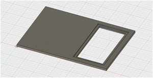
Shell
I wanted to make the electronics visible to the children so I designed the top to have a hole in it over the electronics. It has a ¾” lip to hold a ¼” piece of acrylic over it.
Stuffing:
Getting all the parts inside the robot is not trivial. Here is the processes I went through to make it all fit, be functional, and attempt to be pretty.
Battery Holder
I designed and 3D printed battery holders
The holder came out a bit small but this became a feature because they are now squeezing the batteries and holding them in the perpendicular direction as well.
The battery holder on the right is curved, something strange happened during the print but I was not there to watch it. It did not effect the function of the part so I didn’t pay much attention.
Power electronics stuffed and batteries held down with holder.
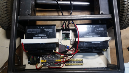
I also added quick connects to the batteries for ease of charging.
Trimming the motors
In these two videos you can see that the motors are biased, i.e. they do not spin evenly in both directions.
https://goo.gl/photos/L4Zzzb1ebEHozjKDA
Currently the speeds are set one integer above or below the zero point. That means I have no space to adjust this in software. To fix this I plan to switch the “fast PWM” mode on the other counter1 instead of counter0. From my understanding this is a 16bit counter. This will allow me more granularity in my software control and allow me to fix the problem. Back to the data sheet!!!
To do list as of
12/14
· Integrate barcode scanner
· Prepare sides and top
· Print / machine skids
· Trim motors (probably in software this means adjusting the counter for more granularity of control)
· Mount for barcode scanner
· Add big push button
· Breakout board for ttl converter
· New main board (if time allows)