Output Device
Project Description:
“Add an output device to a microcontroller board you’ve designed and program it to do something.”
I took this week to work on the motors for my final project. A programmable and ride-able robot for 4-8 year olds. Modeled after KIBO. (http://kinderlabrobotics.com/kibo/)
Microcontroller
board:
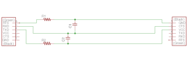
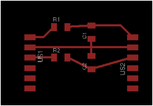
A few months ago I asked my friend Jon if he would help me build a robot for my thesis. This robot has turned into my final project and still my thesis. He had sent me a board in KiCAD and .gbr a few weeks ago but I could not read them. Instead of downloading KiCAD I took this as an opportunity to practice my Eagle skills. Using a .pdf of his schematic as a reference I made my own schematic and board in Eagle.
From this process I learned how to make a ground plate in Eagle. That is the entire surface of the board is ground. It reduces the number of traces needed. Below are my schematic and board.
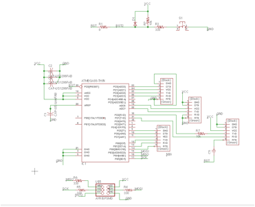
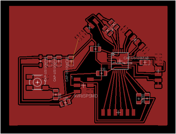
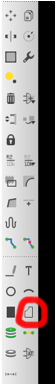
To make the ground plane use the polygon tool to draw a box around your diagram. Then type name in the command line, click your polygon, and name it GND. As you make new traces they will “disappear” in the red. To update your view use rats nest.
You may notice one open connection in my board diagram. I wasn’t sure how to best add a 0 ohm resistor to make the jump in the diagram, so I just did it on the board.
I selected the Atmega328p because it has a lot of pins which I will need if I add sensors. It has enough memory for me to store two sets of programs in the virtual machine I will build for kids to program.
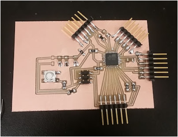
It was designed to be able to attach many inputs/outputs. I already have some ideas about how I will redesign it for final project. For now it acts as a nice platform for testing.
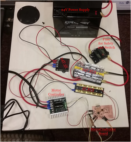
The Setup:
Programming the
board:
When I tried to upload my code to the board it gave me this error.
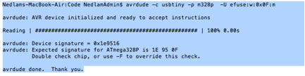
The fuses were almost what it was expecting… I tried to change them but it didn’t work.
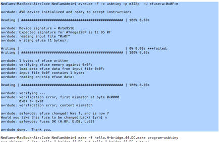
Ultimately I used the –F command in my make file and it seems to be programming my board fine…
![]()
I would be interested to learn more about what these fuses are, what they do, and how to change them.
Code:
The Sabertooth 2x25 motor controller can take PWM or Serial as inputs, I tried both, but could only get the PWM to work.
Here are my two source files. Both are modified versions of Neil’s examples.
https://drive.google.com/open?id=0Bwn9JkDLg-21WGQ1UFdVN21PV2s
I am confused about how to get the motor to switch directions. The data sheet for the motor controller says that 2.5V should give no motion any thing above is forward drive and anything below is reverse. When I make the PWM delay greater it just gets slower until it does not move at all.
Low Pass R/C filter:
When I was testing the motors on the bench it seemed to be choppy in its movement at different speeds. Looking at the data sheet I found it recommended a low pass R/C filter so I made this and it fixed the problem.
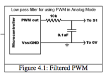
From the data sheet.
I tried to make a new component that only had 3 pins, but I made a mistake somewhere in the processes and the part disappeared… Since this was a relatively small board, and I was running out of time that day I decided to just erase the pads in photoshop.

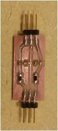
This improved the performance of the motors. I realized after I finished that I did not leave enough space for the black plastic part to rest on the board. I will re-do it soon.
Videos:
Here is one motor running in the lab!
https://goo.gl/photos/J5hmBKbg1vxKxrpm8
Newer Code waits for serial input. Drives fast or slow (slow was supposed to be reverse)
https://drive.google.com/open?id=0Bwn9JkDLg-21OVZZZW5lM2doRDg