VanGo - A Watercoloring Machine
Links to individual contributions: Marshall Kyle Darle Eghbal Keitaro Zach Soma Sam Liz Jackie Joel Kate Gary Akshata
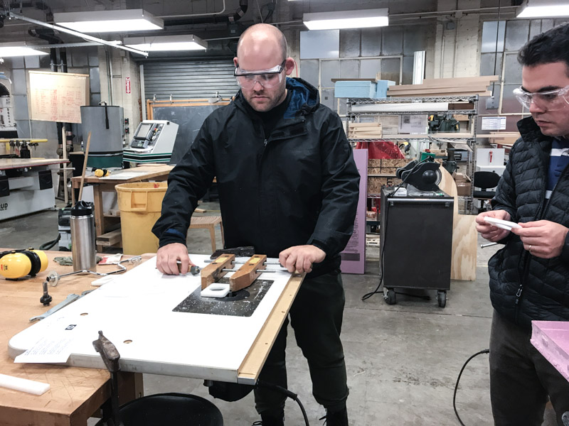
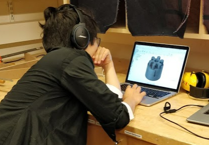
The team met on Wednesday after class to brainstorm ideas for the machine. We decided on the idea of making a watercoloring machine. The general structure and mechanical design of the machine would be a modification of Jake's design. The end effector would be capable of holding a paint brush, dipping into a paint box, and painting with multiple colors.
Here's our team structure and points of contact (POC) for each team:
Mechanical Design & Machining: Daniel (POC), Kyle, Darle, Eghbal, Keitaro
Electrical & Assembly: Zach (POC), Soma, Liz, Sam
End Effector: Jackie (POC), Joel, Kate
Software: Gary (POC), Akshata
We will now summarize the successes and challenges faced by each of the teams:
Mechanical Design & Machining Team: Daniel, Kyle, Darle, Eghbal and Keitaro
Mechanical Team: Daniel, Darle, Eghbal, Keitaro and Kyle
Design
The mechanical team took on the design and fabrication of the parts for VanGo!
Design Process
After class last Wednesday, we had an architecture section team meeting and decided to make a painting machine. The idea was to use Jake's frame and edit the parameters to a 20" x 30" bed (large standard watercolor sheet). We then split off into different groups and I joined the mechanical section which took on the design of the frame and axis, the set up of milling files and the fabrication. We started off by downloading the files linked on Jake's machine design gitlab page. We searched around in the folder and found the grasshopper files for the x-axis, y-axis, and z-axis but realized after browsing that the frame of the machine was not parametric (in terms of grasshopper constraints - Jake later explained that there is a way to use certain parameters in grasshopper, bake them and edit the model in Rhino).

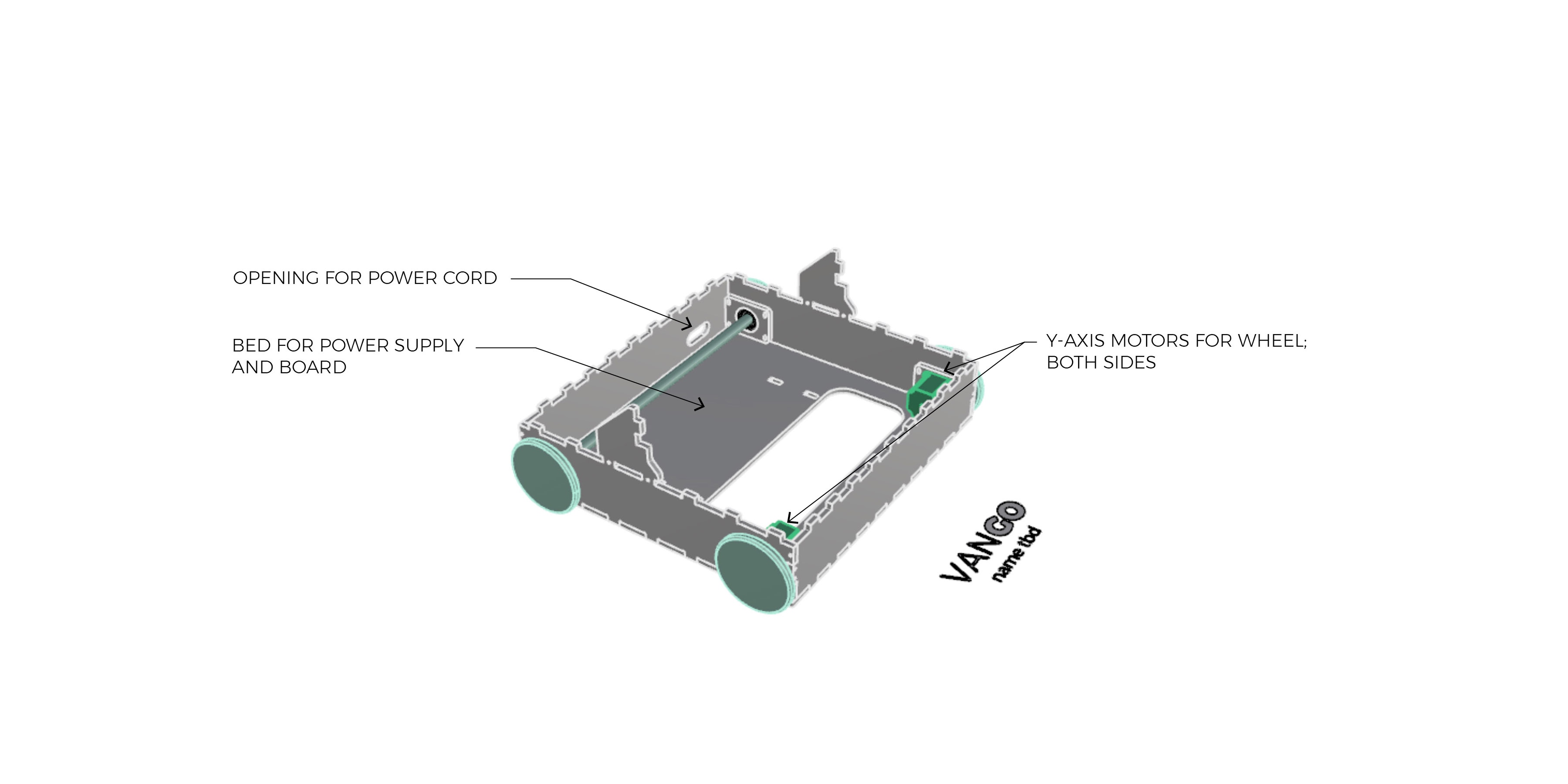
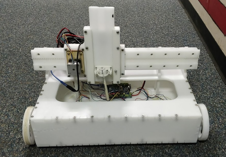
Becacuse we would be investing a noteable about of time for barely noticable changes, we decided to make the device mobile, allowing the y-axis to have an infinite length. As a team, we then proceeded to design a device on wheels which used the same y-axis motors for movement and the same x and z axis as created by Jake. The main concern for the machine was weight - weight in terms of the vertical load on the wheels and weight in terms of distribution for balance. One of the initial thoughts was to create a machine that has just two wheels to reduce the heaviness of the body. However, we felt this would cause balance issues as the machine moved. The final design contained a body for the power supply and TinyG along with a slot cut for the wiring and power supply.

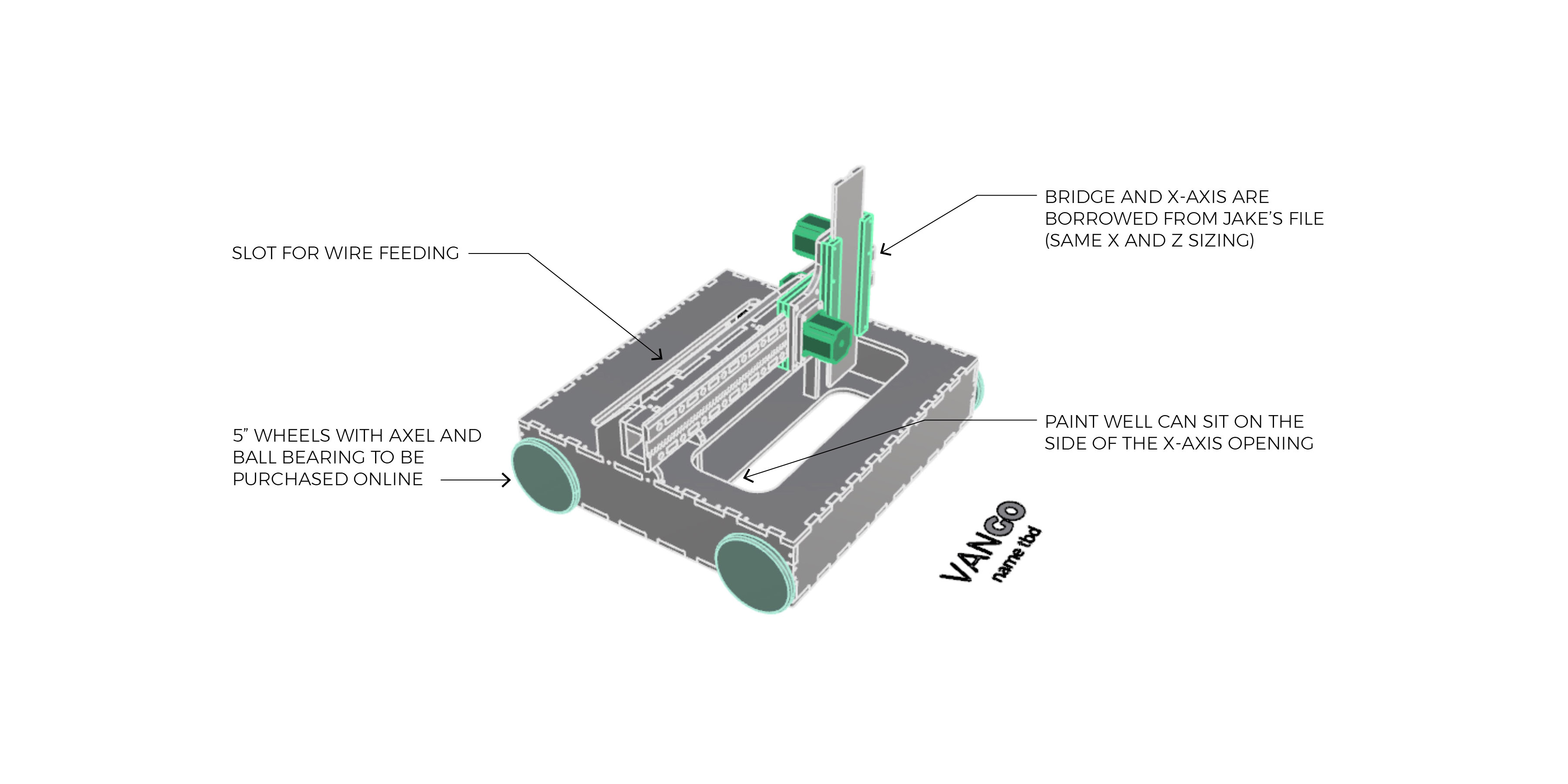
After discussing the design with Justin, there were a few suggestions that came up. One, to make the machine longer in the x direction to max out the drawing width. We trying making this change, but found that the pieces would not fit on our 4x4 sheet of HDPE. The original design with a 16" x width nearly maxed out the sheet. Two, to consider using timing belts and gears to relieve stress off of the wheel motors. This is something we really wanted to implement but could not find readily available timing belts to use. Three, to take the weekend to solidify the design and milling.
Mastercam
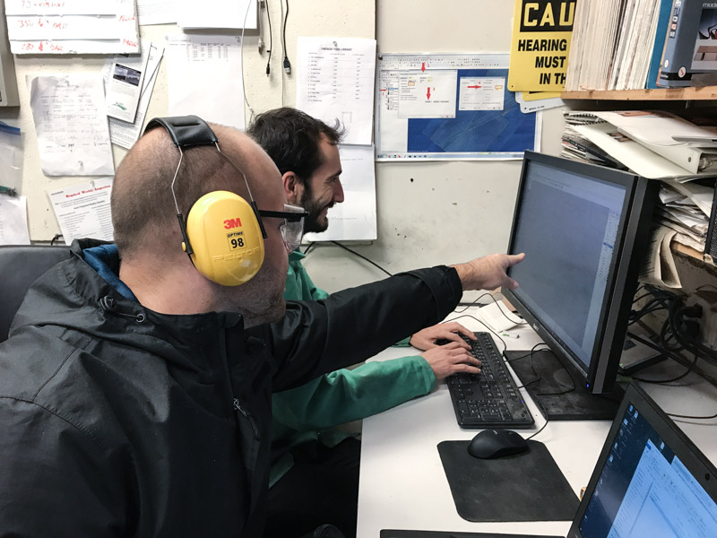
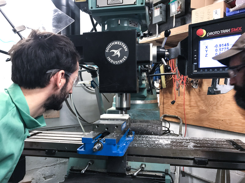
After we designed the machine, Daniel, Kyle and Keitaro set up the mastercam files and we were on to milling!
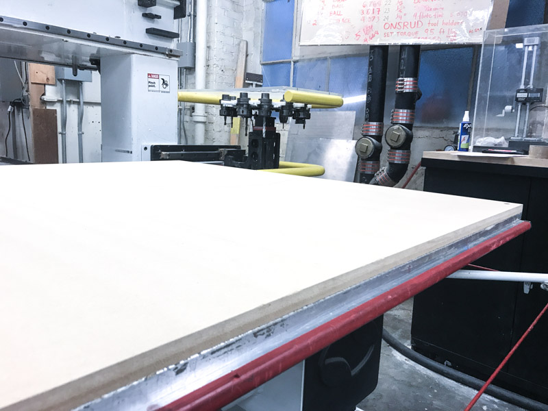
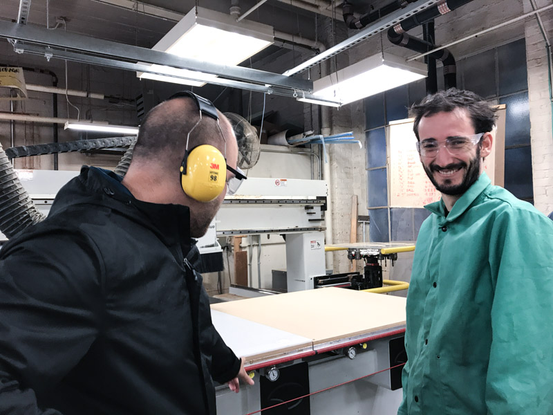
With much help from Justin, we first started by surfacing the sacrificial layer. After that was finished, we placed the HDPE on one half of the Onsurd bed.
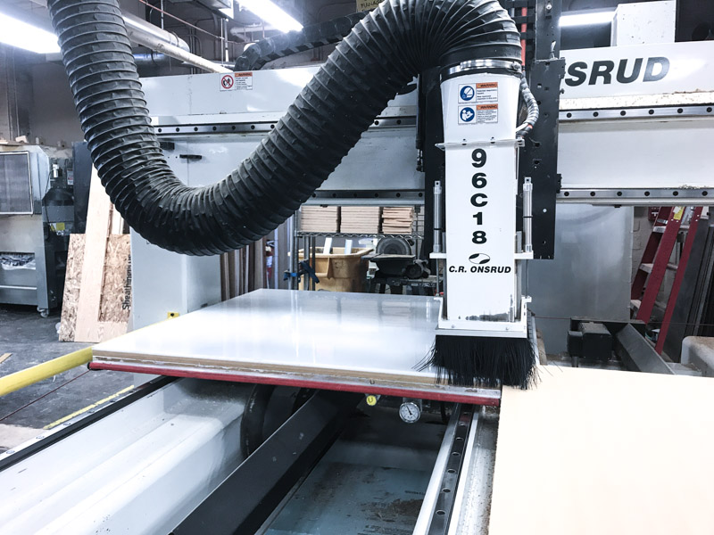
Machining
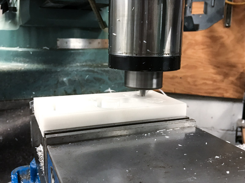
The first pass at 1/4" was a rough cut to the depth of the pinions - Justin suggested doing it this way so we would not affect the vacuum strength. If we did cut through before milling all of the pinions, this would potentially cause uneven cut depths. The next pass at 1/8" was a finish cut also to the depth of the pinions. We then did a similar rough and finish cut of the pockets, and finally did a cut pass for the outline of the parts.
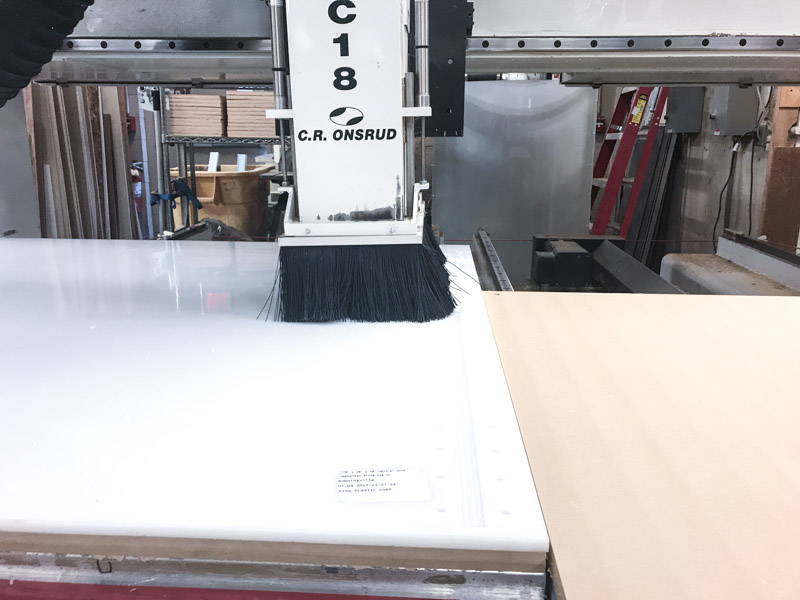
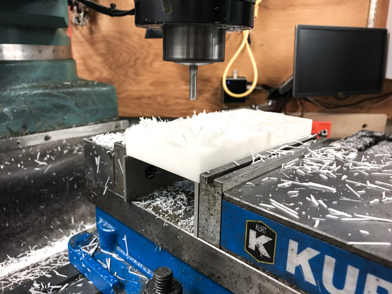
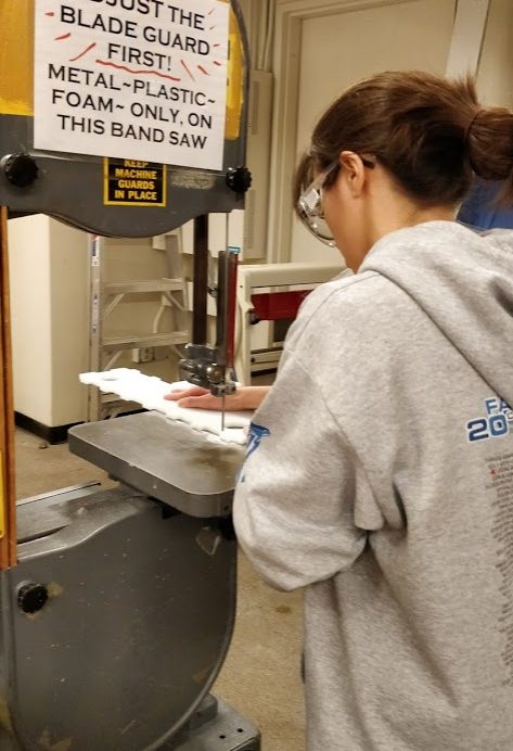
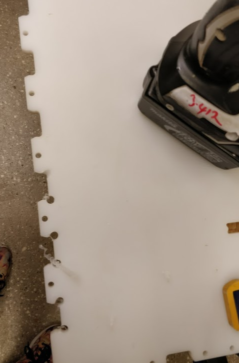
The final pass gave us several issues. First, the cut depth across the board was not even because of uplift at the corners of the material. Because of this, some of the pieces began to cut all the way through instead of having a thin layer of material to keep it in place. As a result, smaller parts because to move around and jam in the mill. Luckily, we did not have any significant damage to the parts but a handful were not cut properly.
Because the pieces did not get a finish pass and several were not cut all of the way through, we used a router to clean up the edges on some of the parts. For the smaller pieces, we used a vice to grind down the edges and inner pockets.
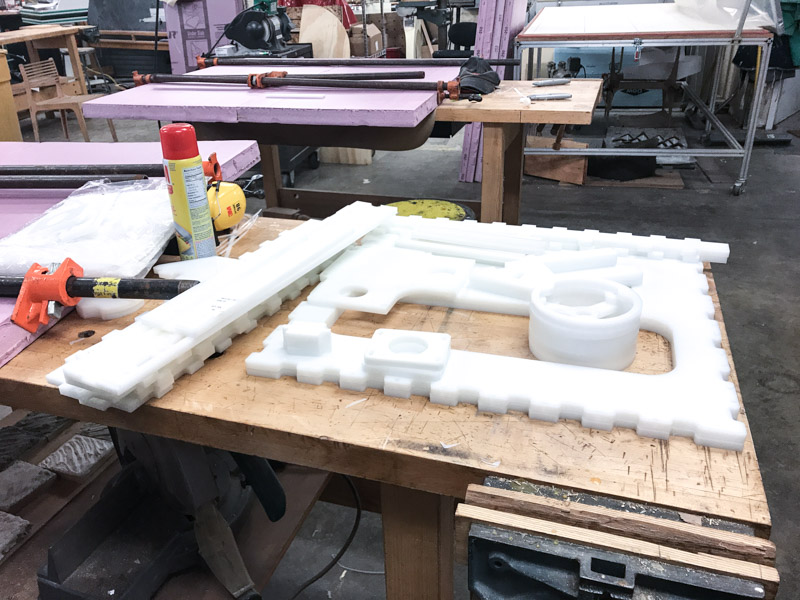
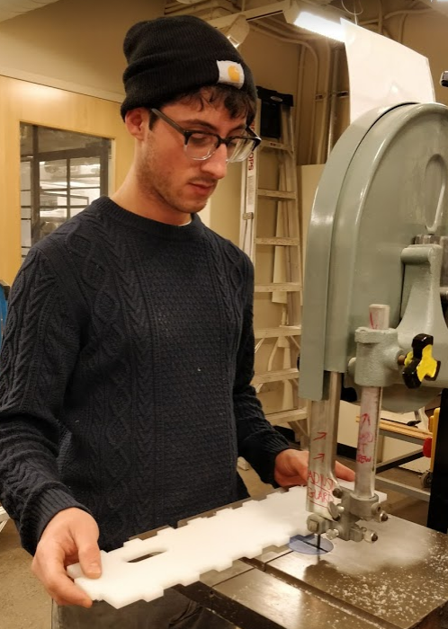
After that, we were done with the parts on the HDPE sheet and larger Delrin sheet. The next step, milling the smaller Delrin sheet, took quite a bit of time.
We milled the small delrin sheet on the ACME mill in N51. Because this required a small, 1/16" end mill, we were forced to run the job at 50% speed so as to not break the bit. This took over two hours to complete.
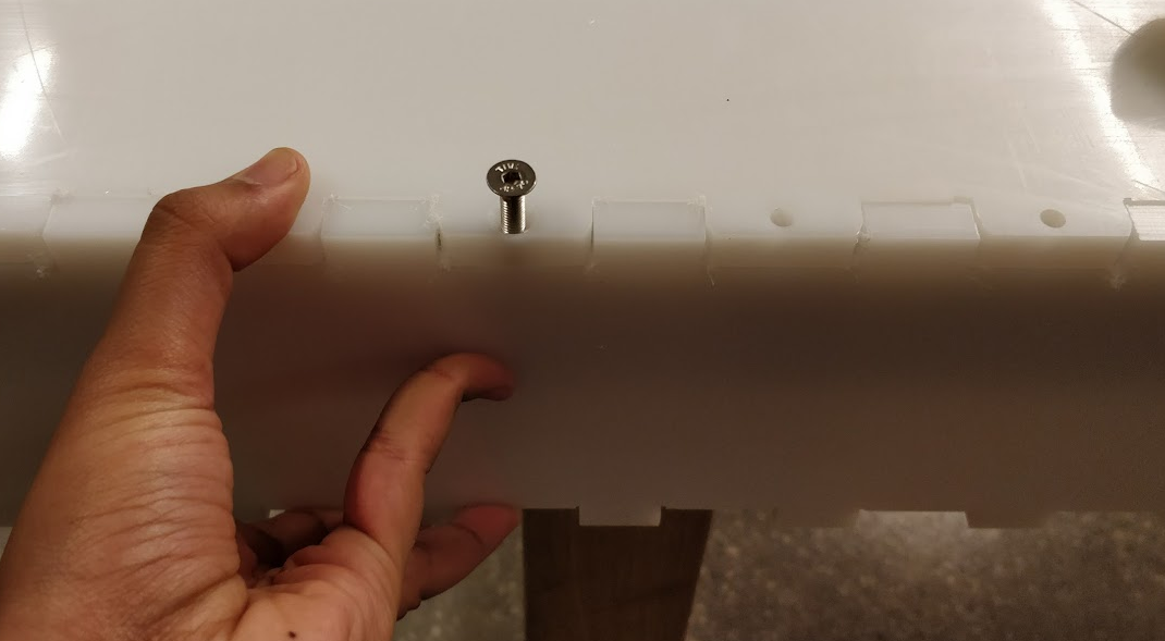
After that, our parts were finished! Or so we thought. We discovered several mistakes after handing over the parts to the assembly team. One, the pieces were not dogboned properly. The joints were copied from Jake's mill file and there was a false assumption that these connections would work once we milled. The tolerance was about 1/8th of a inch off and the assembly team was forced to manually correct the dogboned corners. Another mistake was with the parts attaching the motors to the body and axis. The pieces in Jake's file did not match the motors we were given and the assembly team recut those parts.
Other problems that we encounter were:
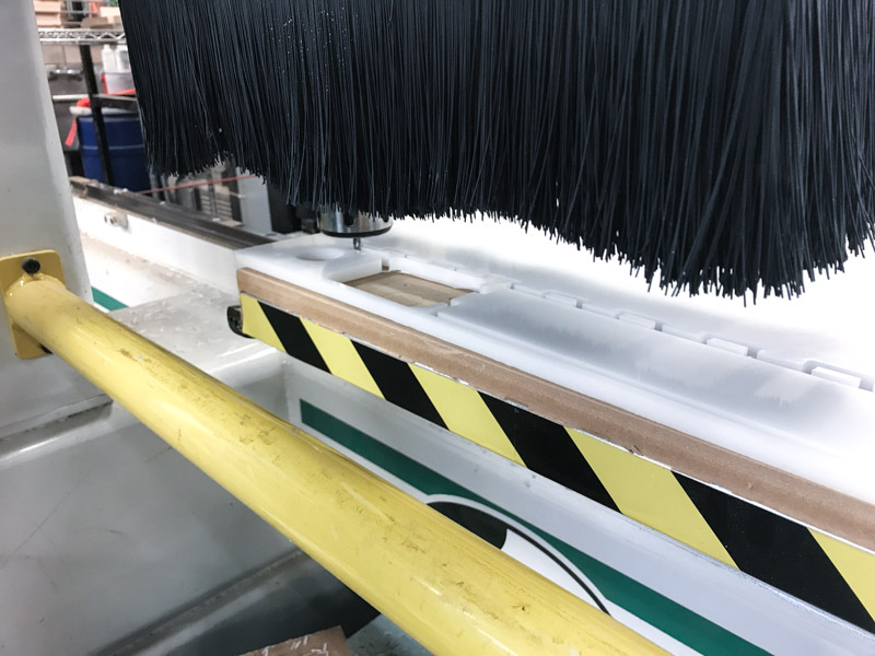
- Pieces jumping out of place: For the first cuts, we program Mastercam so the machine will cut almost to the bottom leaving a thin layer of material that would keep the pieces together and in place. When the machine started to cut the final layer, some of the smaller pieces pop-up out of place and the machine cut some of them, which made them useless. Solution: Thankfully we had enough material to cut again those pieces, but for the second time we decided to leave the thin layer and cut it manually.
- Pockets deep: To be sure that the deep of the pockets was the correct one, we decided to run first the pocket workflow. After that we measured the deep of the pockets, thankfully the cuts were correct and not further adjustments were needed. Dealignment of material in the cutting bed: While cutting one of the pieces the milling machine moved the material, this forced us to stop the process and align the material again. To do that from mastercam we selected two points or coordinates of some of the holes that had already being cutted. With that we manage to position the tool in this positions and align the material again. We also had to modify our process to only cut what was missing from our pieces and redo the pieces that the milling process damage.
Electrical & Assembly: Zach, Soma and Liz
Asssembly
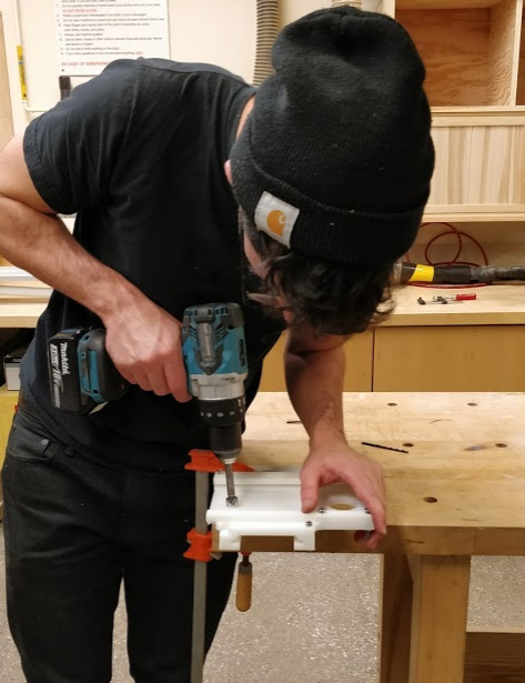
Our job began as soon as the Mechanical team was done machining. Immediately we struck upon problems. During the milling process, none of the dog bones had actually cut out so none of the press-fit connections actually worked. We had to recut all of the inside corners so the pieces could come together
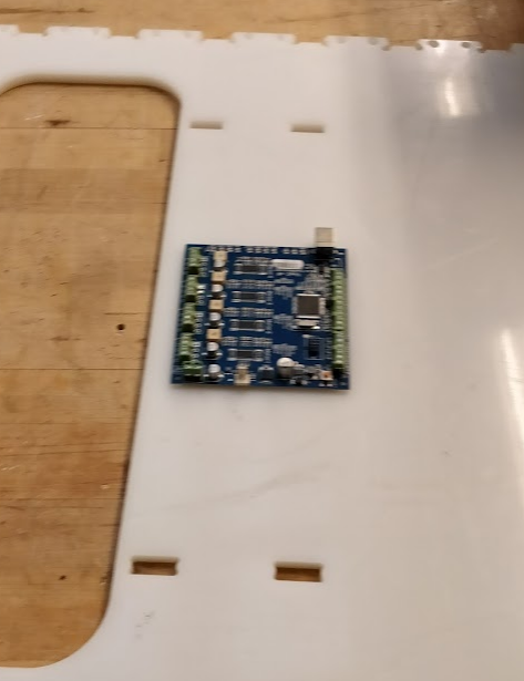
After solving our press-fit quandary, we set to fastening all of the joints together. We countersunk and screwed in fasteners and also drilled holes in for the TinyG.
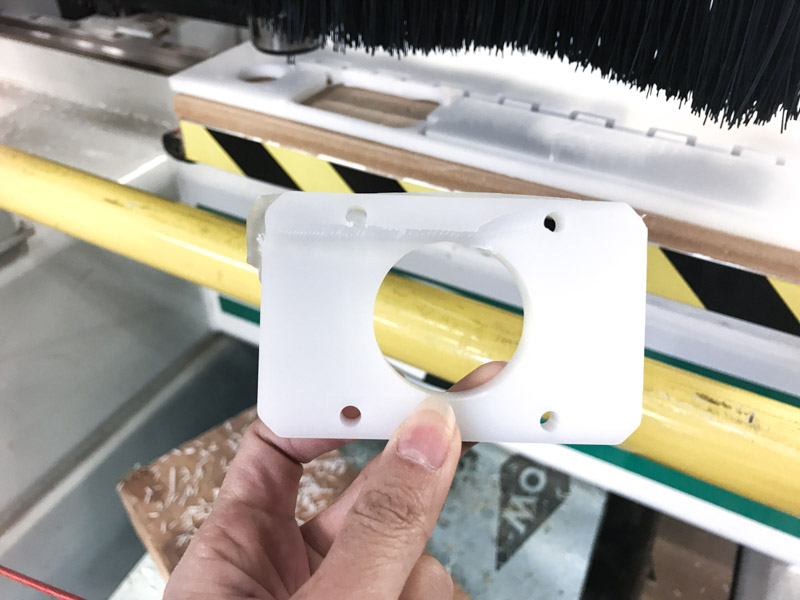
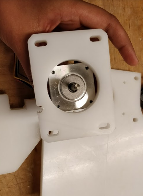
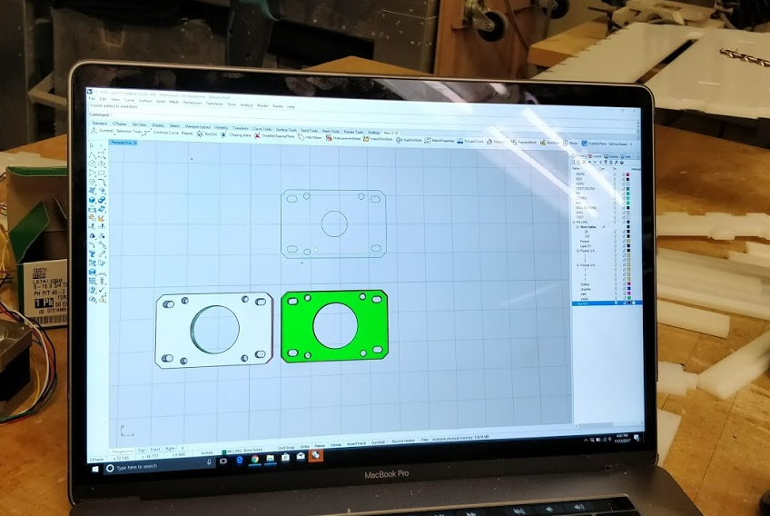
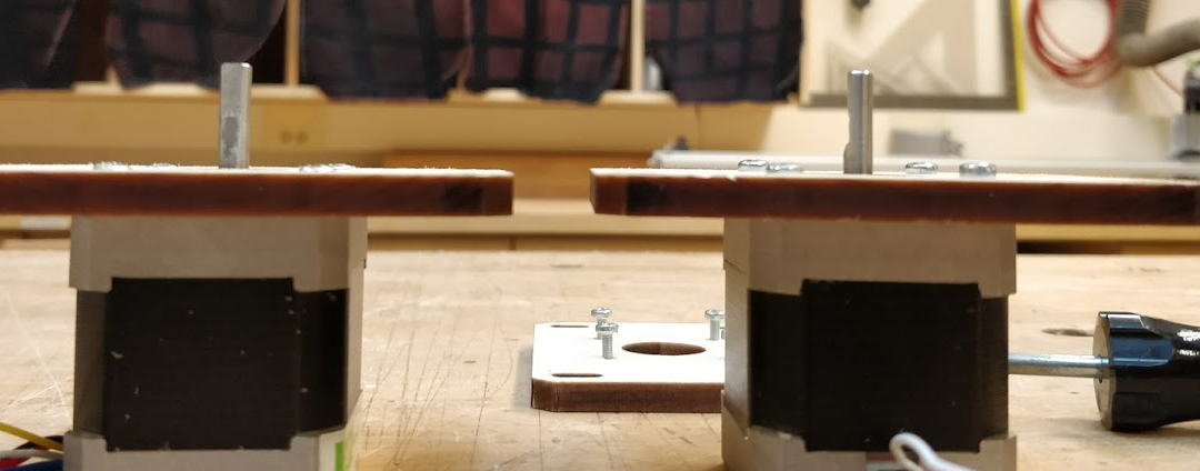
Then, when trying to attach the motors we realized a new problem. The mechanical team had used Jake's motors in his design but Jake's motors were not the same ones that we received! None of the mounts fit so we lasercut new mounts out of wood.
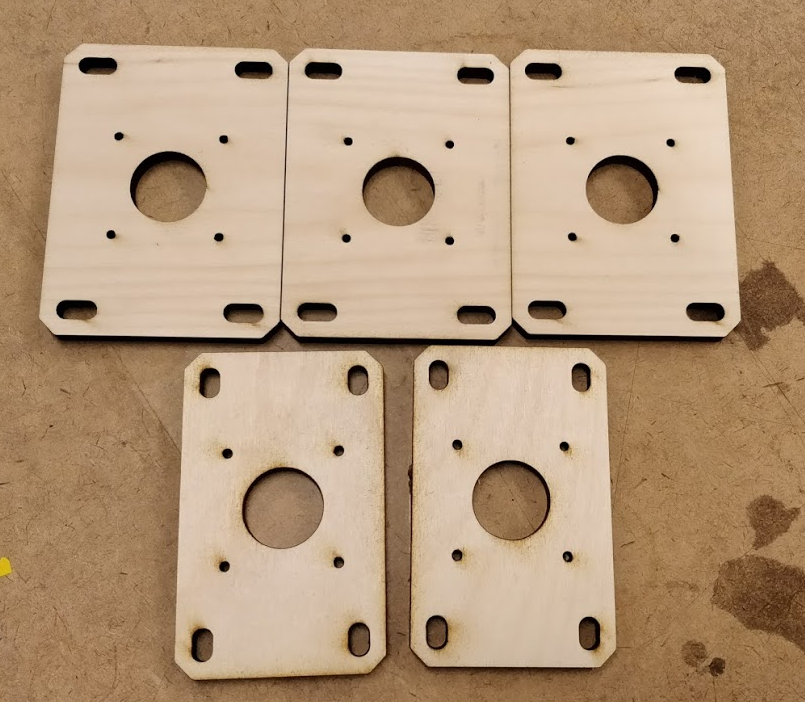
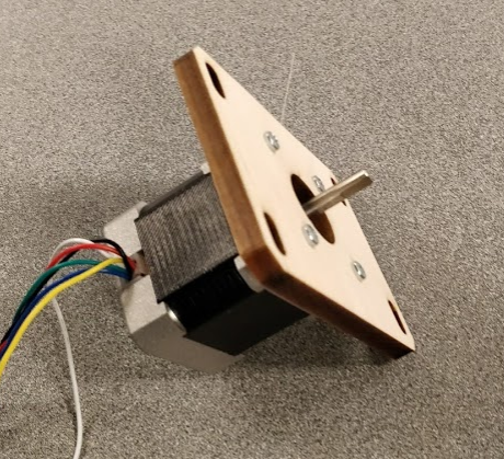
In assembling the new mounts for the stepper motors, we had to manually countersink so the mounts would sit somewhat flesh with the body of VanGo.
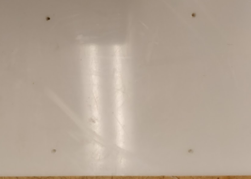
We then sanded down the parts of the rotating elements that did not fit together to continue in trying to make our Van actually Go. We attached the TinyG and built the frame of the car only to realize another issue! One of the mill jobs on our x and z axis elements put holes through the HDPE where they didn't belong so the rack fixtures did not have good attachment points. We had to redrill holes precisely to not mess with the rack mechanism but also allow for a stable rack fixture.
Our frame was finally somewhat built!
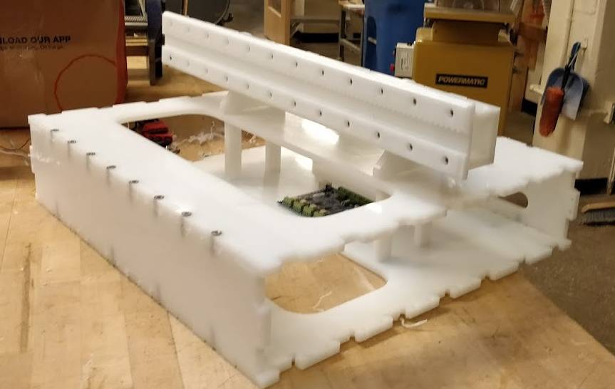
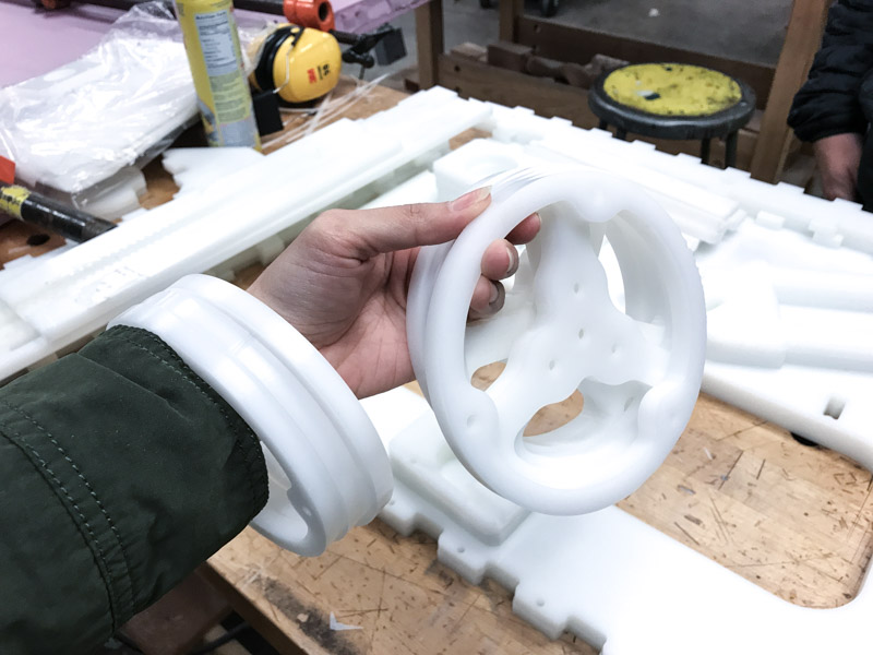
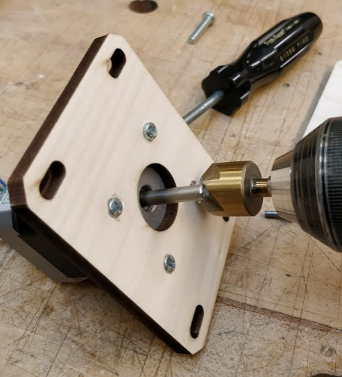
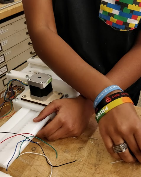
To add the side panels, we fixed our set screws onto the axles of our motors and also put our gigantic ball bearings on board. For some reason the mechanical team bought ball bearings much to large for our use and an axle that was made of plastic......
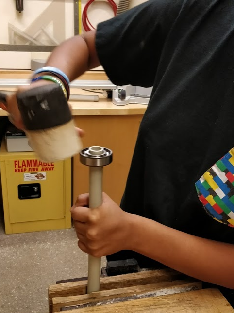
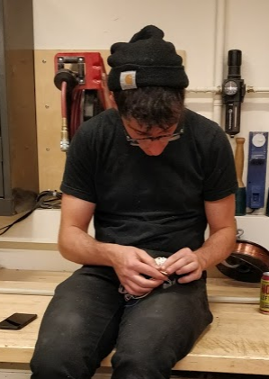
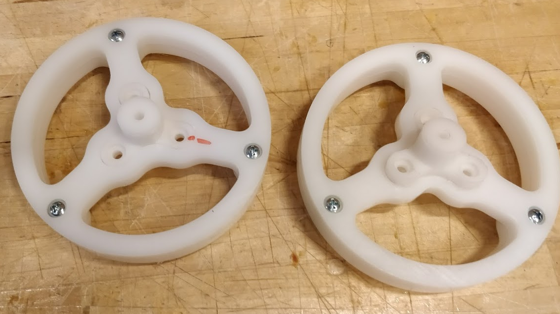
We then found we had lost one of our pinions...here's Sam trying to make us a new pinion! We ended up 3D printing a new one for the z-axis hoping it wouldn't take too much of a load.
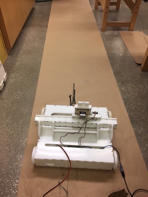
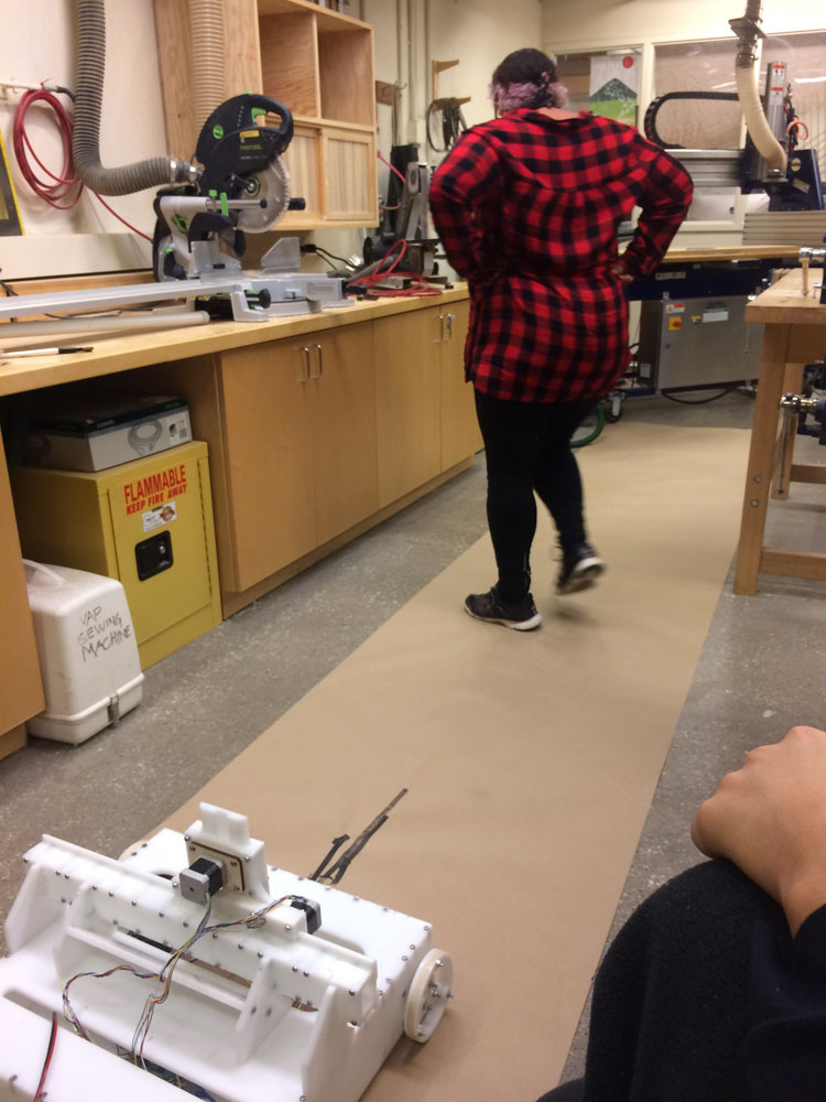
VanGo finally actually has wheels!
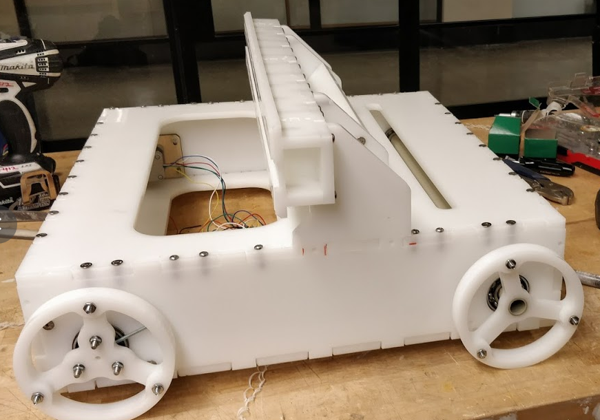
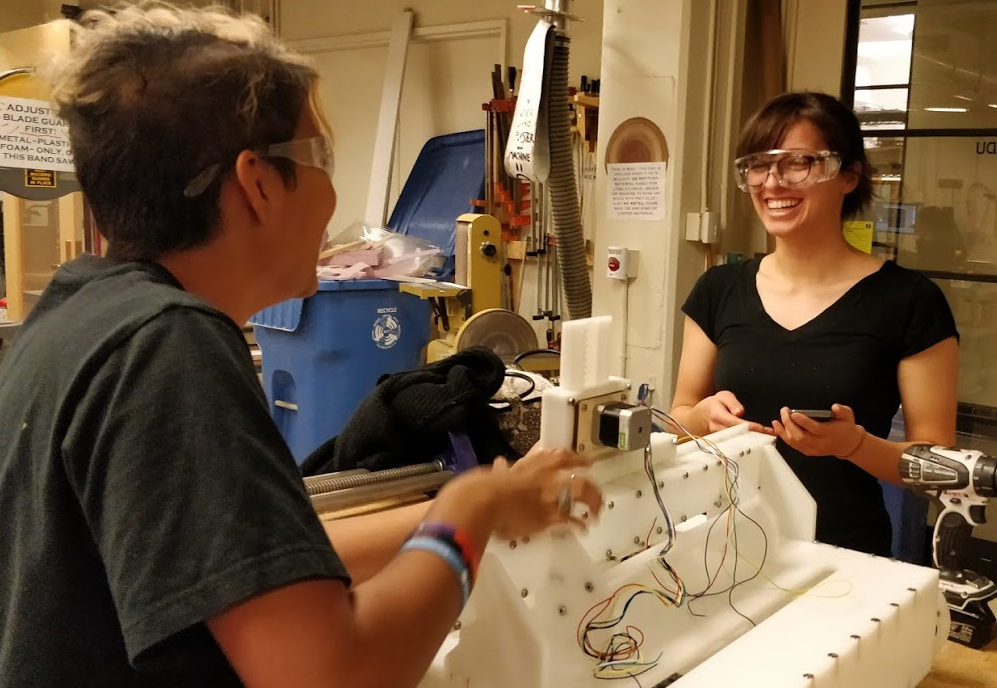
We finally finished putting the x and z axis together and here's Jackie and me very happy to finally have almost the full machine done!
Electrical
We didn't really end up doing that much of this...there wasn't enough time at the end to make the wires look super nice. It kinda looks like this right now...
End Effector Team: Jackie, Joel and Kate
Brush Holder
We wanted a paintbrush end effector to be more interesting than a simple clamp. We looked to existing painting machines for inspiration and found that several incorporated some kind of brush angle or spinning action when the paintbrush was in motion. We liked the idea of a spinning brush, but were trying to stay away from additional electronics in the end effector. Instead we considered designing for additional degrees of freedom in the brush motion and tilt angle.


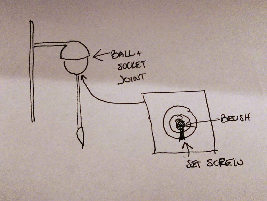
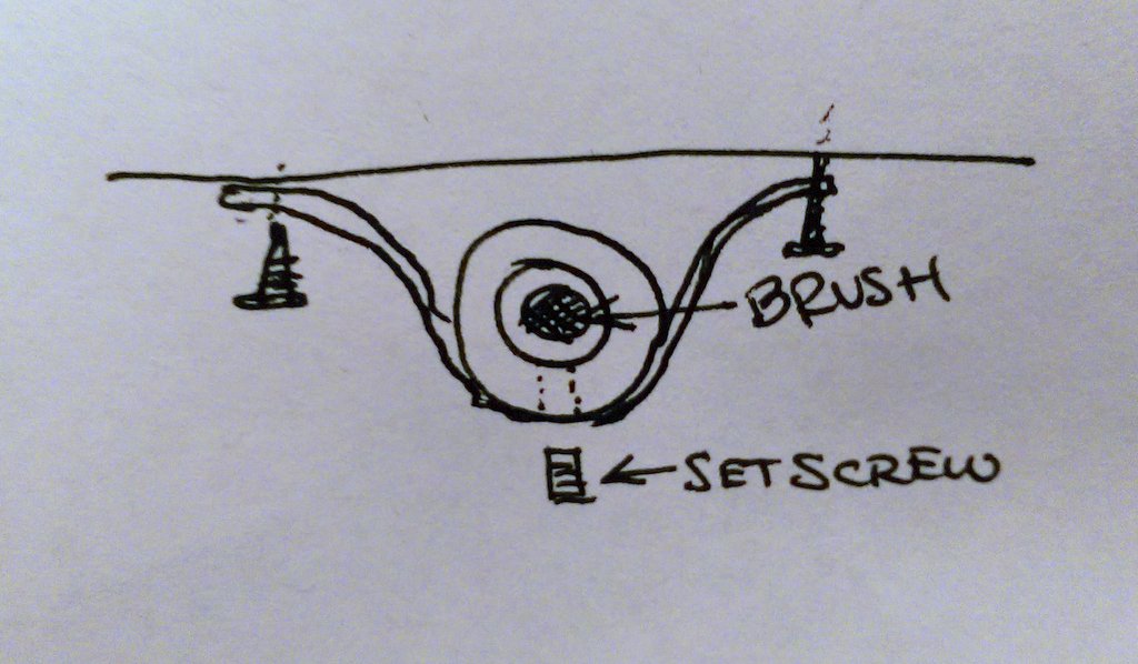
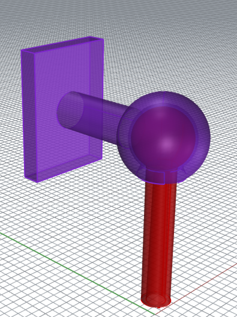
Our inital idea for freedom of motion was a ball-in-socket joint. However, fabricating a really smooth ball in socket joint was a challenge. The Dimension printer with dissolvable support does not have great resolution, so the actuation of the joint would probably not be smooth.
We considered a system that could mimic a ball in socket joint. We thought of using rubber bands to restrain the paintbrush in the x and y directions, but holding the brush in a neutral position would be very difficult. Then we considered a gimball/gyroscope system using screw or pins to allow for rotational freedom. The pins were not a very elegant solution, so we atttempted to create flexural joints with really thin material.


Paint Holder
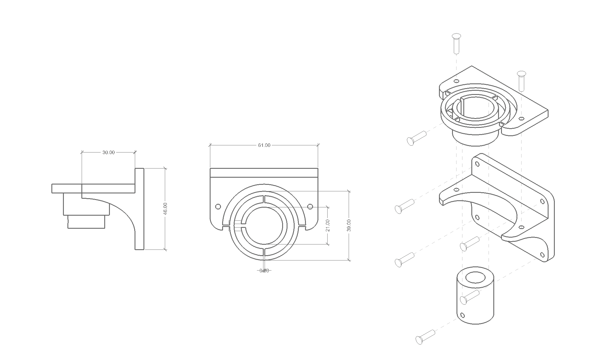
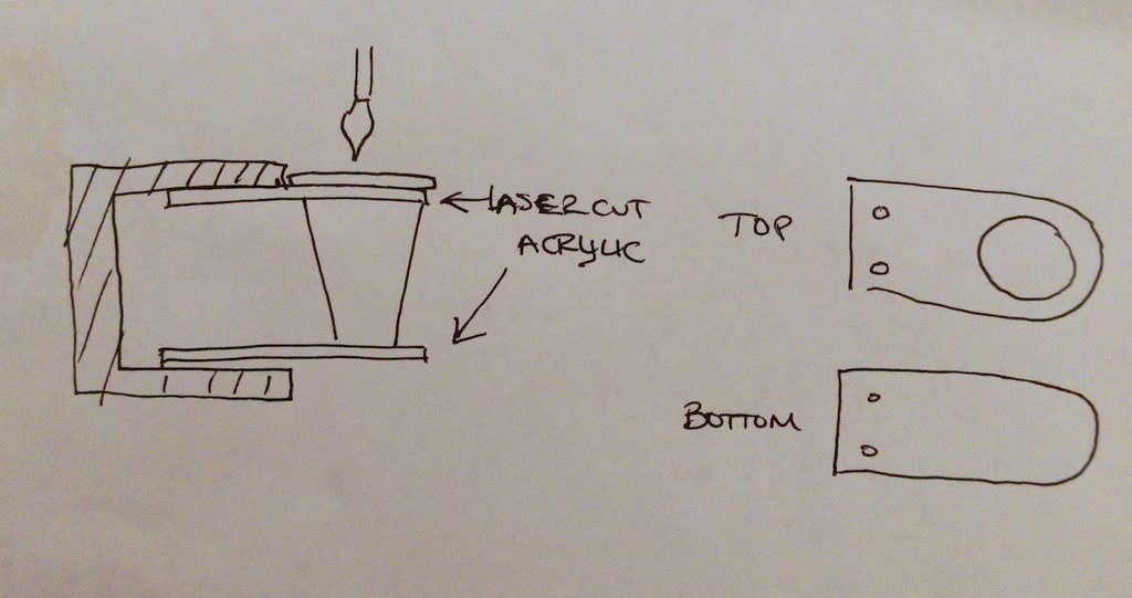
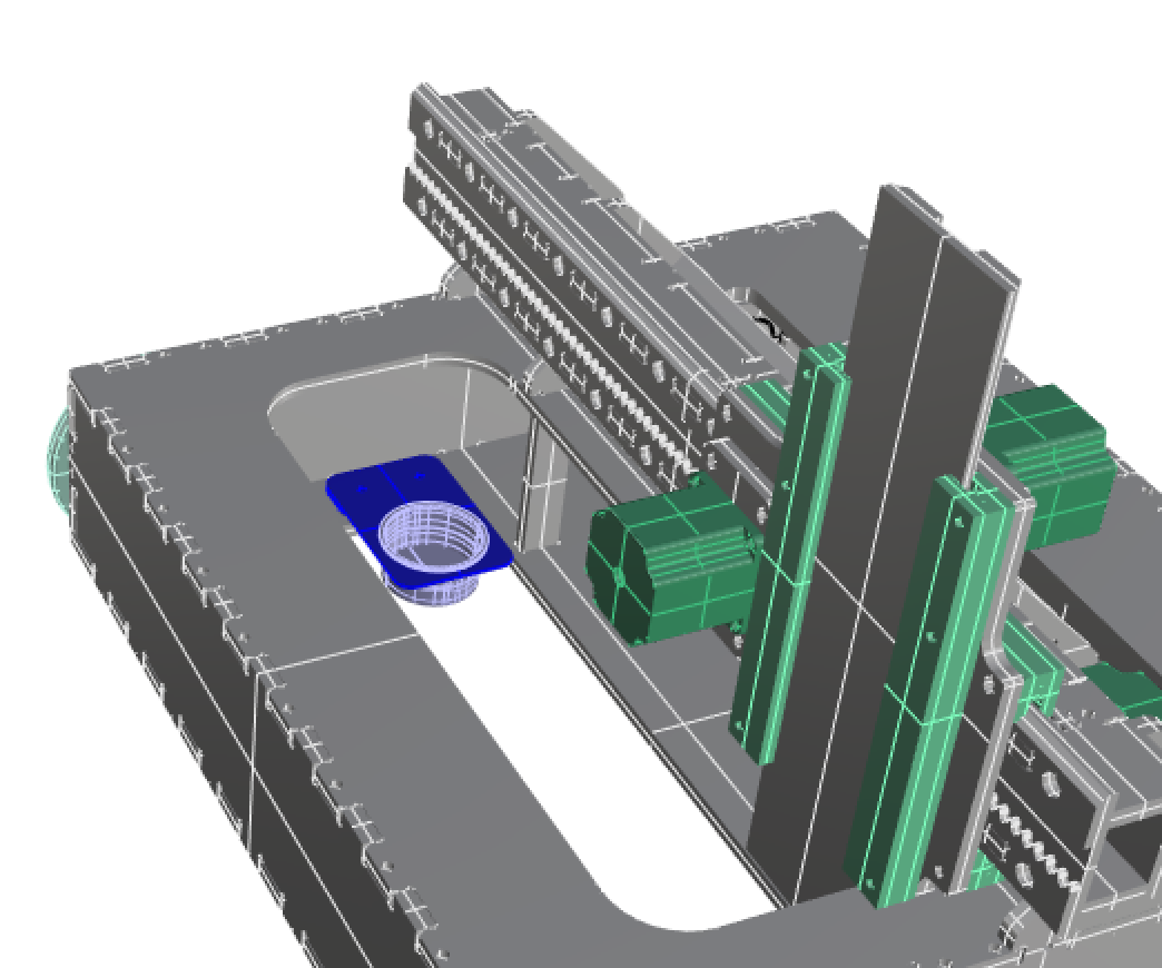
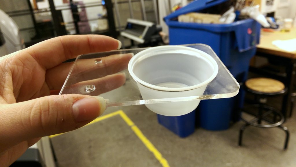
In addition to the brush we had to consider the paint. One option was to create an ink injection system, but this seemed like an excessively complicated option. Instead we considered a palate of dry watercolor paints or a single cup of liquid ink. We decided to use a single cup of liquid ink for simplicity because it would allow us to have a paint supply that attached to the machine and moved along with it. We designed and cut an acrylic cupholder that could be screwed onto the machine and would catch the lip of a standard size cup, making it easy to switch out cups to use different colors.
Software Team: Gary and Akshata
Here is the summary of the work that we did over the last week:
TinyG - Testing and Validation
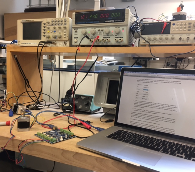
The documentation provided for TinyG was quite exhaustive which made the process of setting up and testing the TinyG a lot easier than we had thought. The first step was to connect to the power. We made sure to wire the power input correctly. For our initial tests, we used the power supply available in the arch shop, and set the voltage to 24 volts. The next step was to establish the USB connection and install the FTDI drivers for Mac. We then set up Coolterm and established a simple serial interface with the TinyG. We then wired the motors by finding the coil pairs which was fairly simple. We then proceeded to spin the motors according to the default G-code presets.
A note on G-Code. A standard block might be 'G1 F400 X300', indicating linear interpolation 'G1' which finds the straight path between the current position and the next, an 'F400' feedrate of 400mm/minute, and a movement to 300mm on the X-axis, depending on whether the movement is set to relative or absolute.
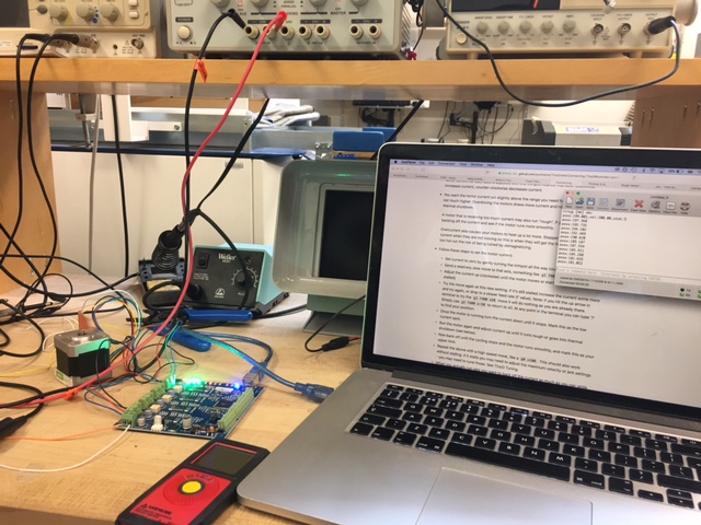
The next step was to find the limits of the stepper motor which turned out to be quite challenging. Overdriving the motor draws more current and results in overheating and thermal shutdown. So, this is a crucial step. According to the TinyG documentation, we could use the trimpots (plastic screws near each motor input) nearest to each axis to fine-tune the amount of voltage going into each motor. However, we struggled to find a point at which the trimpots affected the upper limit, while the motor itself refused to run at higher than F380 without stalling, which seemed like a relatively low speed. After some adjustments, this number fell to F250. We're not sure if this was just a connection issue, but a top speed of F600 was achieved after reconnecting one of the motors. This feed rate seemed adequate.
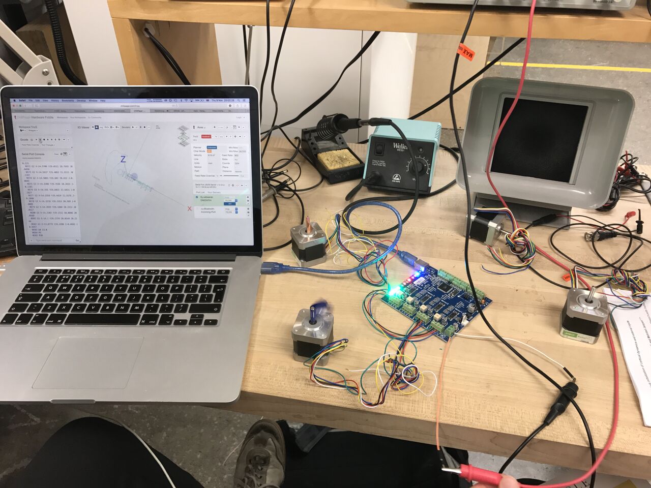
Using the TinyG JSON server and the serial port used by our TinyG board (ls /dev/ttys.*) we were able to connect the TinyG to three motors, and have it running all three axes at once.
Since we had decided to create a painting machine on wheels rather than using a rack and pinion for Y-axis movement, a number of issues need to be accounted for in the software:
The extensible Y-axis parameters (depending on the paper used, etc.)
The dipping motion of the brush coming on and off the paper: could this be given more nuanced?
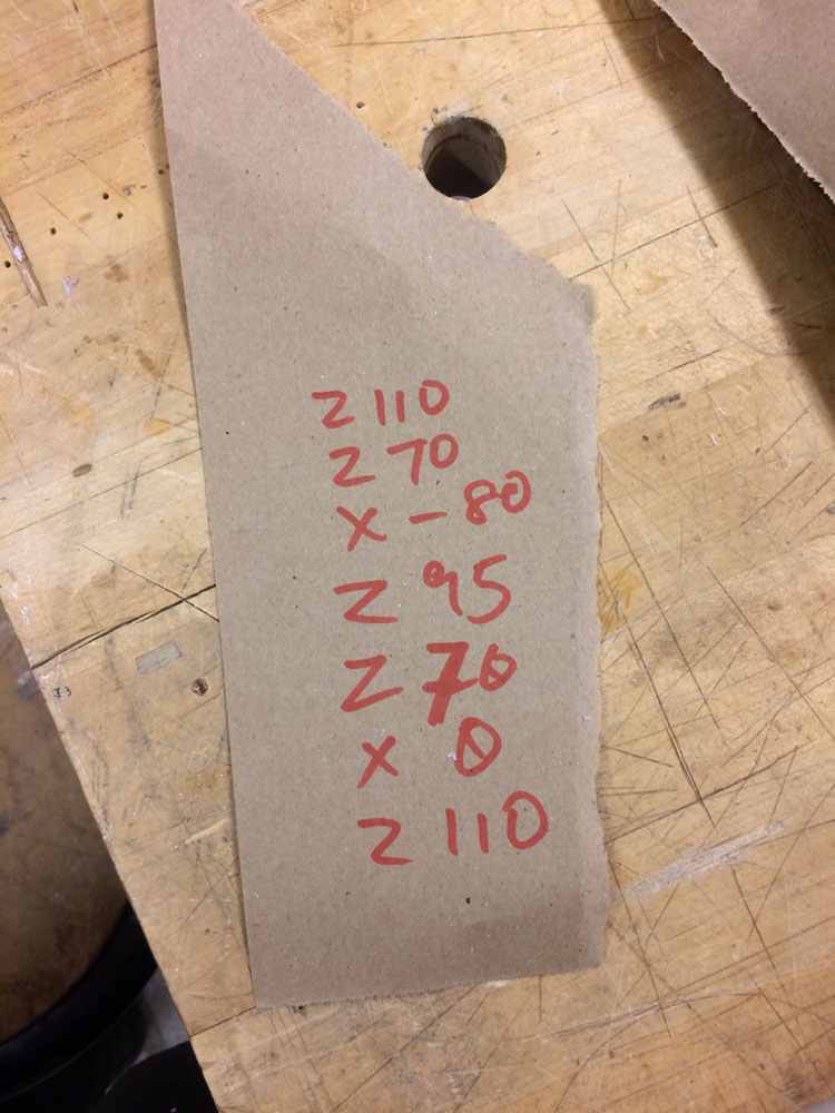
Coming back and forth from the ink pot. This would probably require returning the G-code to an absolute position of the ink pot every X number of steps.
Once we had VanGo assembled and knew the position of the ink pot, we were able to work out a simple G-code sequence for the ink to be reloaded each time. On paper our programme looked like this:
 In the Processing file or otherwise perhaps using a Python script we should be able to write a simple for loop inserting this G-code sequence into the main G-code at regular intervals.
Other minor concerns:
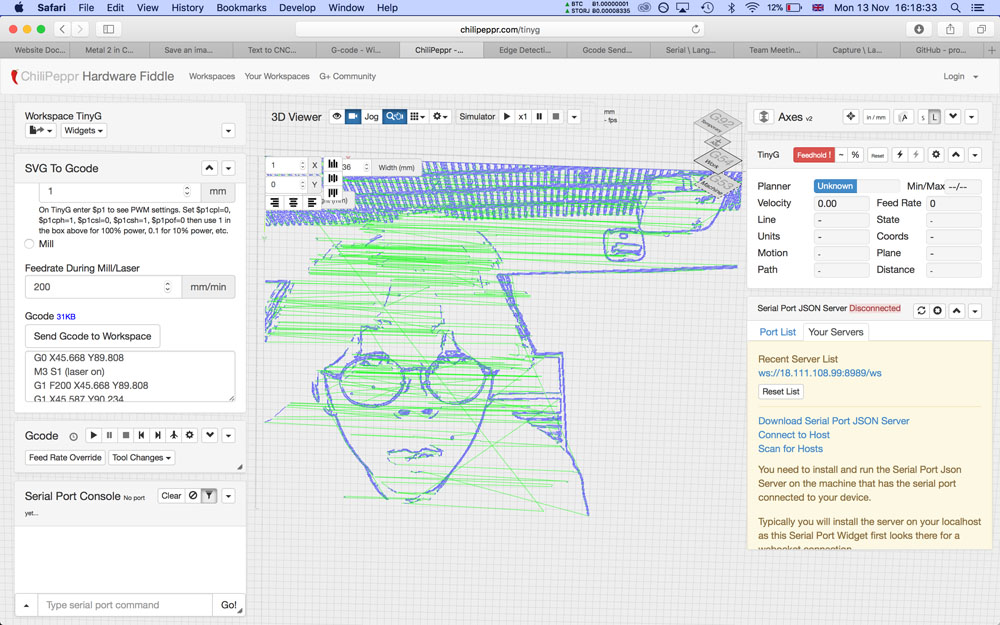
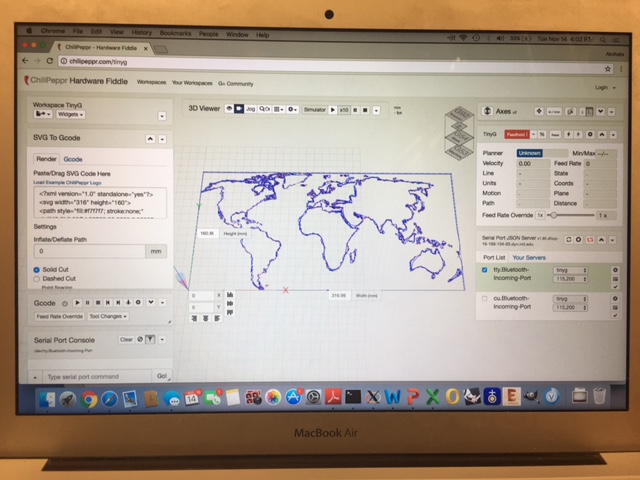
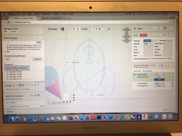
Cabling - both the power supply and the computer are now off the moving body of the machine so we need long enough cables to give it freedom of movement without dragging its entrails along. We had a few different options for entering G-code. One was Chilipeppr, which had a nice SVG to G-code interface, amongst others, for turning edges into movements. Another was the G-code module on Neil's mods, which is similar to the PCB cutting mod but has an extra module for outputting the job as a .NC file.
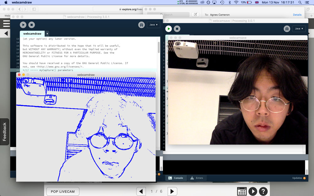
Both of these were quite feasible already. I was also wondering whether there was a more direct way of talking to the TinyG via a more flexible input, such as a live webcam image. So far I've been playing with Processing to generate the tool paths from a webcam, and with some serial setup should be able to send it directly to the TinyG.
Some side experiments in G-code
Following the note above, I attempted to use Processing to generate G-code from a webcam feed. The image to toolpath workflow turned out OK, but the difficulty was in actually getting the G-code onto the TinyG.
 I had figured that it would be possible simply by writing to the TinyG's serial port, which was more or less what Coolterm and the ChiliPeppr webapp was doing. To test this, I began by piping my G-code output from Processing straight into my terminal tty port
 cat /dev/ttys000, and it came out looking something like this:
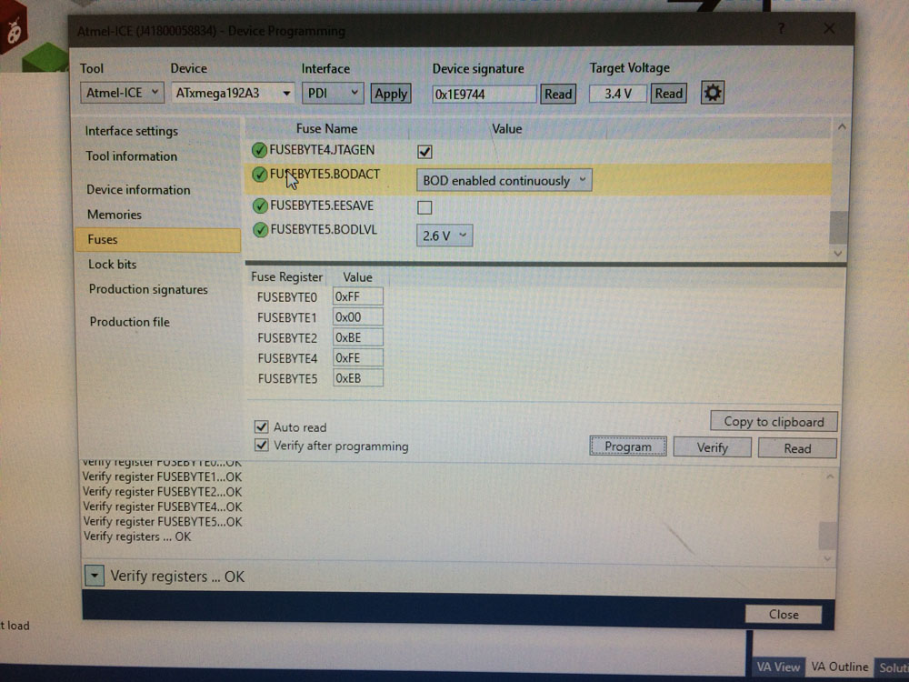
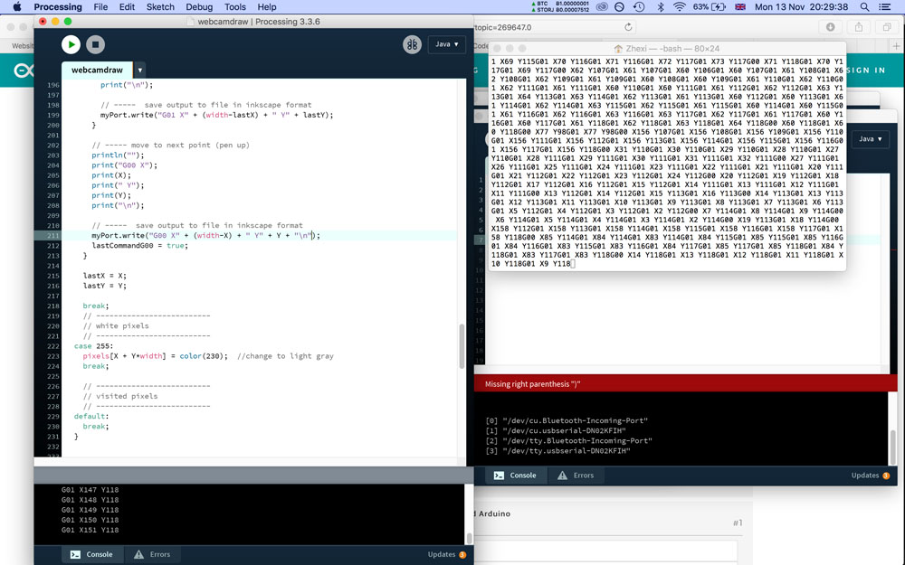 I should have noticed something to be amiss when this process was causing my terminal window to bug out, with strange errors affecting the way the characters appeared on screen. Nonetheless, it seemed to be putting out the right G-code in the right order so I decided to send it straight into the TinyG. This didn't seem to do much at first but very soon the TinyG's SpDir pin began to flash red incessantly, and the board wouldn't respond to the reset button or any other kind of interaction. This was worrying -- I thought I might've bricked it. Turns out the TinyG is actually extremely susceptible to these problems and there are several forum threads devoted to people who have accidentally crippled their board. The most likely reason seemed to be that by sending the G-code without the appropriate parsing or perhaps throttling the TinyG's limited buffer by sending it all at once caused an error in the firmware binary, basically screwing the whole board up inside out. To fix this, I had to follow TinyG's instructions for totally erasing the board using AVRISP2 and Atmel Studio 7 (now installed on the Arch shop atmelice computer) and reflashing the bootloader hex to it.
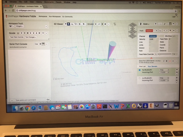
Chilipeppr - Testing and Validation
The first step is to download Chilipeppr. There are a few more steps before we're ready to use this to send G-Code to TinyG. We have to download the Serial Port JSON Server from here and build it. For Mac, the instructions to build are in the README.md file on the Github page. But we have to install Go and Go tools from this page before we can build.
SPJS currently maxes at 25,000 lines. The documentation suggests sending around 25 lines at a time each 1 second (1000 ms) depending on the complexity of the Gcode.
We can now see the serial port to the right bottom corner. We have loaded the sample G-Code from Chilipeppr. The simulation screen shows us the toolpath.
VanGo's dreams!