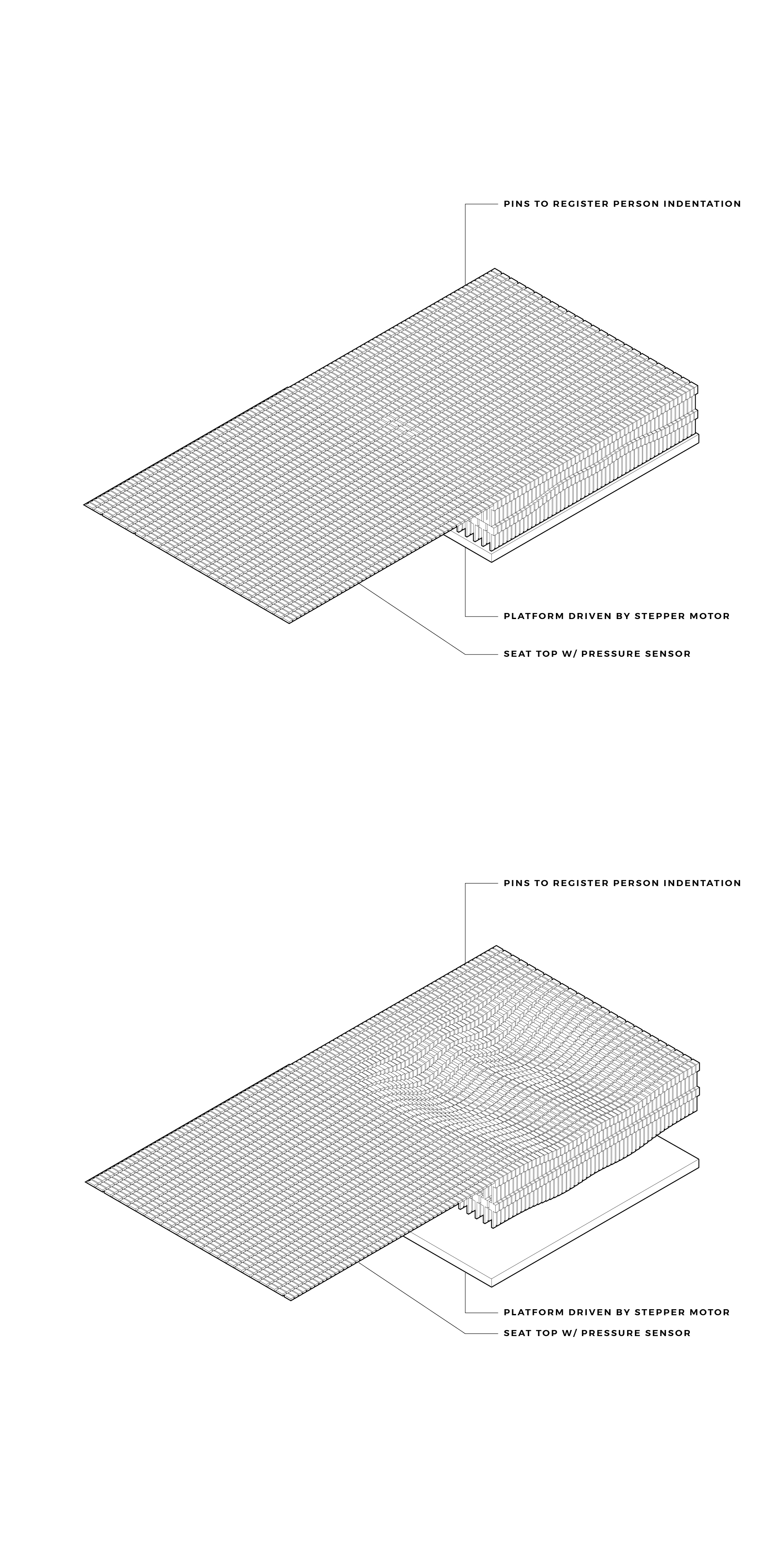
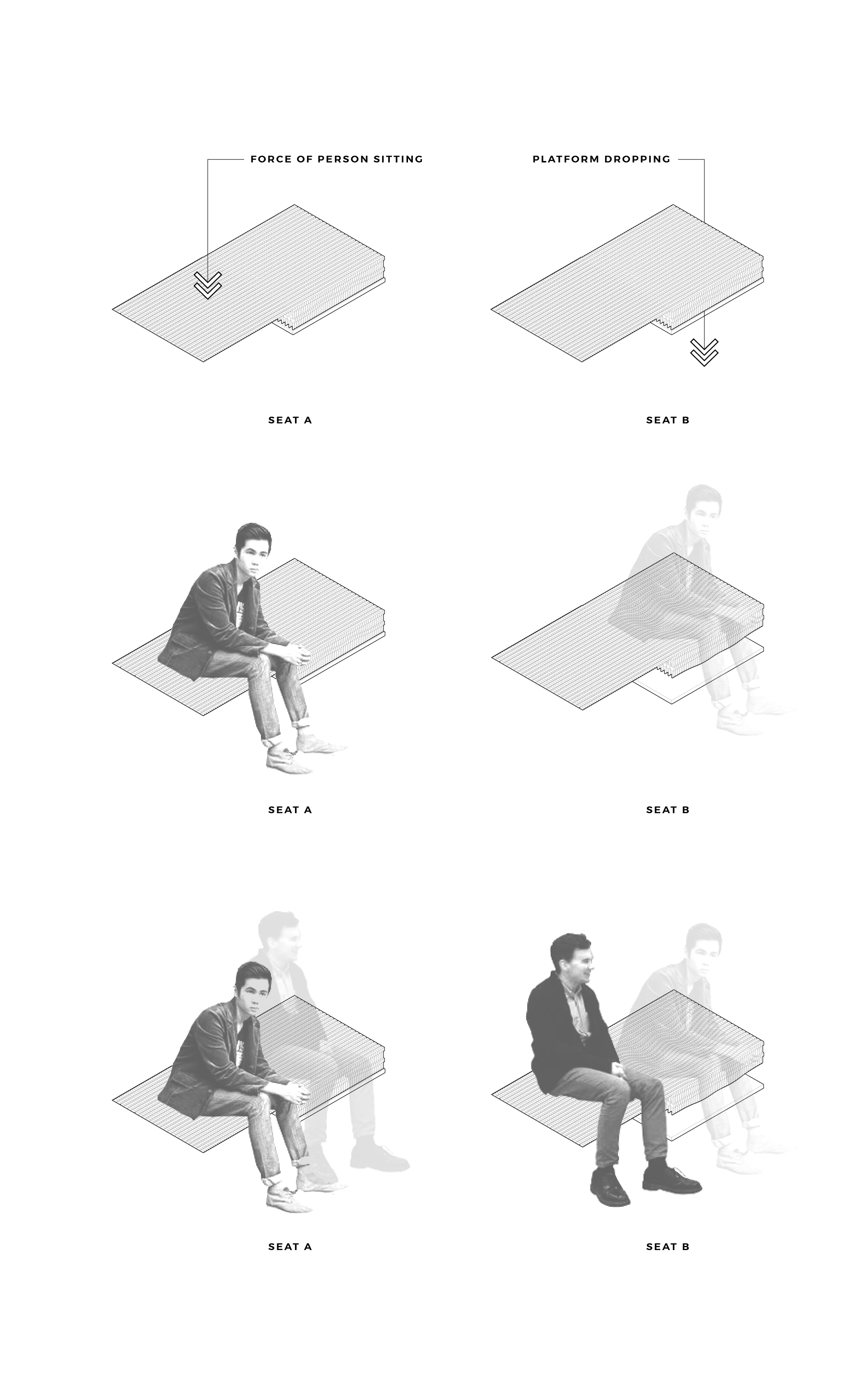
For my final project, I create a chair that physicalizes the remote presence of a person sitting. I achieved this through a pair of chairs that synchronizes the effect of a person using the chair! When a individual sits down on the seat, their presence is sensed through a capacitive touch sensor which triggers a stepper motor to move a series of pins down, forming the impression of that person in the remote seat. As the person stands up again, the pressure is removed which triggers the motor to move the platform back to the default position.
INITIAL CONCEPT
PROCESS
↓

Today, the platform for communicating with strangers in public space is through virtual means via the internet. I am designing a device that brings this form of connection back to the physical world. A person's presence will be physically manifested through a series of pins that form the impression of them sitting in a distant location. If another person is sitting on the adjacent seat at that distant location, they will see the presence of a person and have the opportunity to communicate through comfortable, virtual means.
Here is a breakdown of the integration of skills: computer-aided design - OVERALL DESIGN AND PARTS FOR FABRICATION computer-controlled cutting - SEAT PINS electronics production - INTEGRATED WITH INPUT/OUTPUT 3D scanning and printing - COMMUNICATION CONTROLS OR SCAN OF MYSELF SITTING ON SEAT electronics design - INTEGRATED WITH INPUT/OUTPUT computer-controlled machining - FABRICATION OF SEATS? embedded programming - INTEGRATED WITH INPUT/OUTPUT AND COMMUNICATION DEVICE molding and casting - FABRICATION OF SEATS? output devices - STEPPER MOTORS machine design - WILL BE USING SOMETHING SIMILAR TO Z-AXIS FOR MOVING PLATFORM input devices - STEP RESPONSE PRESSURE SENSOR interface and application programming - COMMUNICATION DEVICE networking and communications - COMMUNICATION DEVICE AND COMMUNICATION BETWEEN SENSORS AND ACTUATORS


I tested out a Nema 17, 12V stepper motor with my stepper motor board. Initially, I uploaded a simple move motor code from the Arduino IDE. The motor wiggled back and forth but did not rotate properly. Jonah assited me with troubleshooting the issue. There were a series of tests that I did to see where the problem was. I first plugged in wires into two of the motors pins to find the pairs. In order to determine a motor pair, you must short the wiring and rotate the motor. If you feel resistance while turning, congrats! You have found a pair. I verified my wire pairings were correct. Then I moved on to test out the code to see if this was the issue. I uploaded the hello.stepper c-code and the motor still wiggled. Then I tried out different batteries, still no luck. Finally, Jonah suggested I use the Easy Driver break out board, when I did this, the motor turned perfectly! I found the issue was with the motor drivers so I verified that my connects were correct, after doing this, I was still unsure of the issue with the movement. Later in the week, I discovered that others were experiencing the same issue because the routing of traces in the example board were slightly incorrect. At this point, I was unable to recreate the boards but for future reference, this was very useful to know where the problem lay.

To triple check the issue, I tested out my boards with three different motors - one with a lead screw, one that required 5V and another that required 12V. They all failed to work with the motor drivers on my board but successfully worked with the break out board.
I began testing my loading sensor with the Arduino serial monitor. The end goal was to use the input data to control movement of the stepper motor. This step ended up being fairly challenging as I had to parce out some of the python hello.loading code into Arduino and read the values of the sensor. The stream of serial data that came in was in an illegible format intially (to be expected of course!) I then copied part of the python code in the hello.loading.py file in order to parce the data. It took many attempts at troubleshooting before I was able to successfully read the input values.

I then discovered that the data was being parce by the detection of a header attached to a string of input values. The code finds the header then is able to decode the input values as it does in the python script. Once I figured out how to implement this logic in the C code, success! The data steam was coming through with legible values.
The next step was to then create a binary threshold so the input values were converted into 1's and 0's based on the value of the serial being read. I separated the data into values above 550 and below 550 to determine whether loading is detected or not. After testing out the sensor with the motor, this value was adjusted.
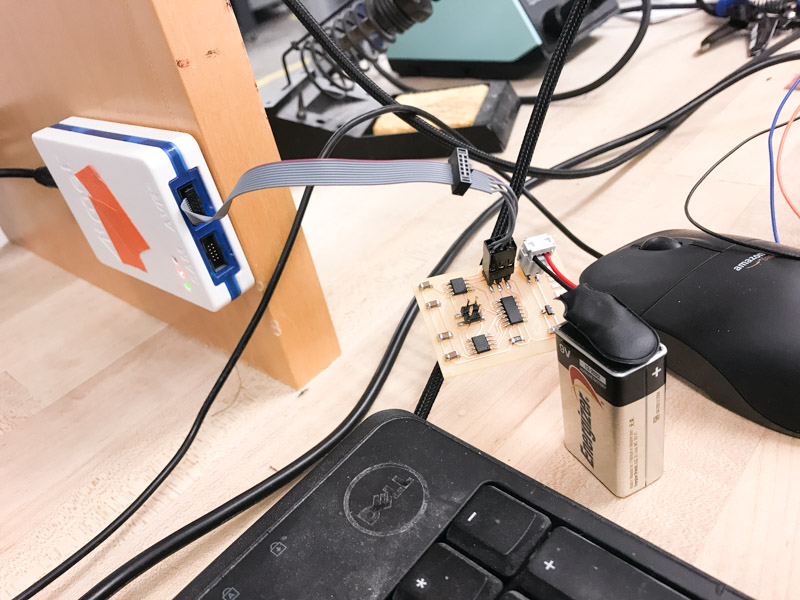
Then, I began my wired networking connecting the tx pin on the loading sensor board to the rx pin on the stepper motor board. The goal was to have the motor board turn a fixed number of steps when pressure is initially sensed and then turn backwards a fixed number of steps when the pressure is released. Once this was done, I successfully networked my sensor and motor boards! When touch was sensed, the motor moved a given number of steps in one direction, and when touch was removed, the motor moved in the same number of steps in the other direction.


After arriving at a comfortable place with my electronics, I started to work on the final modeling and fabrication of my chairs! I modeled my project in Rhino and created the pins and stoppers by writing a grasshopper script. My project was very much fabrication heavy. I designed the stepper motor to platform connection, the platform and rack guides, the pins and and sockets, the envelope and the legs of the chairs all in Rhino. The project consisted of two chairs, one which held the capacitive touch sensor and the other with held the pins controlled by a stepper motor with a lead screw and platform. I initially designed the platform to be moved by two stepper motors on a rack and pinion system similar to the machine design week. Justin and Calvin both advised that I use a stepper motor with a lead screw and attachment for higher fidelity control.


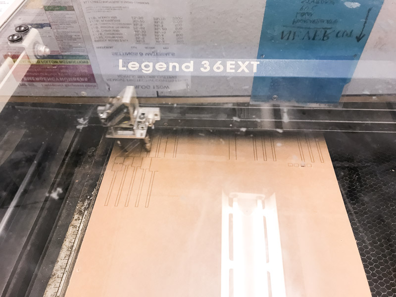
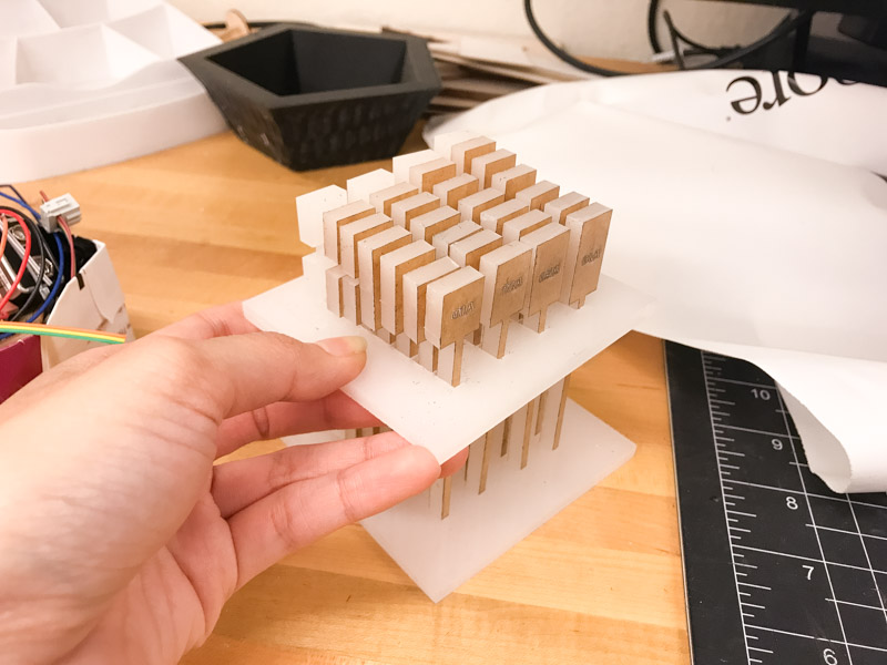
I then moved onto setting up my fabrication files. I used the lasercutter for most of the pin and chair parts and the 3D printer for the lead screw to platform attachment. The cutting process took much longer than expected. I used 1/4" MDF which required a very slow speed with high power to cut all the way through. I tested a round with multiple cuts but the top of the material burned too much and created tapered pieces instead of straight cuts. Each sheet took 3 hours to cut.

Testing of joints and pin sockets!


ELECTRONICS
WEEKLY PROGRESS
↓
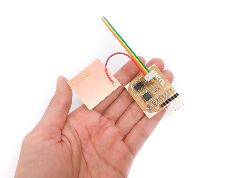
During the input devices week, I created a step response pressure sensor which will be used to determine if a person is sitting on the seat or not. I also would like to use the range of pressure to determine how far the platform goes down. For example, if there was a lighter person, they would make half the impression of a heavier person.
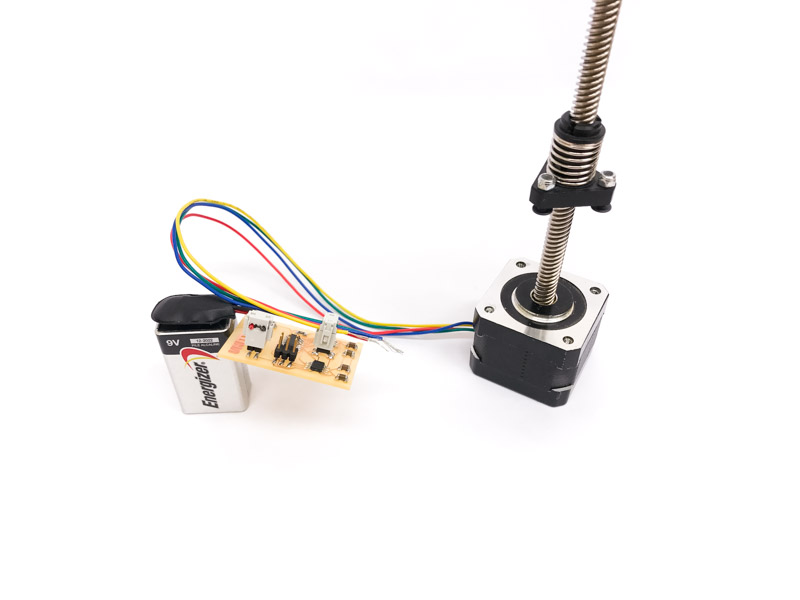
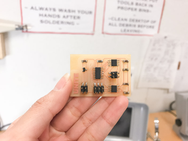
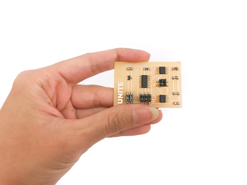
For my output device, I created a stepper motor board which will then take the pressure input and move a given amount of rotations in order to drive the platform to particular heights. I still have to work on the c code and networking to integrate the sensor and actuator.
Above are process photos because I used a different output device in week 08!
FABRICATION
WEEKLY PROGRESS
↓

I created a 1:1 mockup of a section of the pins, surface and moving platform. The holes which the pins sit in are not snug enough, partially because the Acrylic material was not exactly 1/4" thick. I need to do studies on the best sizing for these openings.
I've been thinking about the materiality of the final seats and am currently considering white acrylic. This may be too heavy for the stepper motors that I purchased, so I am also thinking of using MDF or basswood.
PREVIOUS IDEA
PROCESS
↓
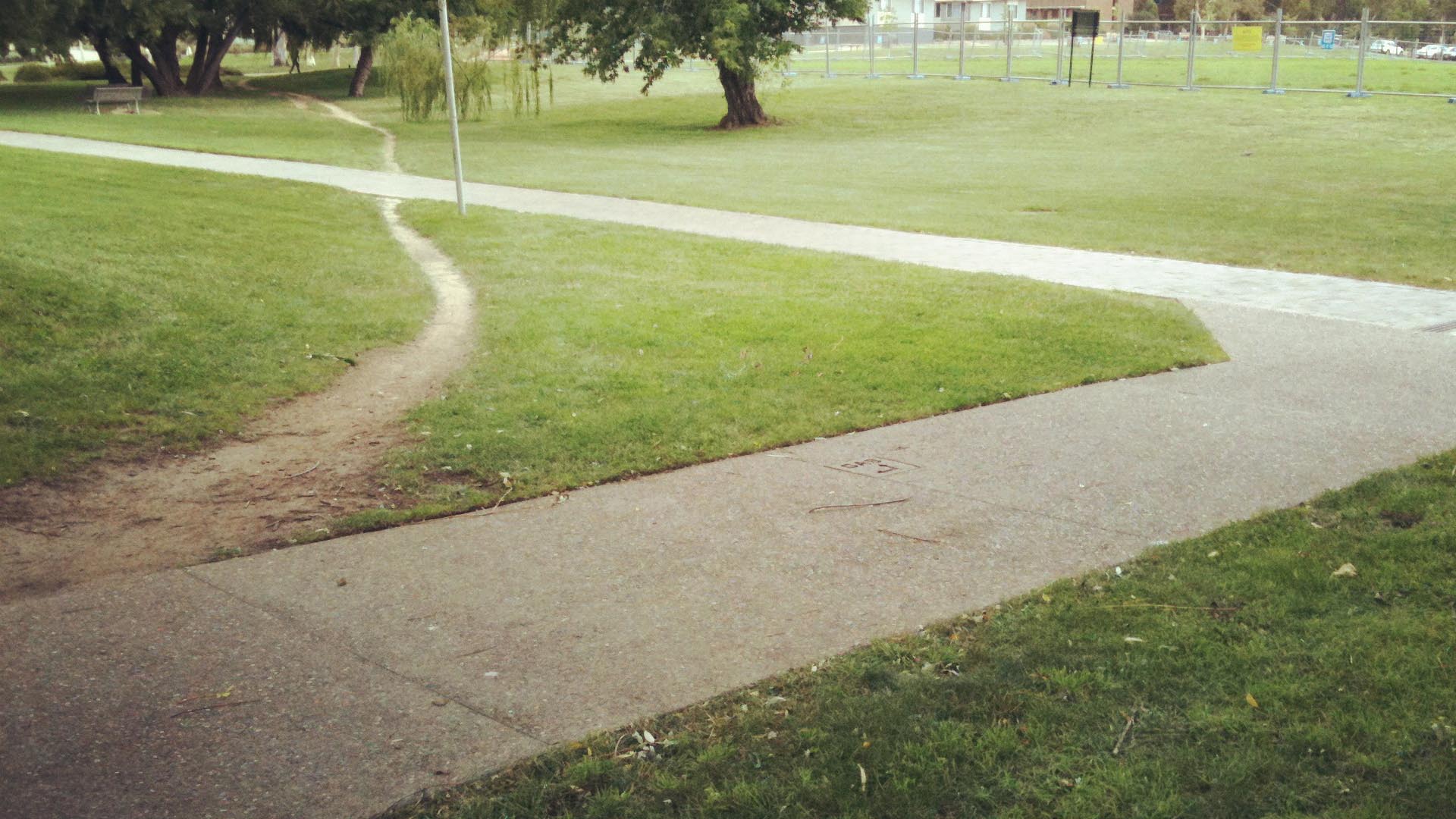

Inscribing the path most traveled into architectural space through the implementation of light intensity determined by image sampling of usage over time.
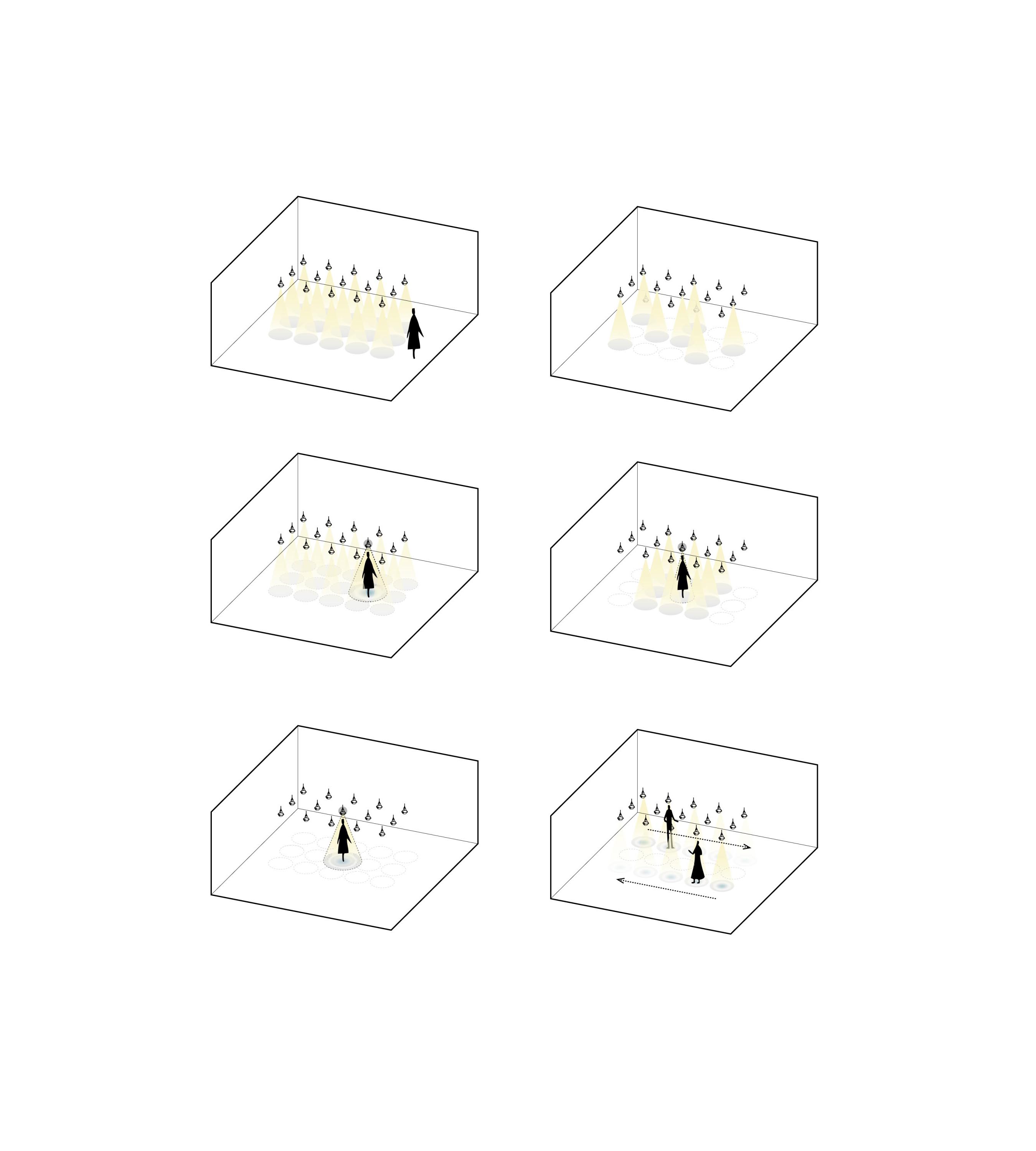
I'm planning to use thermal image samples to record movements through space. These samples will be collected every ten seconds to generate a log of concentrated areas of occupation. The intensity of the light in regions which recieve the most activity will be at full strength whereas areas that are not used as often will be dim. The goal is to manipulate space through time based on paths of common travel.
If dimness is too challenging, other means of transcribing the data into space are: light hue, fans, or projected visualizations.

PREVIOUS IDEA
PROCESS
↓
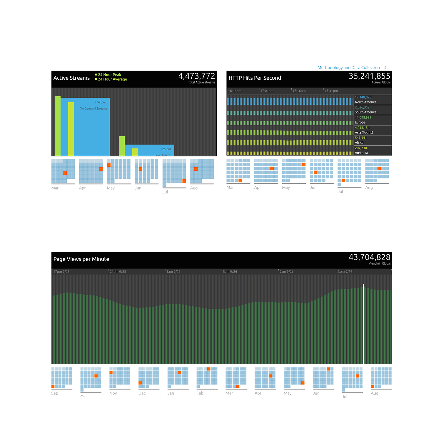
On Akamai's website, they include real time internet statistics with their global data. Although this only reflects a percentage of traffic, for my purposes, the abstraction of this data will give an accurate representation of internet usage.
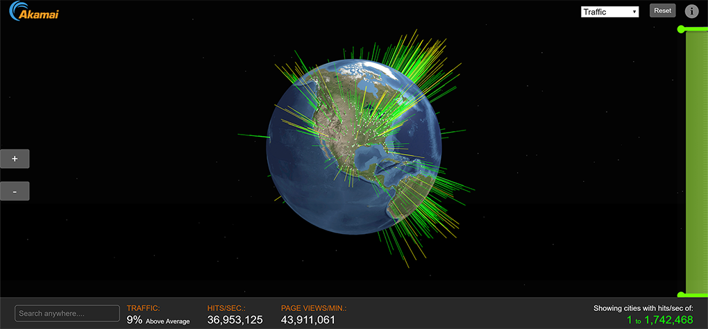
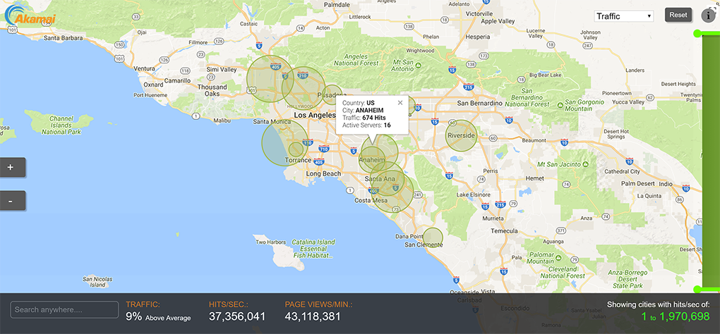
The idea is to scrape their webpage with a Python script. Is this legal? I'm not sure, but since they are an MIT founded company, perhaps I'll try to get in touch with them. One of their many interfaces allows the user to input a specific city and the webpage will give you general traffic information. I plan to translate this into physical form.
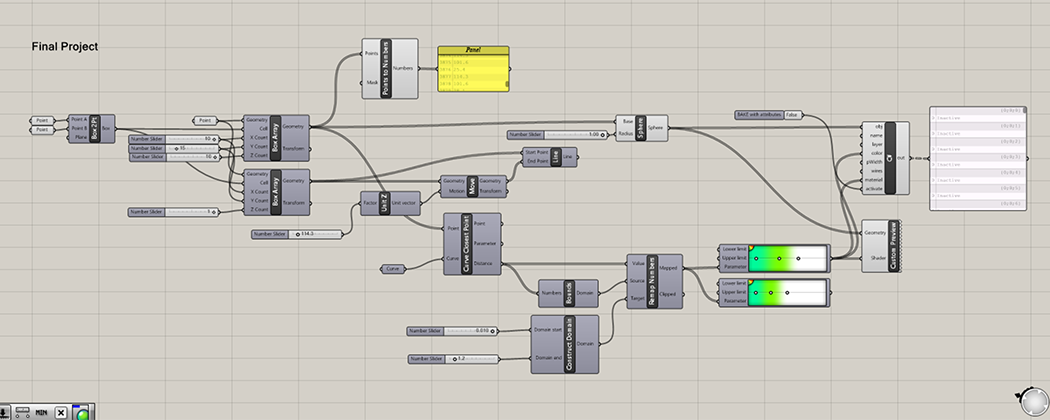
This is the grasshopper script I used to generate my working 3D model.
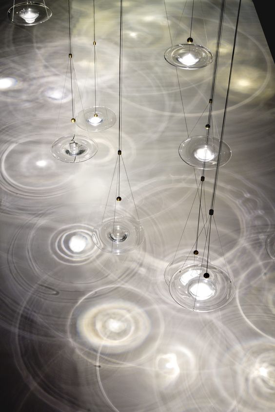
Each vertical string of light will represent the internet usage of a single city. I will organize the cities by region so there is a gradient in lighting (ex. when it is night time is North America, it will be day time is Asia, thus reflecting in the illumination). The series of lights on each string will represent the intensity of real time traffic.