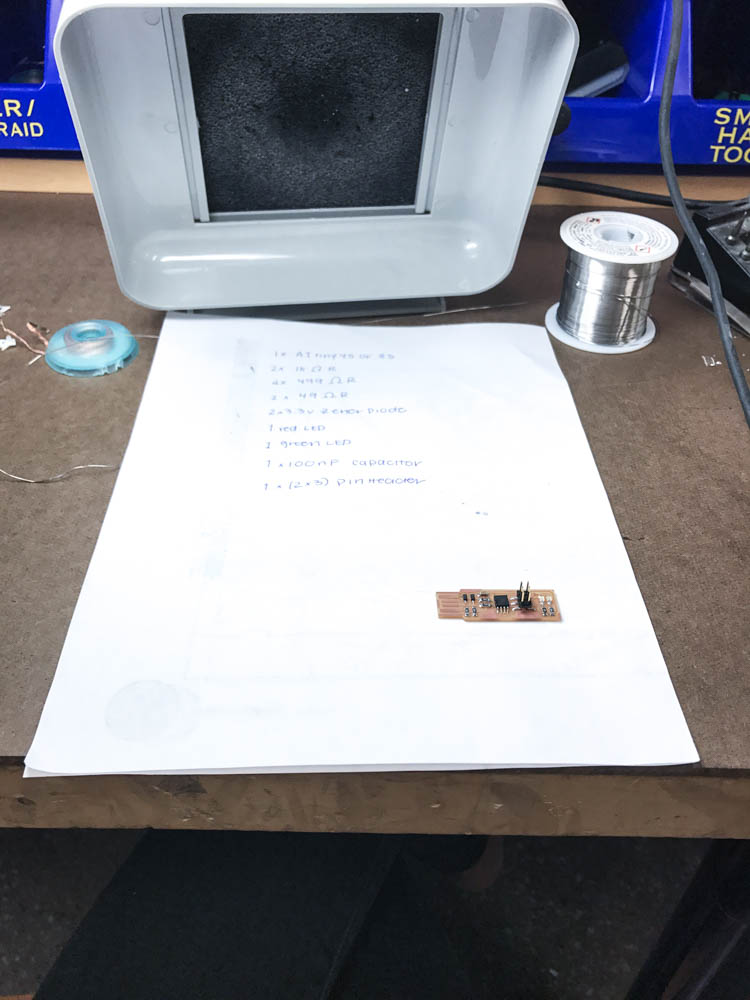
PROCESS
THIS IS HOW I GOT THERE
↓
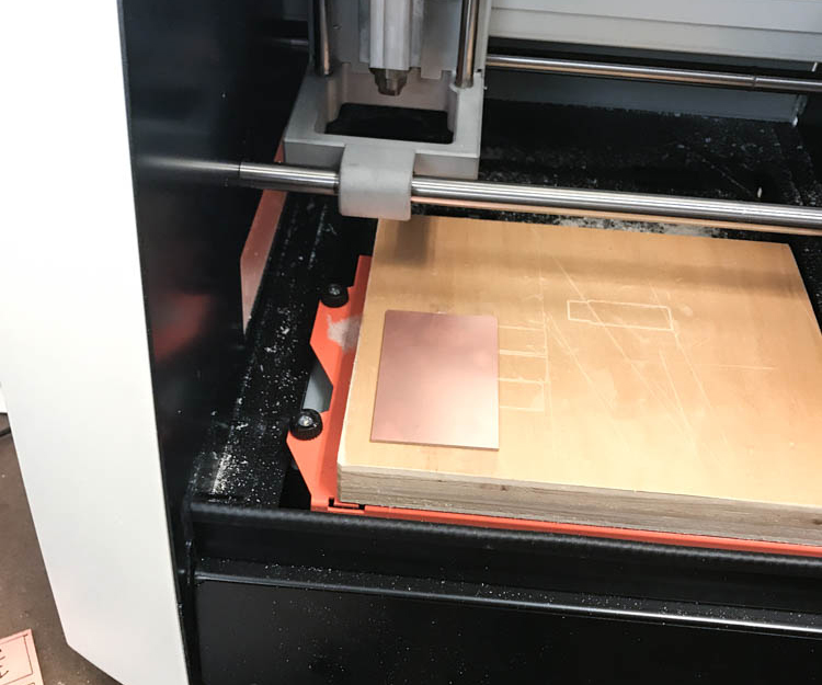
With the help of Jonah, I setup the mill. First I aligned the origin point, then loaded the png into mods and finally started cutting. There was a hiccup along the way, after the mill cut the traces, I began cutting the outline file. Instead of cutting at the same z-height, the bit began six inches above the set height. Justin and Jen helped me fix the issue! Leason learned: do not set the z origin to '0' on the SRM-20.
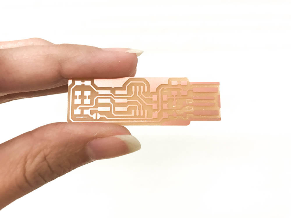
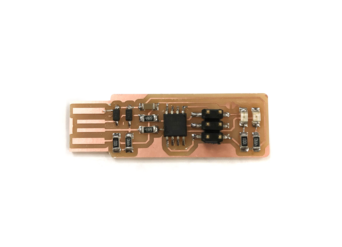
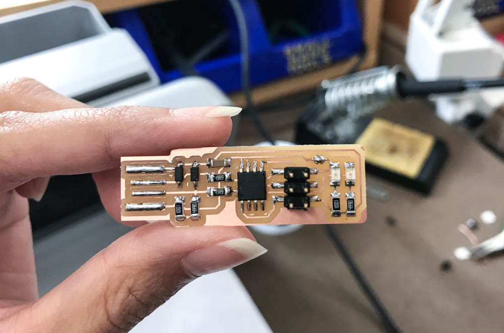
TA-DA! My milled board.
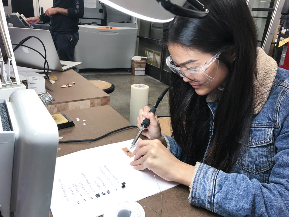
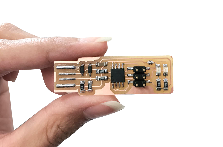
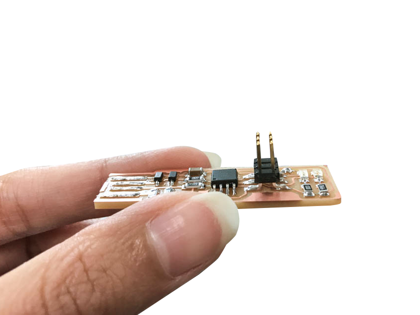
After several attempts at soldering, which was much more tedious than it looked, I found success. I learned that my small hands and long nails were perfect for this task.
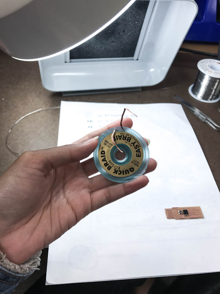
Shout out to my new best friend, rosin braid, for being so helpful throughout the process. Don't know how many spare boards I would have had to mill without you.
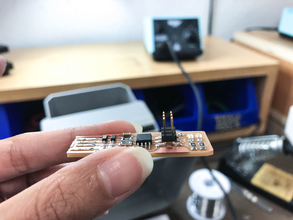
The whole process took about five hours to complete. This week, I learned how to produce many different types of 'bad' connections. After a number of attempts, I now know how to produce 'good' ones as well.
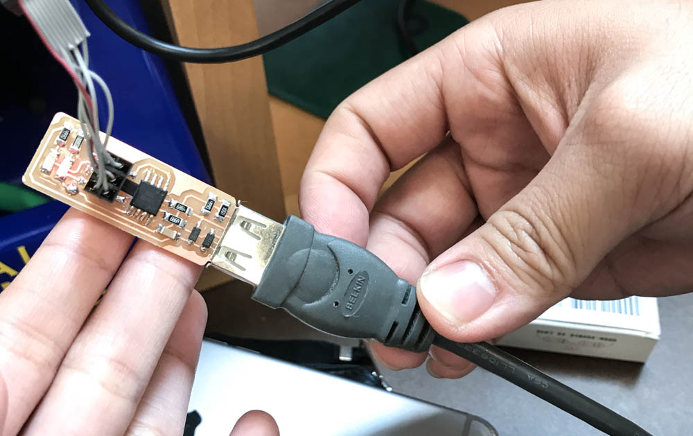
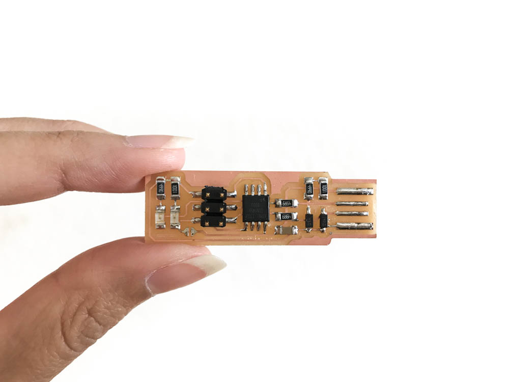
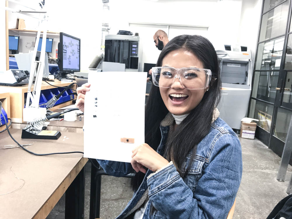
My finished programmed PCB!