PROCESS
THIS IS HOW I GOT THERE
↓

I first created my schematic file in Eagle. The program was fairly easy to use, though the functionality is a bit more outdated than other Autodesk programs.
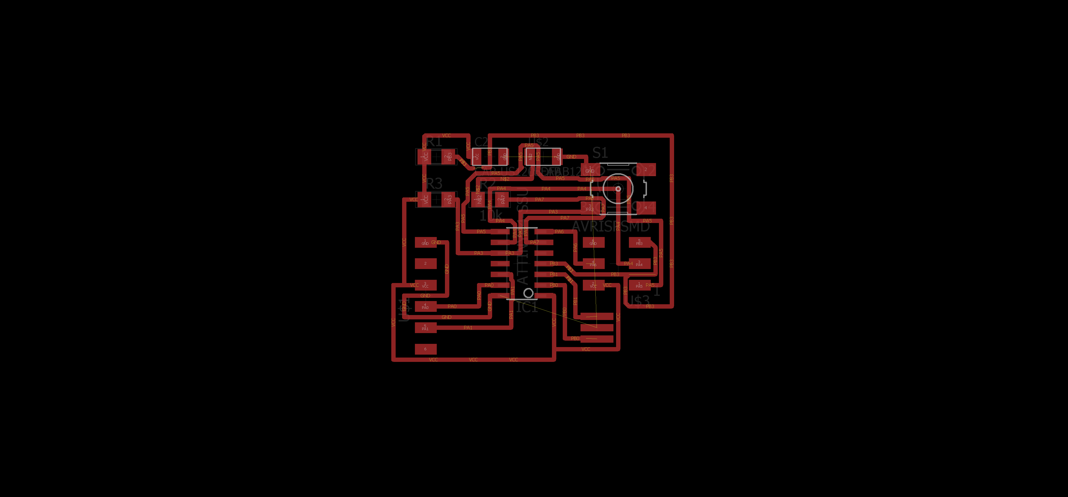
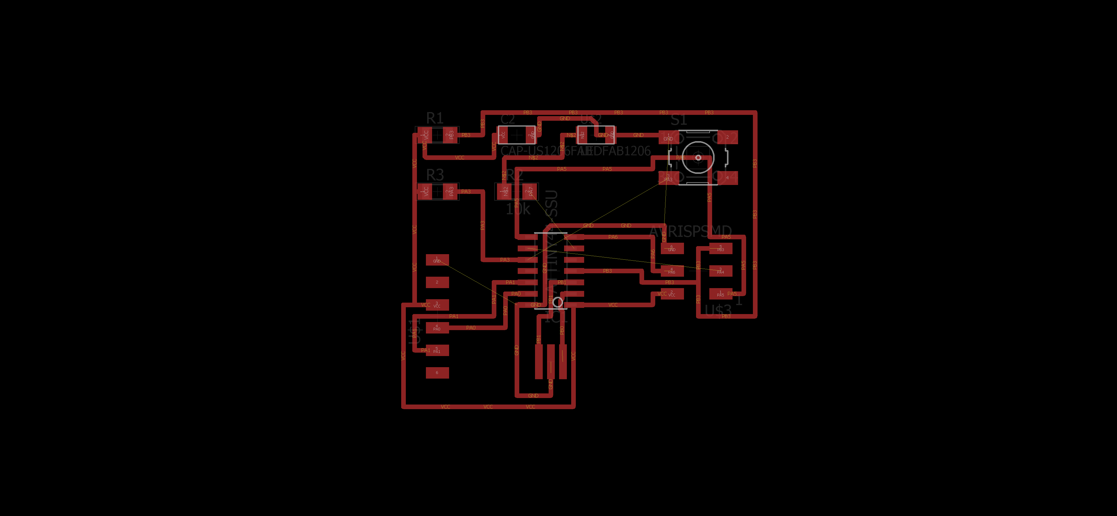
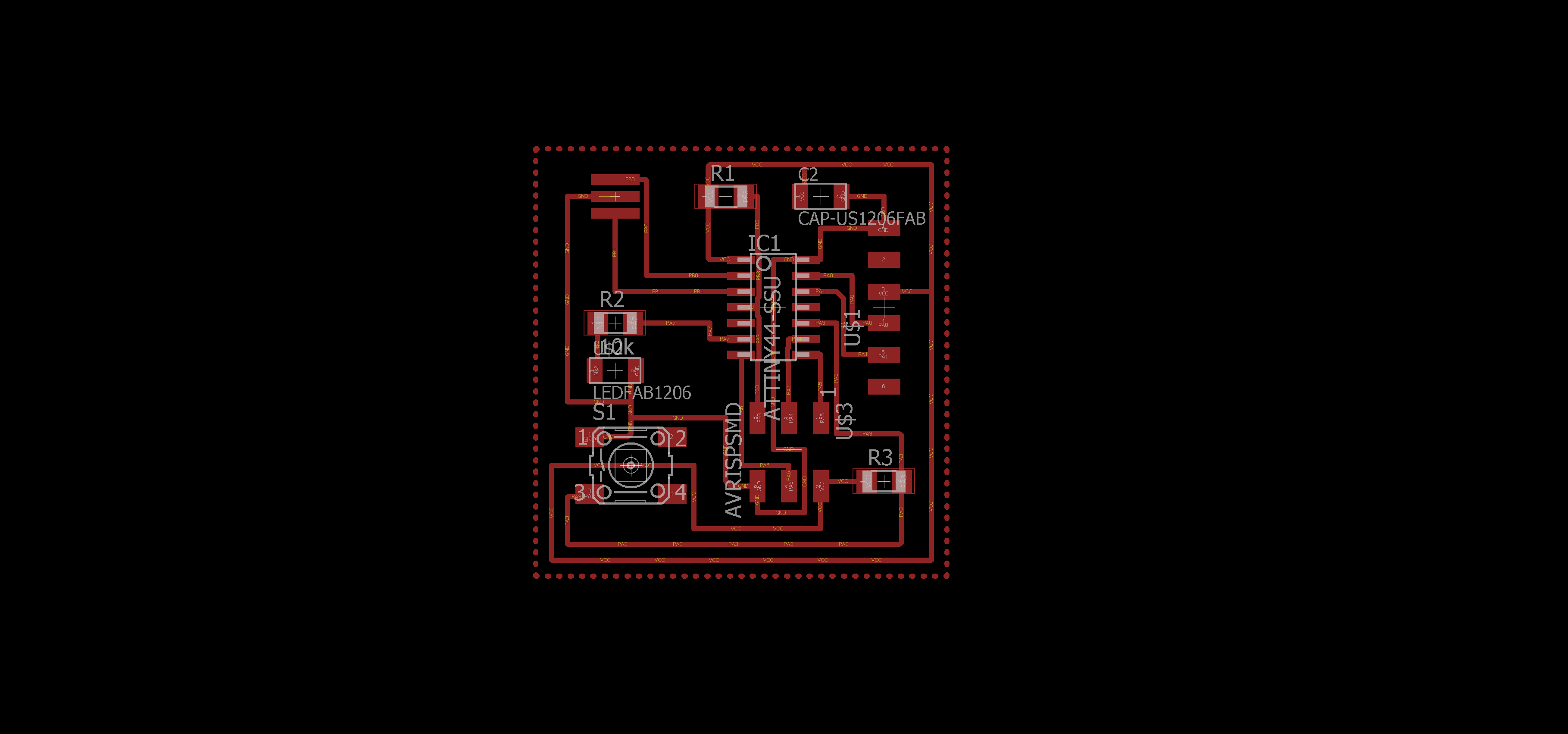
After creating the schematic, I then proceeded to generate a board file based off of it. It took several tries for autoroute to work. I then attempted to manually route the connects which Jonah suggested would be good practice. Also, my connections were much cleaner when I routed the board myself. However, I later found out that two of my connections were too close to the ATTiny pads.
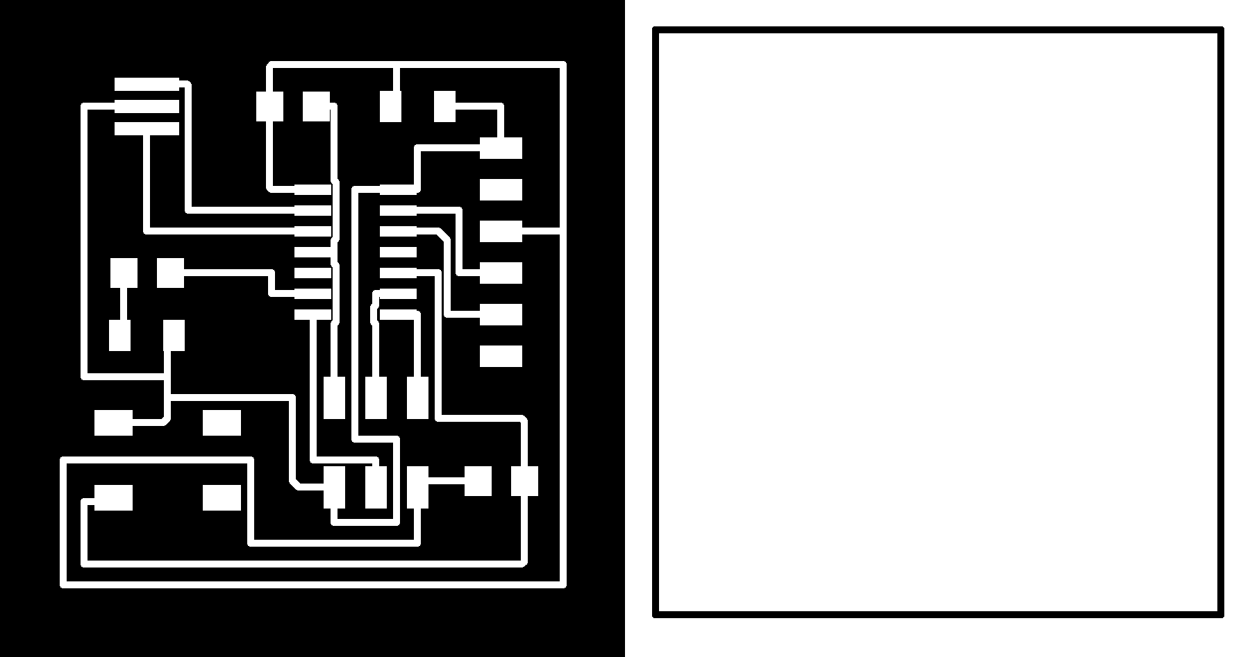

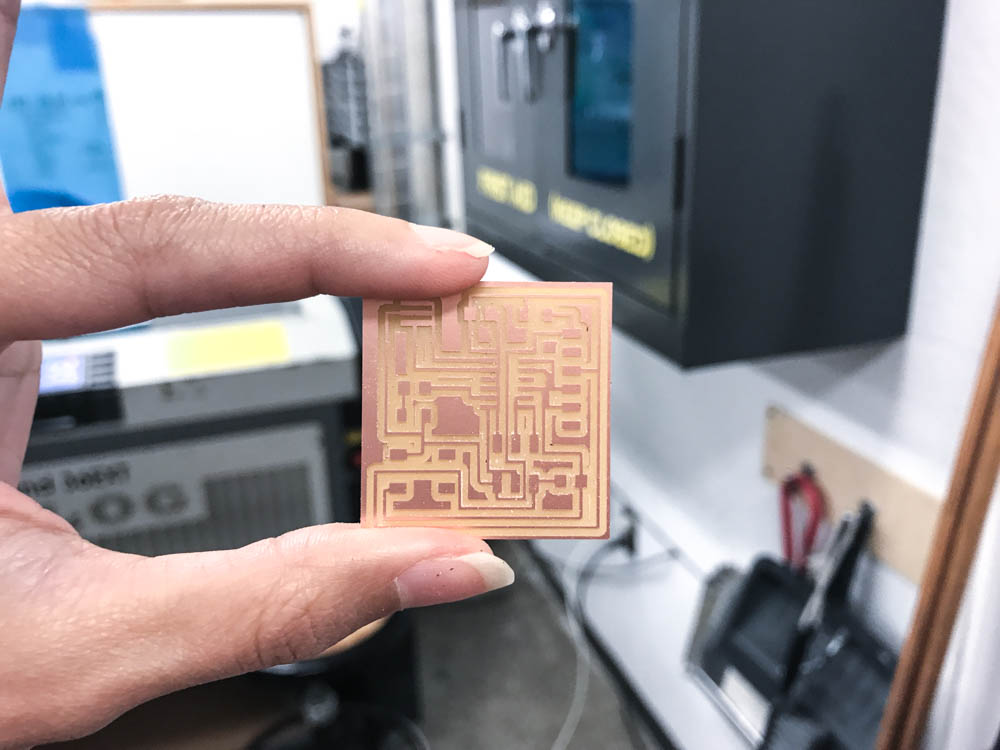
Once I finished the board file, I generated monochrome PNGs then imported them into mods to mill my board with the SRM-20.
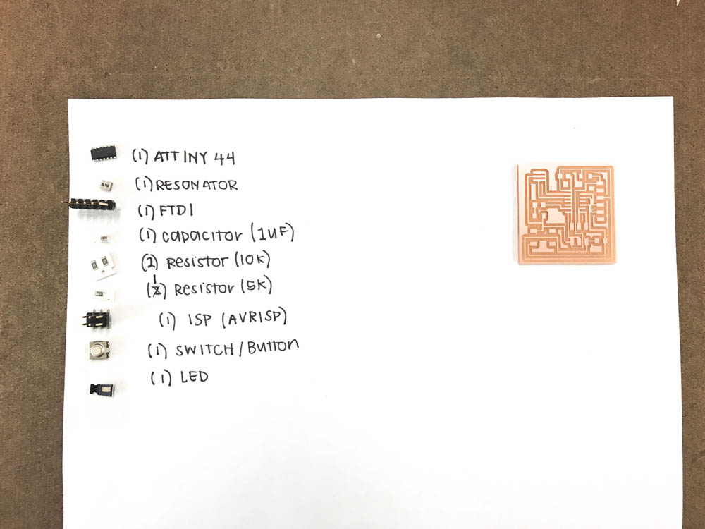
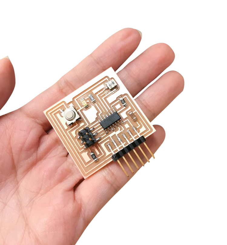
Gathering all my parts!
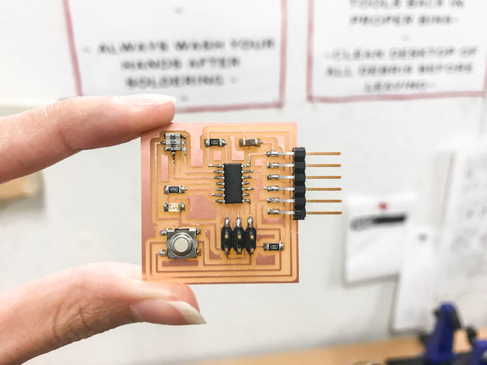
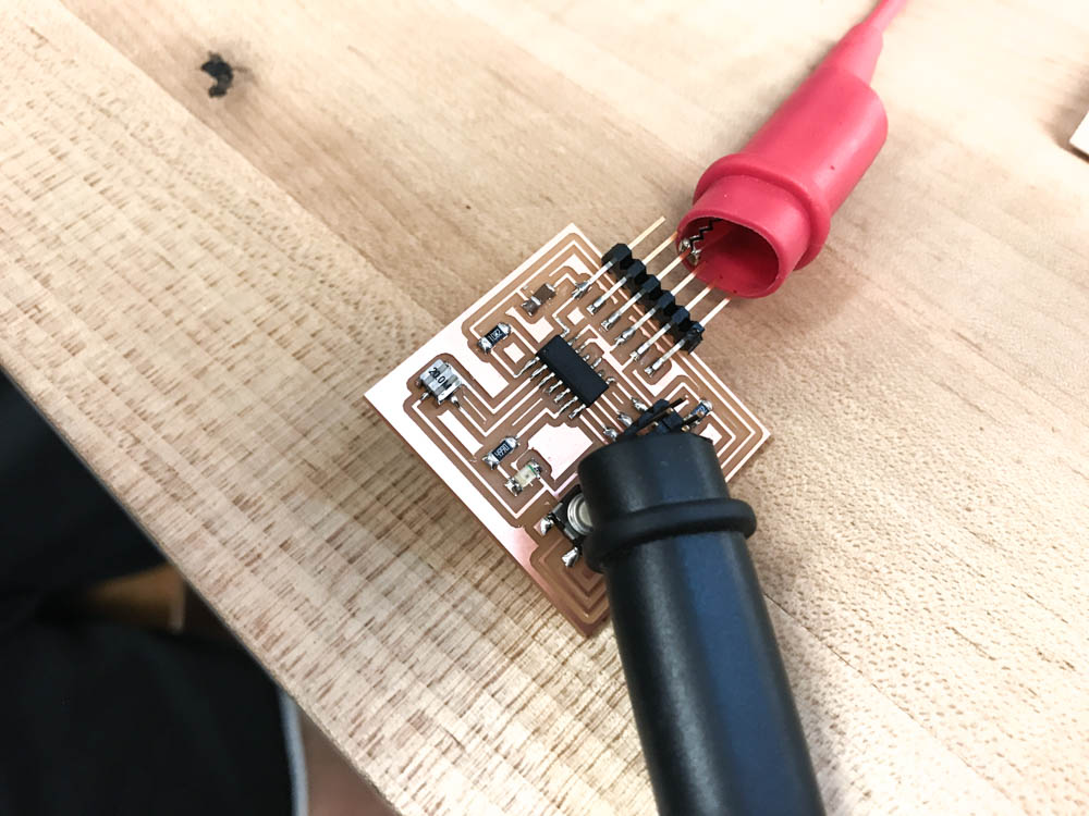
My final PCB. I made a mistake with the crystal and accidentally welding two of the pads to adjacent traces. Whoops. I removed the solder with the rosin braid though it's difficult to see in the image.
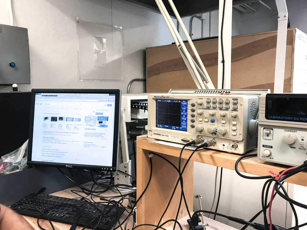
Jonah taught us how to use the oscilloscope! We attempted to simulate my board, but I later found out that it was not working because I had two bad connections.
Powering the PCB with the power supply!

With much help from Jonah, I then attempted to program my PCB which, as I mentioned, did not end up working. This was pretty sad because my soldering was much improved and I spent a fair amount of time working on the board. After about three hours of troubleshooting, we discovered that two of my traces in Eagle were too close together. I then found out about grid sizes which would have enabled more freedom while I was routing the board. All in all, I learned a lot from this week!