PROCESS
THIS IS HOW I GOT THERE
↓
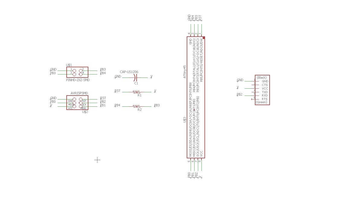
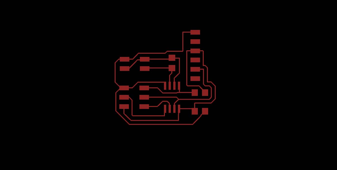
I first started by designing and my step response pressure sensor in Eagle based off of the hello loading board on the class website. I manually routed the traces in Eagle.


Above are the trace and outline files which I milled on the SRM-20.
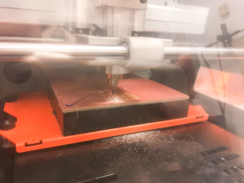
This was the first time I had issues with milling on the SRM-20. It was an easy fix, but the sacrificial layer on the mill was lifted up in the center which caused the mill to turn jagged towards the center. Surprisingly, this did not break the 1/64" end mill. I ended up having to discard the sacrificial layer of copper on top of the bed because it no longer stuck down flat. After that, the job milled very nicely.
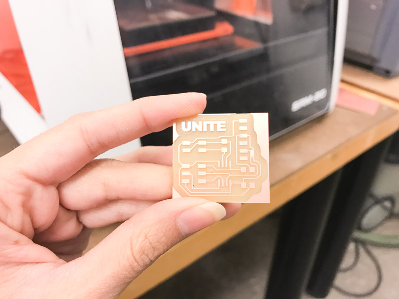
My milled board!
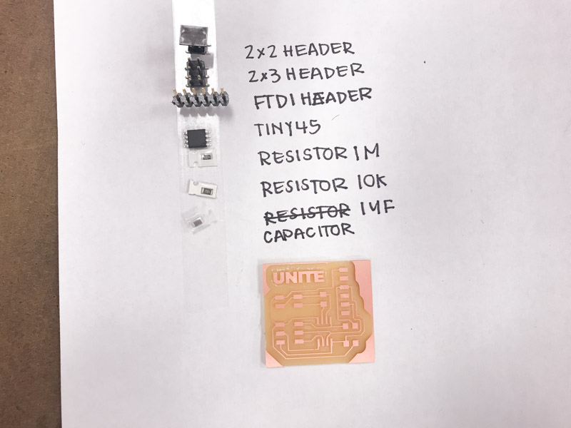
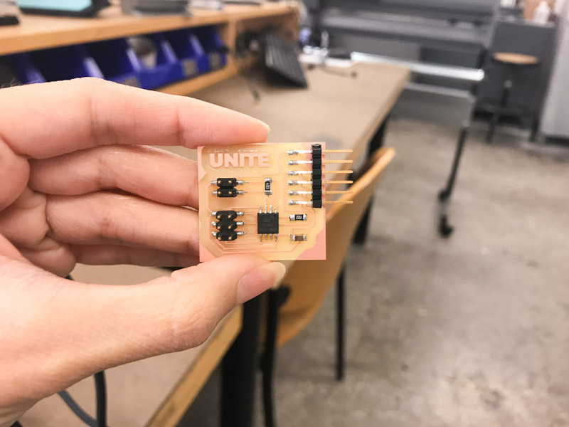
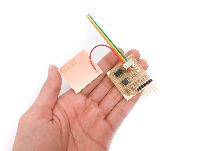
I then collected the components and soldered my board. I've become very confident in my soldering skills! Completing my board took around 10 minutes.
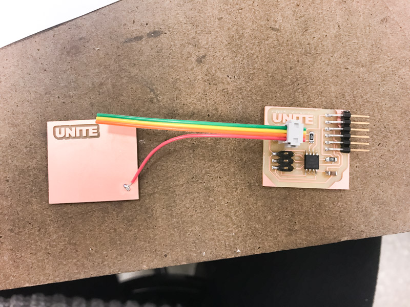
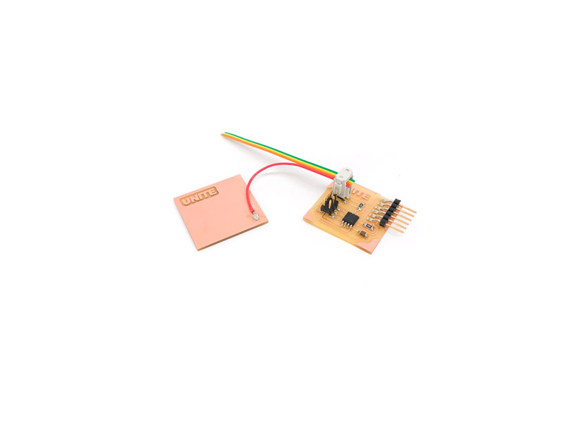
I then created my touch pad and soldered a connection to the 2x2 pin header. The wire connected the touch pad with the sense pin.
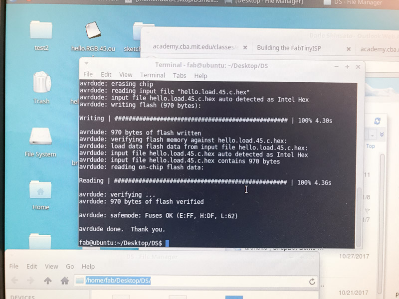
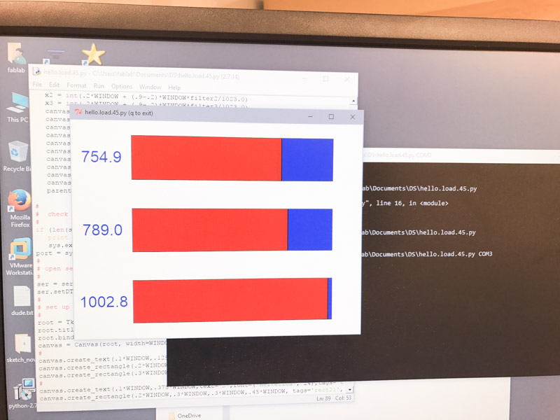
Creating the .hex file off of the hello loading c code and programming it onto the board was very quick and went smoothly. However, I had trouble launching the python visualization.
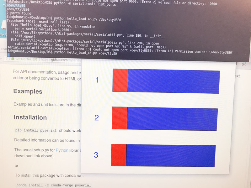
To launch python I typed "python hello.loading.45.py /dev/ttyS0" into the command line. To find the serial port, I typed in "python -m serial.tools list_ports". When I launched python, the script opened but did not display any input from the sensor. This was a sad moment, one which I am becoming quite familiar with. While troubleshooting, I revisited by Eagle board file to see if I had any wrong connections even though I successfully programmed the board. Though I know I shouldn't trust my intuition especially in electronics, I was fairly confident that the board was wired correctly. I had a hunch the issue was with the serial port because the board was programmed and the FTDI was plugged in correctly. I spent hours searching for more information on the serial ports and even tried plugging in the FTDI usb into every port. The next day, Jonah helped troubleshoot the issue with me! It turned out my hunch was correct, and the issue was with the serial port. We launched Arduino and opened the serial monitor to see if there was any input at all from the serial port. Turns out, there was nothing. We launched Arduino on windows and saw there was serial communication and could not resolve the issue on Ubuntu. The solution was then to launch python on Windows. I found the serial port was COM3 and we used the same command. This resulted in an error message saying we needed to install drivers for python. After doing this, the visualization launched and worked!