Final project
Metheny
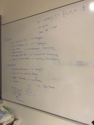
For the final project, Andrew and I decided to work on a device that requires skill from most of the week. In the beginning of the semester with decide on working on a music machine, and while going through the course we refine the ideas into a more concrete design. Over a number of meetings we discussed what component are needed for the device, how it should operate, how the interface looks like, and more importantly what is the timeline of the project.
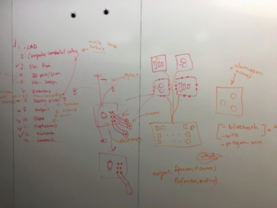
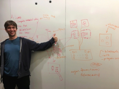
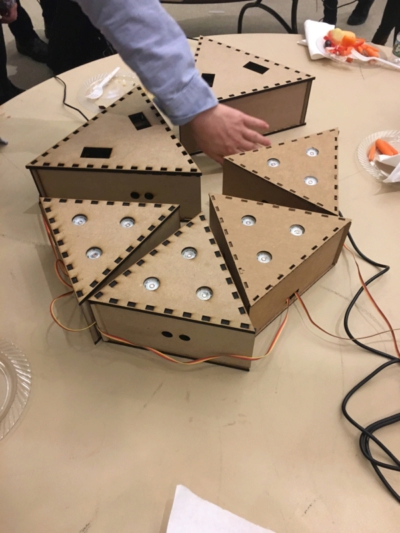
he metheny is consisted of multiple pieces that interact with each other through ultrasound. They also interact with the user network. The user define what each piece does over a 8 step tempo. Moreover the pieces measure their distance from other pieces and modulate the rate they are producing the tempo. each piece is enclosed and only the sensors, actuators, and network components are visible. We started by sketching the general outline, and noting how the material from each week can contribute the design. One of the things that become clear immediately, was that the first step should be figuring out the electronics, and communication, since they to large extent constrain the progress over project.
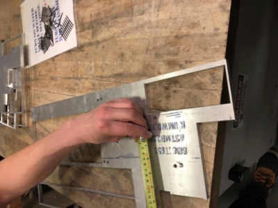
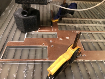
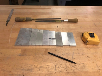
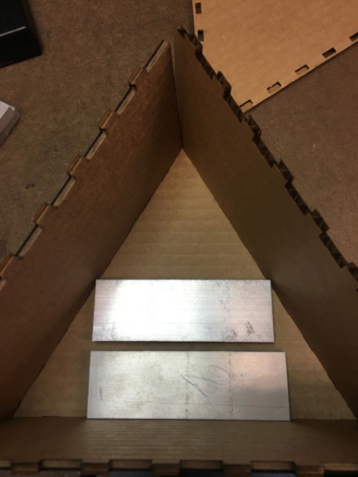
The devices create sound either digitally via a set of speakers, or mechanically. We decided that this would be a good division of the work, since it gives us a way to go through each design and manufacture step fairly independently while working on some parts jointly. I decided to focus on the mechanical piece. The first parts that we made was aluminum bars for the the mechanical piece. We used waterjet to cut the aluminum with the help of a person who was familiar with the machine and safety consideration. After machining with polished and cleaned them for testing their tuning.(
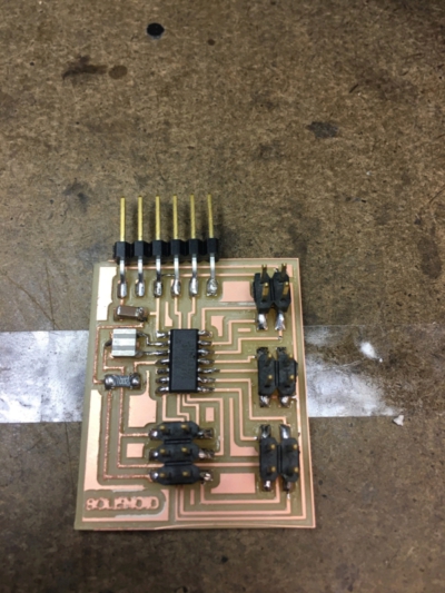
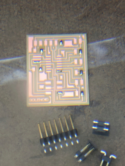
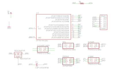
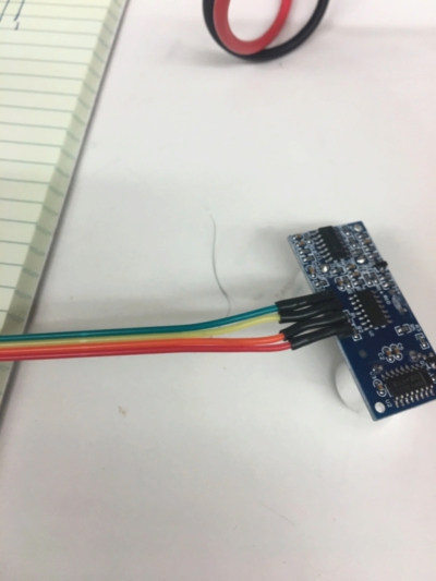
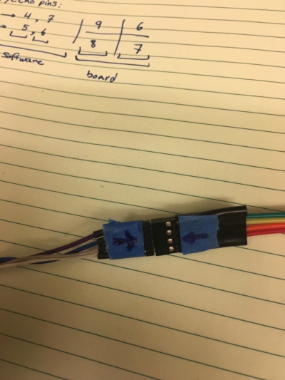
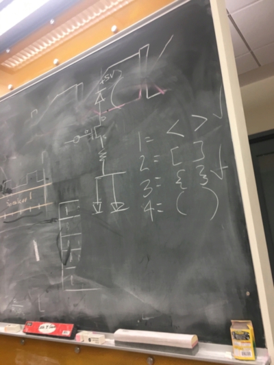
Next part was making the electronics. While Andrew worked on the speaker circuit, I shifted focus on making the solenoid part. The circuit had 3 types of interface. First it needed to receive input from multiple sonars, second it needed to send output to different solenoid board, and lastly it needed to communicate with other boards, over serial communication. We decided to use ATTINY 44 microcontroller, because of its size, price, and number of input/output that it provides. The first design of the board consisted of 3 2*2 pins. One used for communication with 2 sonars, one used for sending outputs to to solenoids, and last one was used for communication over serial.
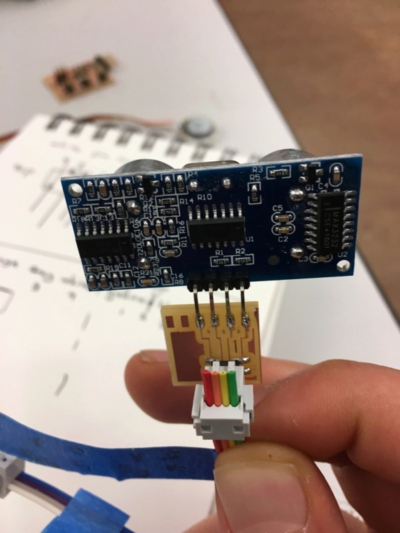
After designing and milling the board, I first tested the sonar function. I plugged the VCC and GND of the sonar backward by mistake, and realized after a couple of seconds, but it was already late, the reading that the damaged sonar gave me was rather interesting, it flipped on each iteration. With a new sonar however the reading was normal.Another observation was that if I completely block the sonar trig and echo components, the reading is always 0, as expected, but the rate of update is quite slow. This could be due to the way the code is structured. I also modified the putative solenoid pulse to be modulated by the distance reading of the sonar board.
#include
#include
#define RX  1
#define TX  0
#define Sol1 2
#define Sol2 3


byte Sol1State = LOW;
byte Sol2State = LOW;
unsigned long CurMS = 0;
unsigned long PrevSOl1UpdateMs = 0;
unsigned long PrevSOl2UpdateMs = 0;
const int Sol1ONms = 10;
const int Sol1OFFms = 40;

const int Sol2ONms = 10;
const int Sol2OFFms = 90;


SoftwareSerial Serial(RX,TX);
void setup() {
  Serial.begin (9600);
  Serial.println("Initializing...");
  pinMode(Sol1, OUTPUT);
  pinMode(Sol2, OUTPUT);
}

void loop() {

  CurMS = millis();
  //Serial.println(CurMS);
  updateSolenoid1();
  updateSolenoid2();
  //Serial.println(Sol1State);
  SwitchSol();

  }

void updateSolenoid1() {
if (Sol1State == LOW) {
   if (CurMS - PrevSOl1UpdateMs >= Sol1OFFms) {
      Sol1State = HIGH;
      PrevSOl1UpdateMs = CurMS;
   }
  }
  else {

   if (CurMS - PrevSOl1UpdateMs >= Sol1ONms) {
      Sol1State = LOW;
     PrevSOl1UpdateMs = CurMS;
   }
  }
 }

void updateSolenoid2() {
if (Sol2State == LOW) {
   if (CurMS - PrevSOl2UpdateMs >= Sol2OFFms) {
      Sol2State = HIGH;
      PrevSOl2UpdateMs = CurMS;
   }
  }
  else {
   if (CurMS - PrevSOl2UpdateMs >= Sol2ONms) {
      Sol2State = LOW;
     PrevSOl2UpdateMs = CurMS;
   }
  }
 }


// running solenoid
void SwitchSol() {
digitalWrite(Sol1, Sol1State);
digitalWrite(Sol2, Sol2State);
}

 void SwitchSol1() {
if (Sol1State == LOW) {
   digitalWrite(Sol1, LOW);
   Serial.println("low");
   }
  else {
    digitalWrite(Sol1, HIGH);
    Serial.println("High");
   }
}
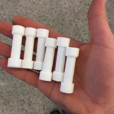
Next phase was making the solenoids. Last time we used the setup in EECS shop to make the solenoid wiring, we decided to make our own winding tool. we combined a hand drill,(one with extremely low speed for safety) and a holder to turn the solenoid based. We had leftover 3d printed pieces from output week and used it for testing. At first try we accidently use uncoated wire, that didn't work! but with coated copper we got about 20 ohms of resistance, and the field was enough to move the center part, but it was weak. Something that we decided to debug later. At this point we had two boards that worked to a reasonable degree and decided to do an evaluation and replanning of development of the project.
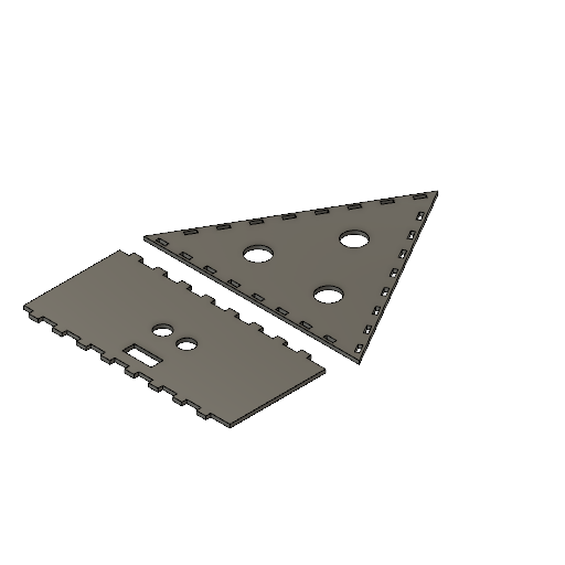
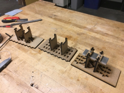
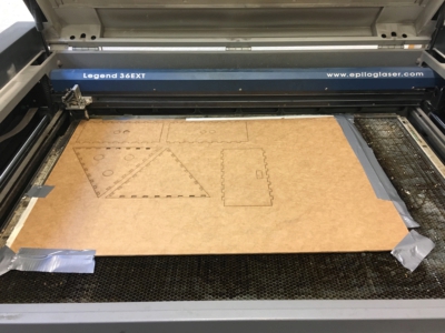
I decided to work on the design of the container and assembly of bars. Each piece had 3 walls, 2 of them had a sonar interface,and one had the interface slot. on top of the piece there were opening of attachment of the speakers and also hole for aluminum bars, and they all connected via press-fit. I first made the pieces out of cardboard. Surprisingly, the come out much better that I expected, the parts press fit together and were quite stable. Even though we initially thought of using wood and machine cut them, laser cutting suits our application and we decided to instead make pieces out of cardboard and MDF using the laser printer only.
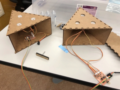
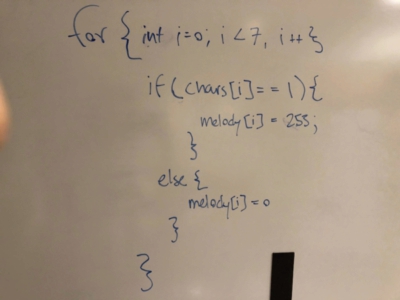
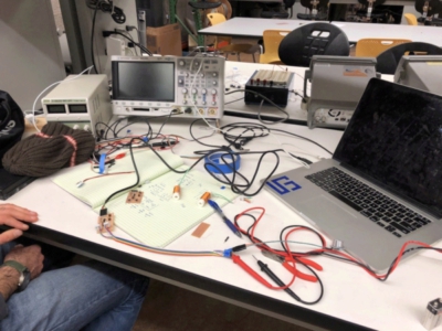
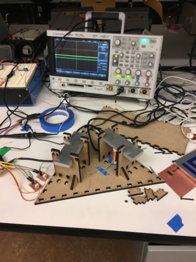
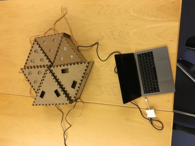
After laser cutting, we decided to work together more on the electronics. While I was focusing on the hardware, Andrew spent time on the software and used processing to sends characters to the board. We modified previous code to connect to different boards and use start and stop symbols to differentiate between each boards when communicating over serial bus. each packet of data contains a number bits that control which frequency to make for the sound board, which solenoid to activate in solenoid board. At the start and end of each packet different symbols are inserted to identify a board. For example, a packet for solenoid board has the following form : (10001001). the open and close parenthesis is recognizable by solenoid board and the sound boards ignore that particular packet of data. other symbols that were used are {},//. It took us sometime to debug and modify the code for both solenoid and sound board, as one issue was the rate the microprocessor was running. But after fixing the programmed worked reliably. We programmed the sonar to change the rate at which each sequence was played. The distance changed the time between each pulse by addition of extra delay. At this point I decided not to use the solenoid and instead see the signal to the solenoid on the oscilloscope.

#include
#define RX  1
#define TX  0
#define echoPin 7
#define trigPin 6
SoftwareSerial Serial(RX,TX);
int pauseBetweenNotes;
int Sol_1 = 2;
int Sol_2 = 3;

long distance;
const byte numChars = 32;
char receivedChars[numChars];
boolean newData = false;


void setup()
{
  //initialize serial communications at a 9600 baud rate
  Serial.begin(9600);
  pinMode(Sol_1, OUTPUT);
  pinMode(Sol_2, OUTPUT);
  pinMode(trigPin, OUTPUT);
  pinMode(echoPin, INPUT);

  establishContact();

}

void loop()
{
    recvWithStartEndMarkers();
    PlayNewSeq();
}


void recvWithStartEndMarkers() {
    static boolean recvInProgress = false;
    static byte ndx = 0;
    char startMarker = '(';
    char endMarker = ')';
    char rc;

    while (Serial.available() > 0 \ newData == false) {
        rc = Serial.read();

        if (recvInProgress == true) {
            if (rc != endMarker) {
                receivedChars[ndx] = rc;
                ndx++;
                if (ndx >= numChars) {
                    ndx = numChars - 1;
                }
            }
            else {
                receivedChars[ndx] = '\0'; // terminate the string
                recvInProgress = false;
                ndx = 0;
                newData = true;
            }
        }

        else if (rc == startMarker) {
            recvInProgress = true;
        }
    }

}

void showNewData() {
    if (newData == true) {
        Serial.print("This just in...");
        Serial.println(receivedChars);
         for(int i=0;i<8;i++){
            if (receivedChars[i] == '1'){
                 digitalWrite(Sol_1,HIGH);
                delay(50);
                digitalWrite(Sol_1,LOW);
                distance = calc_distance();
                delay(distance);
            }
            else{
                digitalWrite(Sol_2,HIGH);
                delay(50);
                digitalWrite(Sol_2,LOW);
                distance = calc_distance();
                delay(distance);
            }
          }
       newData = false;
    }
    else {
           for(int i=0;i<8;i++){
            if (receivedChars[i] == '1'){
                 digitalWrite(Sol_1,HIGH);
                delay(50);
                digitalWrite(Sol_1,LOW);
                distance = calc_distance();
                delay(distance);
            }
            else{
                digitalWrite(Sol_2,HIGH);
                delay(50);
                digitalWrite(Sol_2,LOW);
                distance = calc_distance();
                delay(distance);
            }
          }
    }
}

void PlayNewSeq() {
  while (Serial.available() <= 0) {
  Serial.println("A");   // send a capital A
  delay(300);
  }
}

int calc_distance()
{
  long duration, distance;
  digitalWrite(trigPin,LOW);
  delayMicroseconds(2);
  digitalWrite(trigPin,HIGH);
  delayMicroseconds(10);
  digitalWrite(trigPin,LOW);
  duration=pulseIn(echoPin,HIGH);
  distance = duration/10;
  return distance;
}
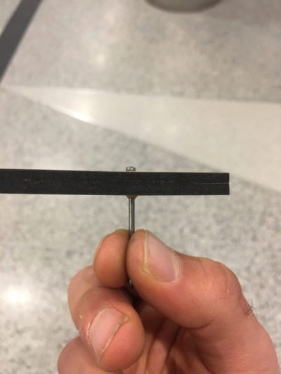
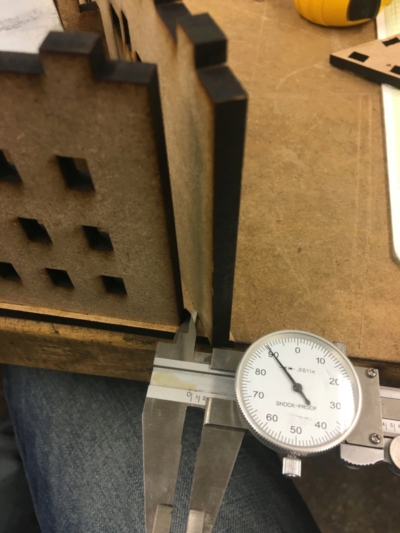
I next switched back to hardware design. Andrew designed the solenoids and we used 3d printer to make them. The design of the solenoid box was more involved than I expected give that the bars were too big to fit in the sound box, and they needed to mounted in such a way that they resonate correctly. I went through multiple rounds of testing and modification (inspired by spiral development process) to optimize the holding mechanism. One thing that I tried to do but didn't work was using nails to hold the aluminum from the side or top and bottom, but the MDF did not have enough structural integrity on the sides. instead I put cover on the top of the bar that could be used for putting a nail and containing the aluminum. The pressfit poles also did not have endurace to weight, and I put extra helpers to stabilize them, I tried similar construction for "make something big" week and it help in figuring out how to do it reliably. One additional thing that I didn't notice in the first design was the overlap between walls that touch on on of the vortex, and the first construction ended up having a gap, or overlap, but after fixing worked. We saved the first design but sanding away the extra MDF.
After ensuring that the construction of the boxes are reliable and scalable we returned to the electronics and more programming. I decided to redesign the board and separate the power and signal on the board. the sonar interface was powered via the board, but the solenoid interface had to be powered separately given the previous test on output week. Each solenoid box had two solenoid, and each one used up to 200 amp per pulse from the board. the first test ruled out the feasibility of using the power of the network to run all the boards, so I decided to use additional power source. the first designed that I made relied on a battery to power the device, but it didn't move the solenoid reliably enough to drive them. as the first fix I modified the movement mechanism of the bar inside the solenoid. Initially the bar had a magnet in one end that was inside that solenoid and a force applied to it to move it. I additional fixed to permanent magnet with opposite polarity in the bottom of the solenoid to make the bar float. This made the bar move more freely, but didn't completely solve the problem. I also tried winding more copper to increase the efficiency of the push from magnet.
Facing with this problem I went through debugging the circuit using a combination of reading manuals, what people did before, and testing new parts and making measurement. I realized that debugging is an "informed exploration". It requires reading out the outputs and inputs to the solenoid power board when it was connected to the solenoid board, measuring the resistance of components, function of the N-MOFSET, and the flyback diodes. I decided to minimize the variable that can cause the error by using the external power source, making the program to only send a pulse to one solenoid, and making measurement of the solenoid with oscilloscope. By doing this I realized that the N-MOSFET is not switching from OFF to ON when the pulse is received from the board. After changing the N-MOSFET, the board came back to life! After solving the problem, I used external power to run each solenoid board, and were able to have a functional unit with 2 solenoids.
At this point we decided to scale up and make more boxes. Andrew made more sound boxes, and I made a second solenoid box. Contrary to I expected, making a duplicate was quite fast, and instead took about 3 hours to make a fully functional box. Lastly we packaged the electronics, mechanical parts and wiring inside each box, and program each of them with a unique identifier for serial communication. The final design produced what we expected and it was quite satisfying to see them working together.
Presenting the work to the class and in the open house was on its own an interesting experience. Talking to other students in the class about the design, the problems that we ran into, and how we solved them, and how they would have solved it was a good learning experience. In the open house people were excited to see them working and had interesting suggestions on how it might be extended to incorporate new inputs and output.
Bill of Materials
| Item | Quantity | Source | Price per unit | Total price |
|---|---|---|---|---|
| ATTiny 44a | 8 | FAB | $1.18 | $9.44 |
| FTDI header pins | 18 | FAB | $3.19 | $57.42 |
| Resistors | 30 | FAB | $0.01 | $3.00 |
| Capacitors | 12 | FAB | $0.07 | $8.4 |
| Cardboard | 6* (24'*20' sheet) | FAB | $1.50 | $9.00 |
| Speakers | 20 | FAB | $0.59 | $11.8 |
| 5v power adaptor | 2 | Personal | $6.85 | $13.70 |
| Aluminum sheet | 1*(10'*10') | Personal | $13.55 | |
| MDF-sheet | 2*(24'*20') | Personal | $4.00 | $8.00 |
| Sonar | 8 | Fab | $8.99 | $71.92 |
| N-MOSFET: | 6 | Fab | $1.13 | $6.78 |
| schottky diode | 6 | Fab | $0.17 | $1.02 |
| pins headers 2*2 | 20 | Fab | $0.66 | |
| pins headers 2*3 | 6 | Fab | $0.60 | $13.2 |
| Wires | approx 12 feet | Fab | N.A | |
| 20Mhz resonator | 8 | Fab | $0.43 | $3.44 |
| Total | $231.33 |