Jaclyn Berry
Final Project Update
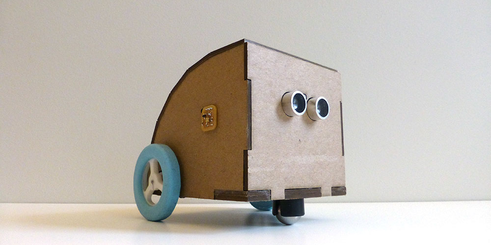
Gowi
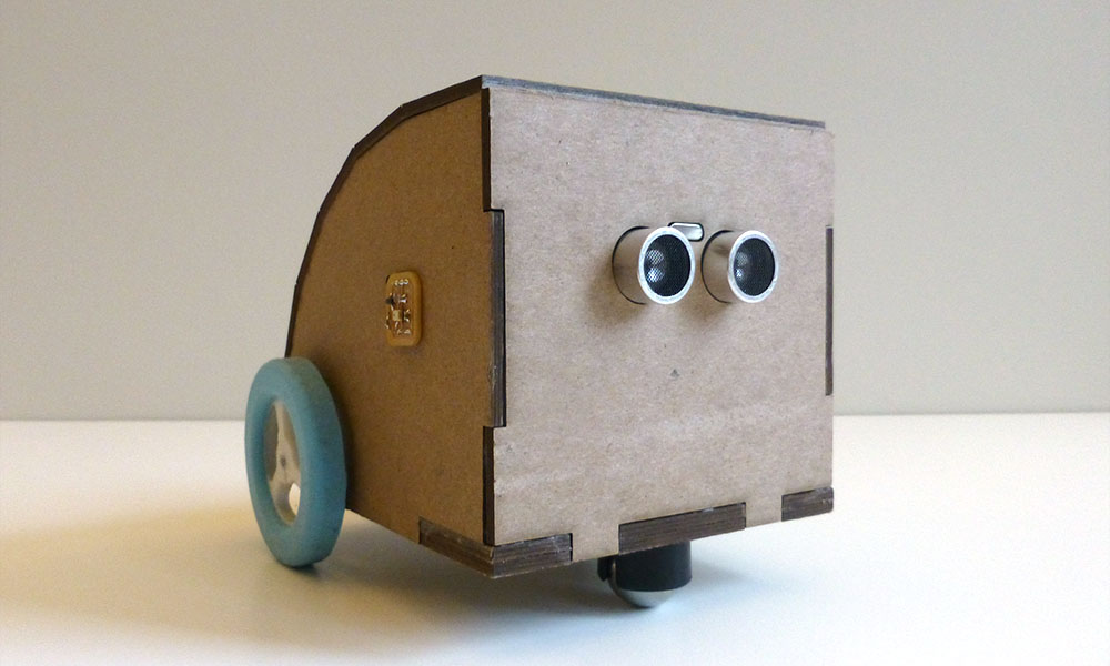
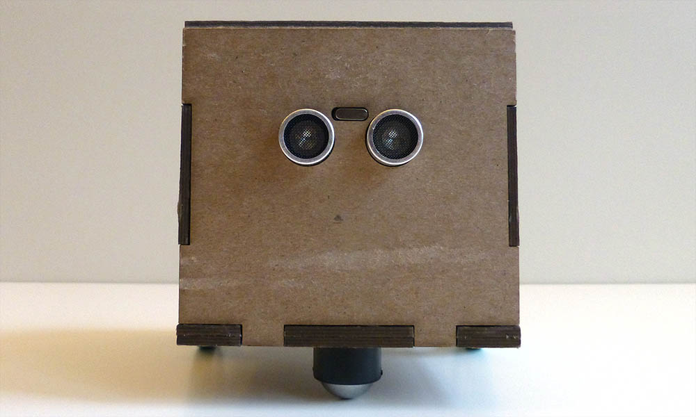
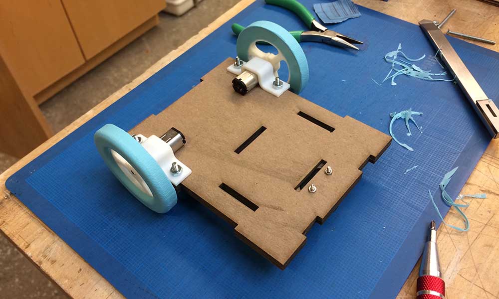
Meet Gowi, the antisocial robot that runs away from loud noises—and sometimes itself. Gowi uses two analog microphones to detect loud noises on either side of its body. Gowi also uses an ultrasonic range finder to detect objects close to its face.
See Gowi scuttle.
Precedent Work
Gowi is the antithesis to social robotics. Some work on social robotics includes:
- Jibo
- Personal Robots Group (MIT)
- Miklósi, "On the Utilization of Social Animals as a Model for Social Robotics," 2012
Gowi's interactions can be viewed as simplified animal behavior. Some previous work on animal behavior in robotics includes:
- Anderson, "Animal Behavior as a Paradigm for Developing Robot Autonomy", 1990
- Webb, "What does robotics offer animal behavior?", 2000
And maybe in the future, Gowi could adopt some of the methods used for adaptive behavior and reinforcement learning.
Final Bill of Materials
| Item | Quantity | Price | Vendor |
|---|---|---|---|
| ATmega328p | 1 | $2.00 | Digi-Key |
| ATtiny84 | 1 | $0.86 | Digi-Key |
| PIN HD (Male SMT RA 1x6) | 2 | $0.60 | Digi-Key |
| PIN HD (Male 2x2) | 5 | $0.52 | Digi-Key |
| PIN HD (Male 2x3) | 5 | $0.83 | Digi-Key |
| PIN HD (Male 2x5) | 1 | $0.80 | Digi-Key |
| PIN HD (TH Male 1X3) | 2 | $0.66 (1x40) | Digi-Key |
| CONN IDC SOCKET (Female 2x2) | 8 | $0.73 | Digi-Key |
| CONN IDC SOCKET(Female 2x3) | 5 | $0.80 | Digi-Key |
| CONN IDC SOCKET(Female 2x5) | 1 | $0.48 | Digi-Key |
| 3.3V Regulator, 100mA | 2 | $0.70 | Digi-Key |
| 5V Regulator, 1A | 1 | $0.50 | Digi-Key |
| LED 1206 | 3 | $0.34 | Digi-Key |
| 16 Mhz Ceramic Resonator | 1 | $0.50 | Digi-Key |
| 20 Mhz Ceramic Resonator | 1 | $0.63 | Digi-Key |
| Push Button | 1 | $1.06 | Digi-Key |
| Analog Microphone | 2 | $2.04 | Digi-Key |
| Ultrasonic Range Finder | 1 | $2.00 | Amazon |
| H-Bridge Motor Driver | 2 | $1.95 | Digi-Key |
| Resistors - 10k | 2 | $0.10 | Digi-Key |
| Resistors - 1k | 6 | $0.10 | Digi-Key |
| Resistors - 0 Ohm | 2 | $0.10 | Digi-Key |
| Capacitors - 0.1uF | 11 | $0.25 | Digi-Key |
| Capacitors - 1uF | 1 | $0.25 | Digi-Key |
| Capacitors - 10uF | 6 | $0.25 | Digi-Key |
| JST-PH PIN HD | 2 | $0.58 | Digi-Key |
| 3.7V - 2000mAh - Lithium Polymer Batt | 2 | $13.96 | Amazon |
| Pololu Gearbox Motor: 200 RPM< 6V | 2 | $17.95 | Pololu |
| Metal Ball Caster | 1 | $4.95 | Adafruit |
| 30"x40" 3-ply Chipboard | 1 | $8 | Blick |
| 4-40 Screws - 1/2" | 4 | $0.15 | Blick |
| Total Cost | $122.37 | (Excluding Shipping) |
What I Made
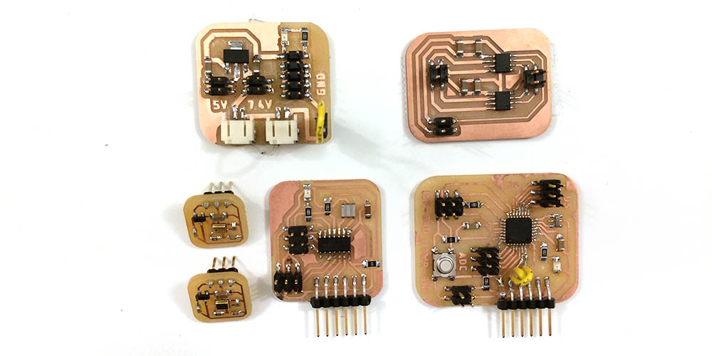
I made almost all of the parts in Gowi. That includes:
- ATtiny44 Board
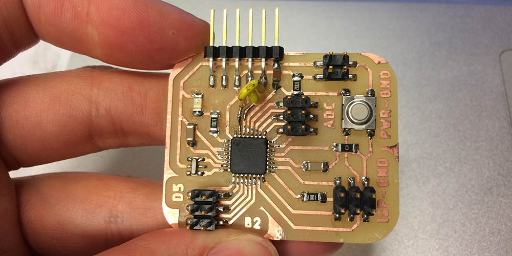
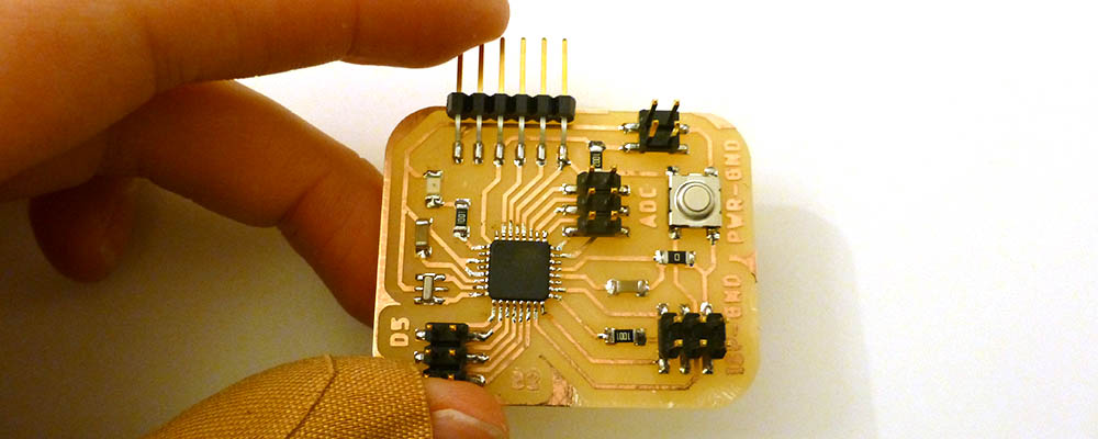
- ATmega328p Board
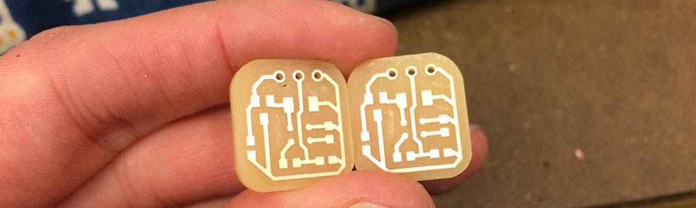
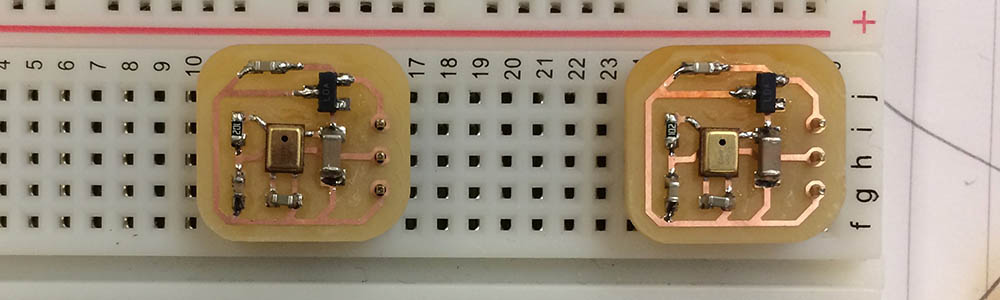
- Microphone Breakout Boards
- Power Distribution Board
- H-Bridge Breakout Board
- Wheels and Tires
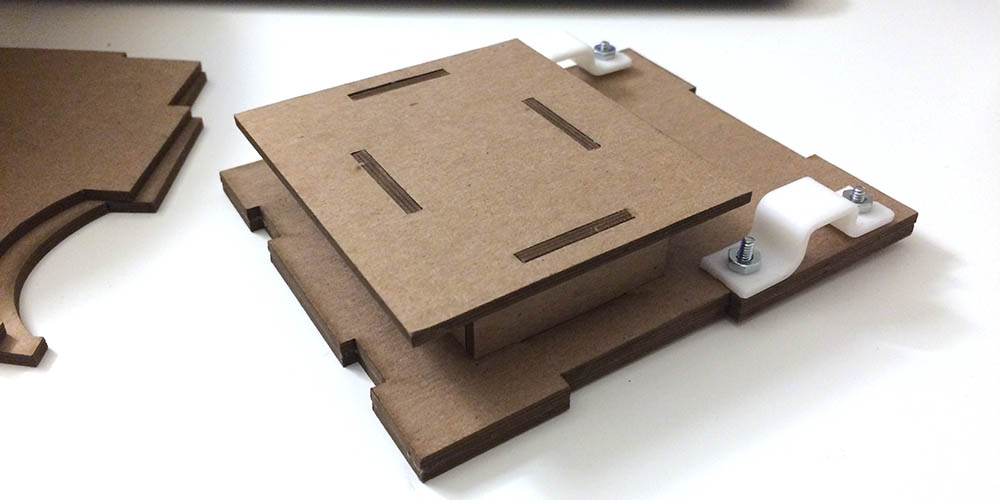
- Motor Clamps
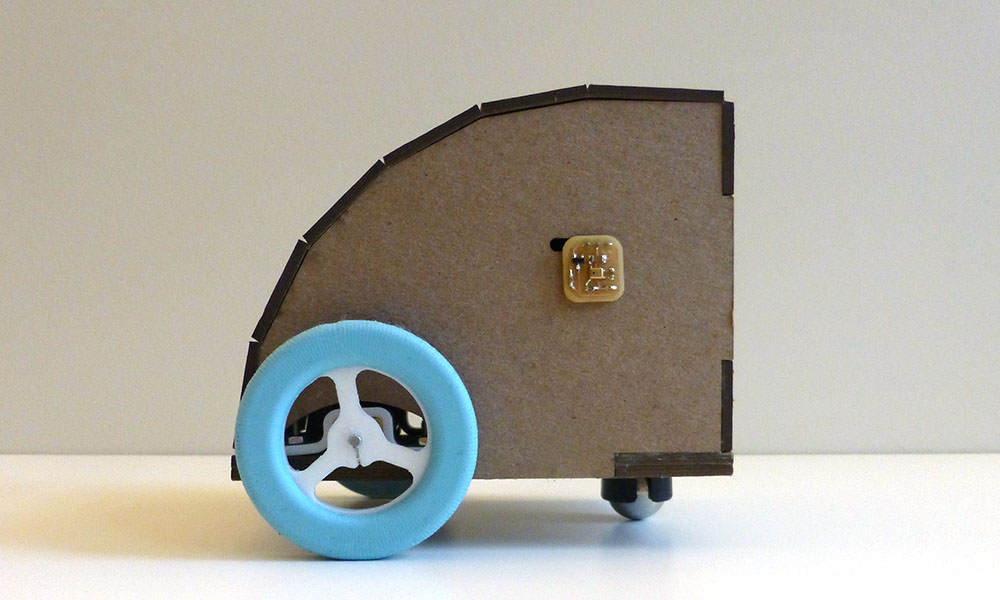
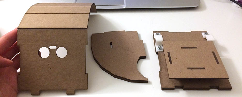
- Gowi's Body
What Questions Were Answered?
I had three motivations for building Gowi: 1) how do I make a robot, 2) can I use motors to make something cool and, 3) how can I use microphones as an input system for an interactive device.
How do I make a robot?
As it turns out, this is really fun and complicated. I learned that robots have A LOT of parts to them. Even a simple amateur robot like Gowi took considerable time to design the chassis, wheels, electronics, interaction, and software. Of all the steps, I think designing the interaction in software was the most difficult. This time around, I used Arduino, but I hope to use embedded C in my next endeavor.
How can I use motors to make something cool?
The possibilities are infinite! My choice was to make a robot, but my section-mates chose to use motors for other operations like making seat imprints, controlling extruder heads, etc.
How do I use microphones as an input system?
This question was particularly important to me. I struggled to use microphones in the past because I did not understand how to process the signal and I did not understand how sampling worked. Fortunately, I took this class as an opportunity to figure them out. With the help of Will and Neil's demo files, I learned how to do some very simple signal processing in software. I learned for something so dependent on timing/frequency as sound, you pretty much need to have a microcontroller with a fast sampling rate dedicated to processing that signal. So, I not only learned about microphones, but I also learned about networking. And networking, as I found out, can mean wired OR wireless. While I still find microphones a bit tricky to use, I am now confident that I can use them!
ALL THE STUFF THAT NEEDS TO HAPPEN
Get power board working. Add an on-off switch.Get 1 microphone working with attiny44Get 2 microphones working with attiny44Get attiny talking to 328pGet 328p working with motorsGet 328p working with range finderGet 328p working with range finder and motorsGet 328p working with range finder, motors, and attiny44Design WheelsDesign Wheel MoldMill Wheel MoldFabricate wheel hubsCast WheelsDesign Robot BodyLasercut robot bodyPut Everything together- Make sure it works.
update 12/18/2017
Today was dedicated to figuring out the software component of Gowi. Special thanks to Grace for helping me think through the pseudo code before I dove into this task. The microphones were figured out and now all that was left was the motor interaction and the distance sensor. It took a lot of trial and error, plugging and unplugging, but eventually I got something reasonable. As a short summary, Gowi checks if objects are within 50 cm of his face (this part is a bit rough), if not he checks for loud sounds on the left or right (communicated through UART), then he turns in the opposite direction. When there are no loud sounds, Gowi will randomly inch forward or stay still. If there is an object in front of his face, he'll back up really fast. Here's the code I uploaded to the 328p:
/*
 * PINOUTS FOR ARDUINO PRO MINI
 */

// PWM pins 5,6,9,10
#define ledpin 3
#define mot1a 5
#define mot1b 6
#define mot2a 9
#define mot2b 10
#define RFtrig A3
#define RFecho A2

//for DSP
float oldVal = 0;

//for PWM
int SPEED = 100;

//starting
bool start = true;

void setup() {
  pinMode(ledpin, OUTPUT);
  pinMode(mot1a, OUTPUT);
  pinMode(mot1b, OUTPUT);
  pinMode(mot2a, OUTPUT);
  pinMode(mot2b, OUTPUT);
  pinMode(RFecho, INPUT);
  pinMode(RFtrig, OUTPUT);
  randomSeed(analogRead(A0)); //init random number
  Serial.begin(9600);
}

void loop() {
  // put your main code here, to run repeatedly:
  if (start){
    delay(5000);
    start = false;
  }

  char dir;
  float duration, distance;
  digitalWrite(RFtrig, 0);
  delayMicroseconds(2);
  digitalWrite(RFtrig, 1);
  delayMicroseconds(10);
  digitalWrite(RFtrig,0);

  duration = pulseIn(RFecho, 1);
  distance = (duration/2)*0.0344;

  float filtered = LowPass(distance);
  //Serial.println(filtered);

  //If something is close by, back up
  if (filtered < 50.0){
    REVERSE();
  }

  //Otherwise do your spinny thing.
  else{

    if (Serial.available()){
     dir = Serial.read();
    }

    if (dir=='R'){
      digitalWrite(ledpin, HIGH);
      LEFT();
      delay(50);
    }

    else if (dir == 'L'){
      digitalWrite(ledpin, LOW);
      RIGHT();
      delay(50);
    }

    //otherwise random wander
    else{
      int randNum = random(10);
      if (randNum%4 == 0){
        FORWARD();
        delay(20);
      }
      else{
        STOP();
        delay(50);
      }
    }// end random wander
  }// end spinny thing
} //end loop


void STOP(){
  analogWrite(mot1a,0);
  analogWrite(mot1b, 0);
  analogWrite(mot2a, 0);
  analogWrite(mot2b,0);
}

void RIGHT(){
  analogWrite(mot1a,0);
  analogWrite(mot1b, 0);
  analogWrite(mot2a, 0);
  analogWrite(mot2b,SPEED);
}

void LEFT(){
  analogWrite(mot1a,SPEED);
  analogWrite(mot1b, 0);
  analogWrite(mot2a, 0);
  analogWrite(mot2b,0);
}

void FORWARD(){
  analogWrite(mot1a,SPEED);
  analogWrite(mot1b, 0);
  analogWrite(mot2a, 0);
  analogWrite(mot2b,SPEED);
}

void REVERSE(){
  analogWrite(mot1a,0);
  analogWrite(mot1b, SPEED);
  analogWrite(mot2a, SPEED);
  analogWrite(mot2b,0);
  delay(5);
}

float LowPass(float val){
  float eps = 0.98;
  float filterVal = oldVal*eps + val*(1-eps);
  oldVal = filterVal;
  return filterVal;
}
And the code I uploaded to the attiny84 to process the sound:
/*
 *For an ATtiny84 with a 20mhz external clock.
 */

#include
#define mic1 2 // LEFT
#define mic2 3 // RIGHT
#define ledpin 8
#define Tx 1
#define Rx 0

SoftwareSerial mySerial(Rx,Tx);

//smoothing vars
float sound1[8]={}; // raw sounds
float sound2[8]={}; // raw sounds

//define base sound
float base1;
float base2;

//define init toggle
bool iTog = true;


void setup() {
  // put your setup code here, to run once:
  pinMode(mic1, INPUT);
  pinMode(mic2, INPUT);
  pinMode(ledpin, OUTPUT);
  pinMode(Tx, OUTPUT);
  pinMode(Rx, INPUT);
  mySerial.begin(9600);
}

void loop() {

  // Process the sound
  //shift baseline val to zero, then correct for negative amplitude.
  float newSound1 = analogRead(mic1); // LEFT
  float fSound1 = processSound(sound1, newSound1);

  float newSound2 = analogRead(mic2); // RIGHT
  float fSound2 = processSound(sound2,newSound2);
  /*
  mySerial.print(fSound1);
  mySerial.print(",");
  mySerial.println(fSound2);
  */


  int diff = 8;
  if (fSound2>diff && fSound2>fSound1){
    mySerial.write('L');
    //mySerial.println('L');

  }
  else if (fSound1>diff && fSound1>fSound2){
    mySerial.write('R');
    //mySerial.println('R');

  }

}

float processSound(float oS[], float nowSound){
  //oS = original signal, fS = filtered signal
  oS[7] = nowSound;
  //moving average
  float movAvg = getAvg(oS);
  //high pass filter
  float filtered = abs(nowSound-movAvg);
  // get ready for next value
  shiftArray(oS);

  return (filtered); //filtered^2
}


//moving average filter
float getAvg(float nums[8]){
  float thesum=0;
  for (int i=0; i<8; i++){
    thesum+=nums[i];
  }
  thesum/=8;
  return thesum;
}

//shift values in array back 1
void shiftArray(float nums[8]){
  for (int i = 0; i<7; i++){
    nums[i] = nums[i+1];
  }
}
The troublesome part about the code for the range finder had to do with timing. The range finder signal is smoothed using a moving average, low pass filter. However, due to the delays() in the code to accomodate motor movement, the moving average isn't always up to date with the realtime measurements. I made a quick fix for this problem by increasing the threshold for "close" values. But in reality, I probably should have put the range finder on its own microcontroller and called an interrupt routine. The sound interaction would also be improved by using an interrupt routine, but that's for the next round of edits.
update 12/17/2017
Still working on microphones interfacing with motors. I had some trouble with "calibrating" the microphones to a baseline condition. I went through two possible solutions.
First solution was collecting 10 seconds of baseline sound conditions and comparing the signal to the baseline. I had trouble with ints/floats/longs, but Ali and Sean helped me figure that out. This solution was a bit limited and not super functional... I could not easily tell the difference between the loud sounds on the right and the left, and there were no, "quiet" moments.
The second solution was a suggestion from Will. I used a high pass filter on my moving average function to show only the "spikes" in volume. This solution worked great because it allowed for quiet moments and loud events. The loud events trigger the motors to spin. It also took up way less memory.
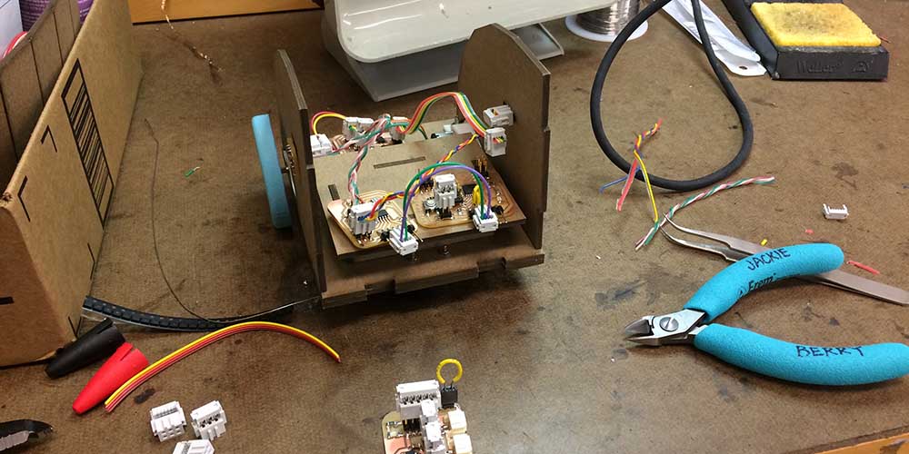
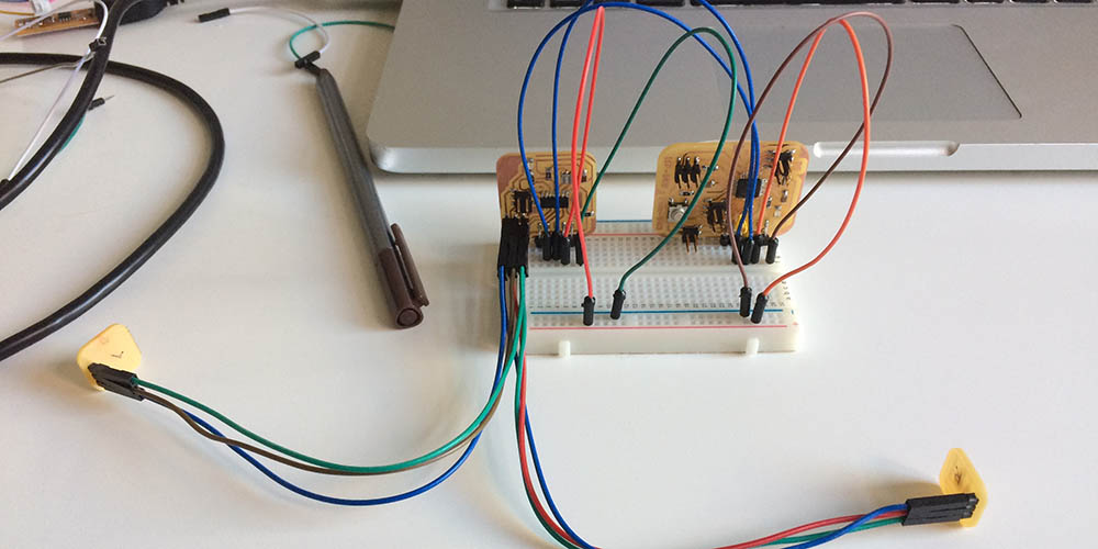
The wiring got to be very overwhelming. I spent several hours trying to make a cleaner system. It's still a bit chaotic, but at least it's easier to hook things up together. I was worried about the power distribution board getting too hot (I think from the motors pulling a lot of current), so I added a really thick power wire between my high voltage output and the h-bridge vbb input. It seems to have helped with the heat.
I got the robot moving. I think the motors were too loud for the sound reactive system to work very well. I'm going to implement PWM tomorrow to run the motors at 50% power -- I think it will be a bit quieter and easier to demonstrate the sound reactivity. In the meantime, I have to fix a few of my solder joints and make a new cable to accomodate PWM.
Last thing on the list is to add the range finder.
update 12/16/2017
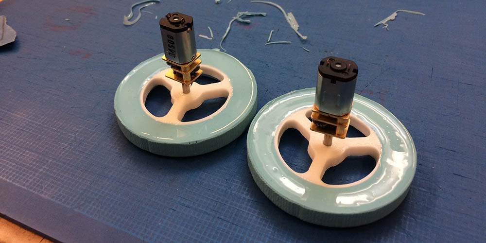
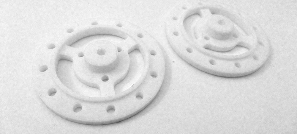
Wheels came out pretty good! aaaaand... good news, THEY PRESS FIT! IT'S A MIRACLE!
After wrestling with the pin assignments in Arduino, I got my robot moving as well. A good thing to note, these H-Bridges are very fussy about the power source. Kyle, Calvin and I tried to debug why Kyle's H-Bridges were not working. We found out that the power source was too low voltage. Kyle's batteries were only 6.4V, mine were 7.4V. The H-bridge datasheet says it takes a minmum of 8V for the supply side. I cut that one a bit close!

I tried to get my sound working. It turns out signal processing takes a lot of brain space, so I had to replace my attiny44 with an attiny84. I applied some smoothing filters to the sound signals (moving maximum and moving average) over a window of 10 samples. But I wasn't seeing a huge discrepancy between "quiet" and "loud."
I tried amplifying the signal by a factor of 2. But that uniformly scaled the whole signal. So I tried squaring the signal and that seemed to help elaborate the relationship between "quiet" and "loud."
Next, I really needed to collected baseline readings to calibrate each microphone for a given environment.
update 12/15/2017
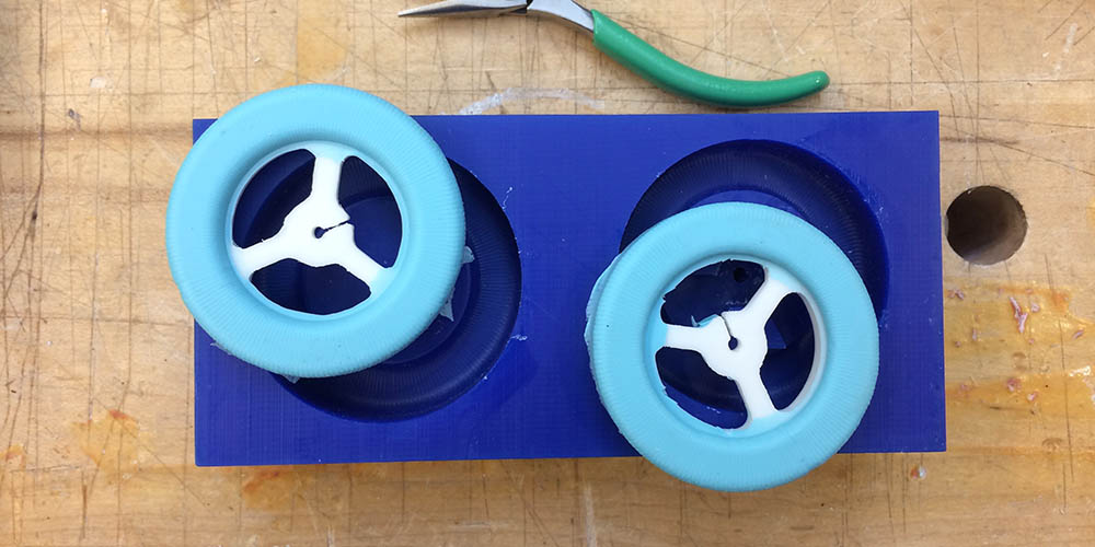
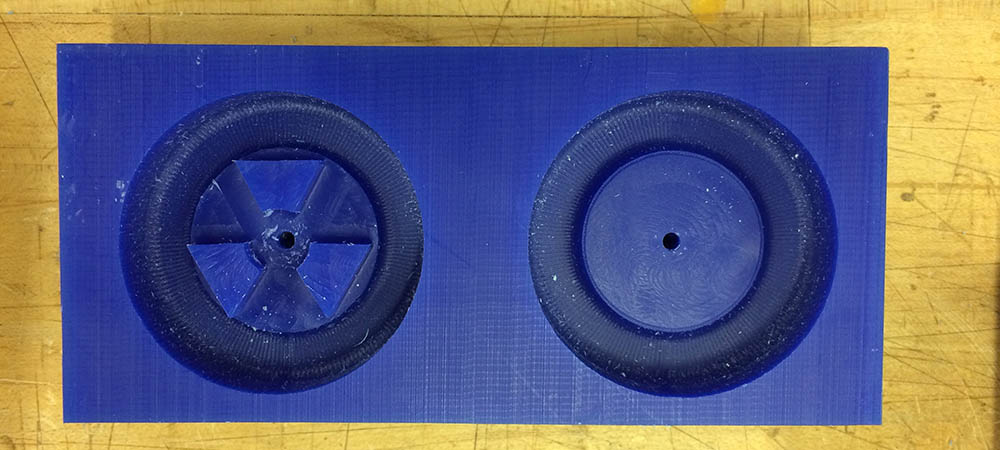
Justin helped me set up my mastercam file for my new wheel mold. I used a radial rough cut shallow finish cut with the 1/4" ball endmill. Then I finished the tire treads with a radial finish cut with a 1/8" ball endmill. I did the tool change almost completely by myself and feel much more comfortable using the shopbot.
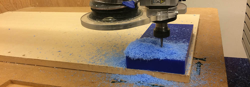
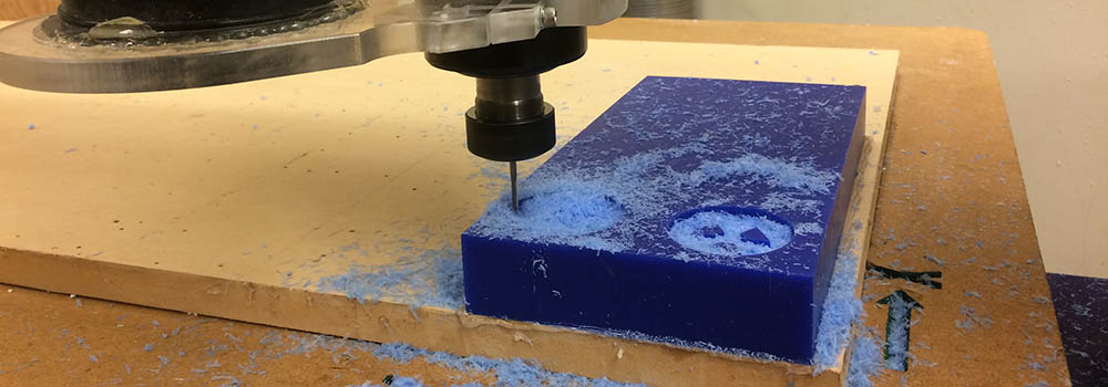
The mold came out great. I had to shave a bit of the registration "pegs" to get my wheel hubs to fit in the mold.
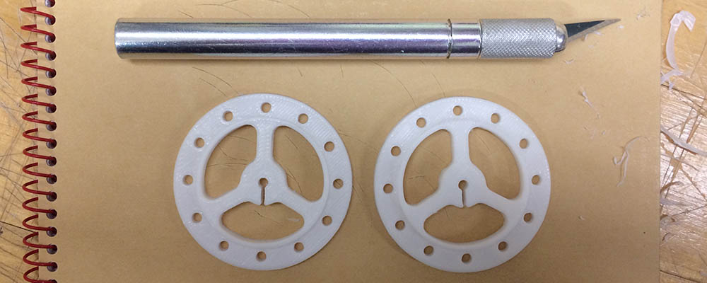
3d printing was a bit of a nightmare this week. Soma helped me do a testprint for what size hole would fit over my axles (all the printers in the archshop were occupied at the time). Kyle shared some of pololu's wheel model files with me. I tried to adapt their press fit design to my own wheels with little success. It's surprisingly hard to make 3d print parts press fit to metal rods. It took me several tries to get a decent print of a mostly functional hub. On one of my prints, the raft adhesion layer completely fused to my print, so I had to scrap it and start again.
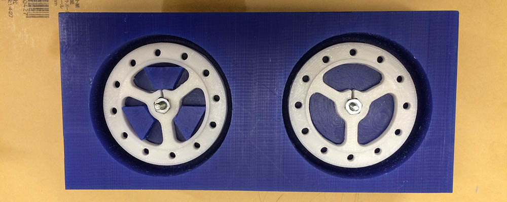
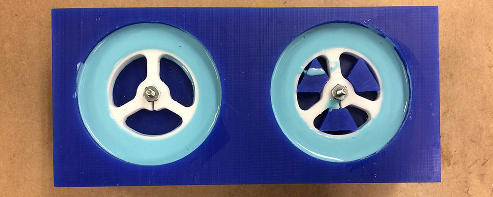
I cast the tires around my 3d printed hubs with oomoo. It didn't come out quite as tidy as I hoped, but that's how it goes.
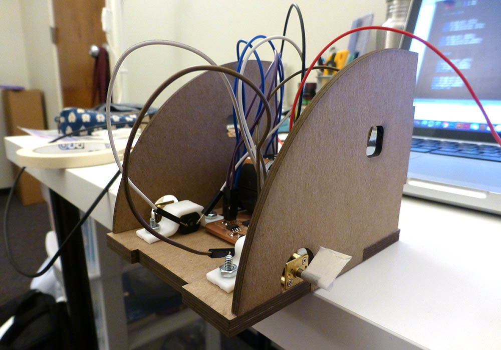
I designed my robot in Rhino this time (saved me some time...) and lasercut my robot body. The only challenge was getting the crystal oscillator to fit in the hole on the face of the robot. I finally got it to work after three tries.
update 12/13/2017
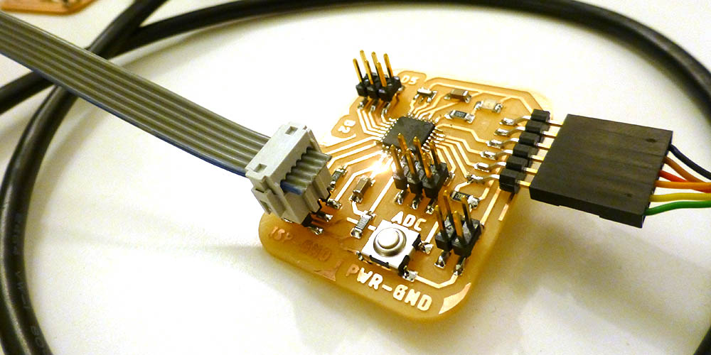
328p is now working although cannot be directly programmed from Arduino. Earlier I had crossed Tx and Rx and forgotten a capacitor near the FTDI reset pin. Once I trimmed and resoldered those aspects, programming and serial communication worked fine.
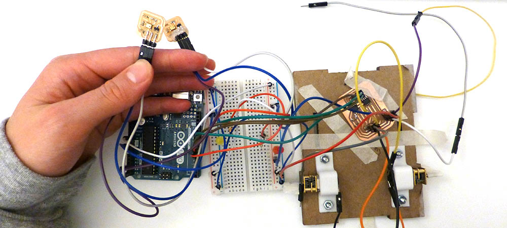
I made new microphone boards with through-hole connectors. I'm planningn to attach the microphones to the outside of my robot and have the headers stick through small holes to the inside of the body. I'm actually very proud of these microphone boards... and they work. Tested and everything.
I made a master battery power board. The board takes two 3.7V LiPo batteries to supply 7.4 volts to my motors (I know they're only rated for 6, but it should probably be ok... 6 AA batteries didn't seem to kill them.) But of course... A PROBLEM arised!
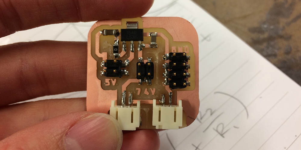
Looks like the voltage regulator I got from the shop does not mach the regulator from the inventory and therefore, I was following the wrong datasheet. I looked up the part number on the component directly and it looks like it might be a Texas Instruments regulator with different pinouts. I will debug in the morning.
update 12/09/2017 -- 12:00AM
I milled a new board this week. It was lovely. But it didn't quite work (surprise!)...
Debugging the 328p
I tried to program the 328p in Arduino, successfully burned bootloader for the Arduino Pro Mini (328p, 16mhz). But I couldn't upload a program! I compiled hex from arduino and tried to upload via usbtiny isp and it worked! So there was something weird going on...
I tried getting serial to work next. I compiled the code from arduino then uploaded to the 328p via usbtiny/isp. Uploading was fine. When I opened the serial terminal, nothing showed up. I tried the code on my Arduino uno, and nothing was wrong there. So I tried crossing my tx/rx lines between the ftdi and the 328p and left off the reset pin. This got the board talking to the computer! It turns out that you connect Rx from the 328p to Tx on the FTDI and vice versa.
Next, I was curious of the reset pin was causing trouble with the programming. While the serial communication was going, I connected the reset pin to the ftdi cable, and everything stopped. This was the source of a problem. I referred to Neil's hello.world board for the 328p and noticed that he had a capacitor between reset, vcc, and reset-ftdi. My board is missing that.
Tomorrow there will be much board sugery.
update 11/28/2017
Successes and failures this week. After successfully getting the 16u2 to talk to usb, and while waiting for a new usb cable to come in the mail, I programmed my 16u2 with ISP headers, and my computer stopped seeing the 16u2. I spent a lot of time trying to find information in the datasheet, saw something about the UDCON register defaulting to DETACH on reset, so D+ was pulled low. I probed with my multimeter and it was pulled low, but disabling detach did not activate the pullup resistor. It might be time to try a different microcontroller.
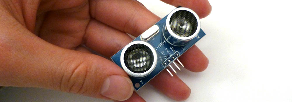
I found out that the time of flight sensors use i2c communication protocol, which the 16u2 does not support. So I switched to an ultrasonic distance sensor.
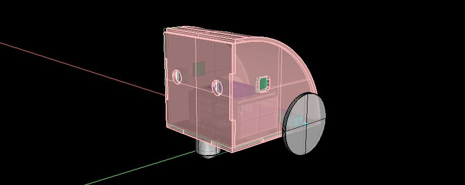
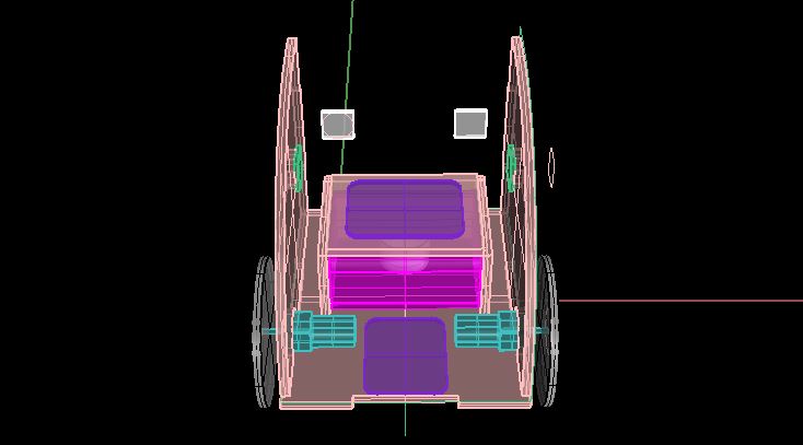
I made my first revision model of the whole robot. I used Rhino this time to make it a bit faster. For the next version I think I will use Fusion.
I printed some new wheel hubs. The holes were too small for pressfit. I think if I updated them to 1/8" diameter they will print at the perfect diameter (slightly under). I want to learn FusionCAM to mill out the molds for my tires.
I fabricated the first version of my robot chasis out of chipboard. I'm actually very happy with this material choice. I think I may need to make it slightly larger, becase the parts were a bit cramped. Unfortunately, I'm very dependent on fasteners for this design. I will need to find some very tiny screws for the distance sensor.
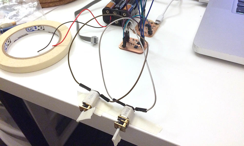
I started testing out how to use the microphones to control the motors. I got it partially working, but not very well. I think I will need to smooth the signal again like I did in the wk12 homework assignment. I'm worried about programming this entire interaction in C directly. Pardon the wires while I try to figure this out...
update 11/23/2017
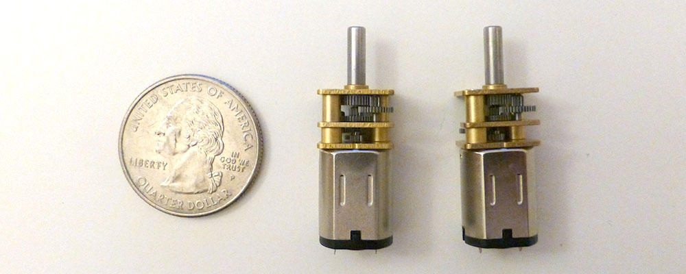
Many things have developed over the past month. To start I purchased some tiny motors. I didn't expect them to be this small, but since they were a little expensive, I'm hoping that they will work just as well. They are 1:150 gear ratio, 200 RPM, 6v DC motors.
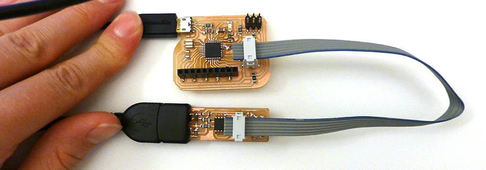
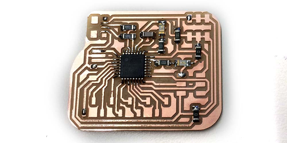
I started making a board for the atmega16u2. I chose this board for it's many pins, and capability to program via usb cable. Unfortunately, I have not been able to program it through usb as of yet. I can program it fine through the ISB header and the usbtiny fortunately.
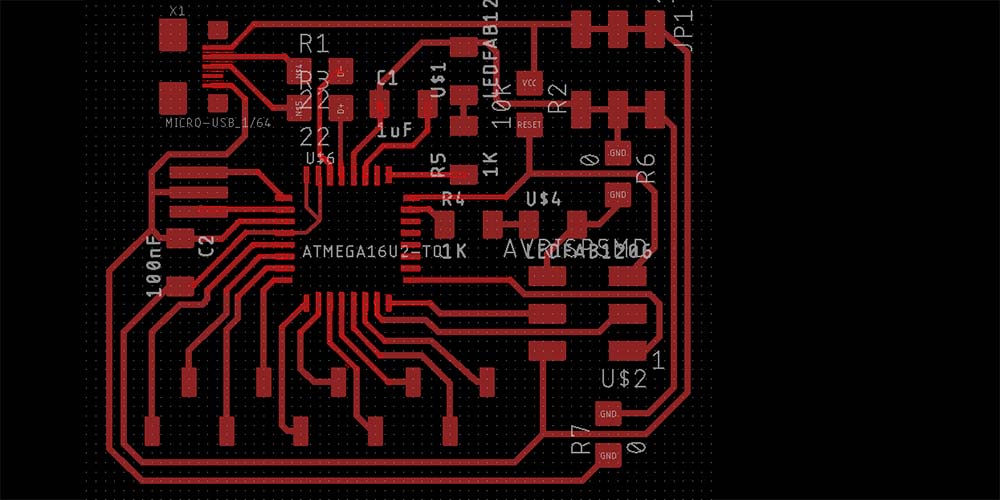
I milled it out on the SRM-20 with the 1/64" endmill. I had to trick mods into thinking the endmill was 0.013" for it to complete the teeny tiny traces by the micro usb header. It was a bit risky and the traces did start to peel up, but everything seems to have come out ok. Next time I think I need to use a new endmill because some of the traces looked jagged.
I designed the board to have breakout pins just like an Arduino so I could easily test out my input/output devices with it. Some design changes I will implement in the next iterations: labels would be nice, a power indicator LED, more breakout pins, mounting holes, maybe a reset button. And of course USB functionality. (Thank you to everyone who has helped me troubleshoot this board so far: Will, Jonah, Amanda and Tomás).
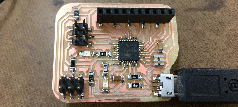
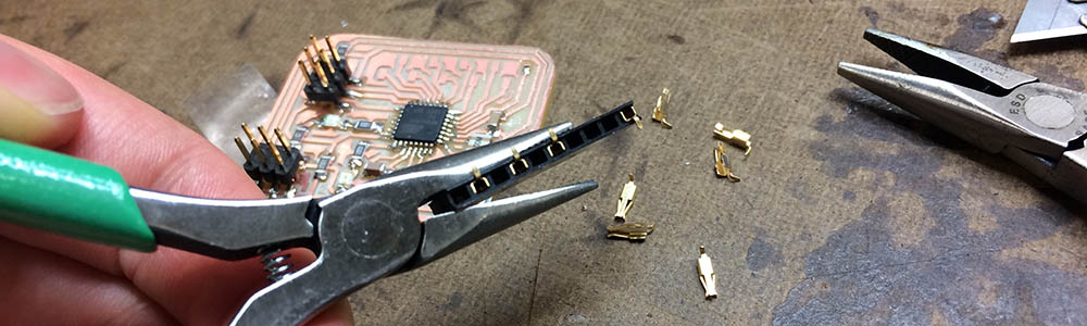
One funny aside–I drew up the eagle package for the 10 pin female headers, but I accidentally mirrored the footprint. I realized this mistake when I had to solder the header on. Instead of milling a new board, I found out you could pull out the "feet" of the female headers and turn them 180 degrees. This worked like a charm. I will have to fix my package in eagle later.
I realized this microcontroller isn't set up for Arduino yet, so I had to grit my teeth and start building my program in C. I started from Neil's motor example code, which worked great for the normal 12V DC motors, but didn't seem to work for my motors. I found out it was related to the PWM rate, but I haven't fully troubleshooted the motor control yet.
In tangential news, I started building a simple model for my robot to visualize how all the pieces will go together. My first prototype will be built out of cardboard and wood or acrylic. We'll see how far we get after that.
The sensing devices have changed for my robot as well. I've decided to use sound levels (volume) as the trigger for my anti social robot. I tested out some microphones (week11) and still need to build a board for the distance sensors. I will also need to figure out a way to process the sound levels because they come in a wave form...
I intend to cast my wheels (like in wk8). However, I also intend for the hubs to be press fit onto the motor shafts directly (they are so tiny), so I need to 3d print the hubs. To make sure the oomoo stays on the hubs, I will have to make sure that the hole joints I designed before will be connected on both sides of the wheel. Pictures of models to come.
udpate 10/24/2017
I started learning how to build robots this week. Ali helped me consider which sensors and motors to use and pointed me to a book that would help me get started. I started cadding a very simple version of the hardware base so I can start prototyping. I plan to cast the wheels during the molding and casting week.
 I've decided to simplify my interaction considerably because I think I will have a lot to learn with motors. I updated the plan below to reflect the parts I think i will need and the interaction I intend to include.
Antisocial Robot Plan
Sensors:
- PIR motion detector: Avoid People. Signal High-Low, turn X. Signal Low-High, turn Y.
- Range Finder/Distance Sensor/Bump Switch: avoid obstacles and oncoming people
Other Parts:
- Microcontroller (328p)
- 2 DC Continuous Motor
- H Bridge Motor Driver
- MOSFETS (N/P)
- Axles
- Wheels
Interaction:
- See people (IR) and run away
- Avoid objects
- Spin in circle when cornered
Some ideas I have considered:
- Alert Cap (see week 1)
- Smart bike frame
- Spring-powered tiny human-size car
- Antisocial robot
Right now Antisocial robot is winning.
How to Make (Almost) Anything | Fall 2017