Jaclyn Berry
wk12: Interface and Application Programming
Microphones and LEDs
In all honesty, I wasn't sure how to start this week's assignment. My big dream was make a web application or mobile app that could talk to a microcontroller. But before I jumped into that, I took a babystep and started off with Processing listening/talking to a microcontroller.
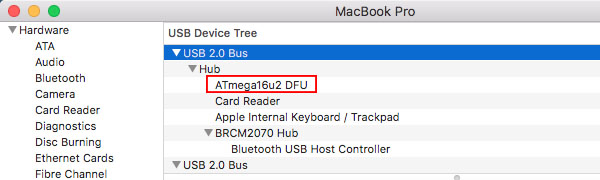
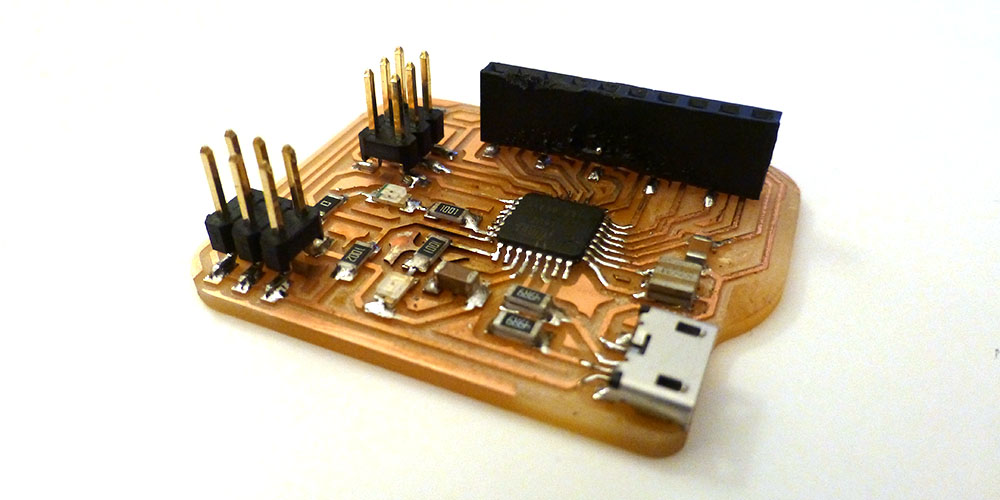
16U2 UPDATE
After tons of debugging help from Tomás Vega, my 16U2 board now communicates with my computer! It turns out my resistors connecting to D+ and D- were too high, so we stacked additional 49.9 Ohm resistors to get the correct resistance (about 25 Ohms, technically they should be 22, but 25 worked). We also found out that the cheapo usb-usb micro cable I was using did not have data transfer capabilities. So I ordered a new data cable, but in the meantime, I had to stick with my Arduino for this week's assignment.
Some important things I learned about debugging:
- Use a multimeter to check all power and ground connections
- Use a multimeter to check the resistance/capacitors are correct
- Use a microscope/really strong magnifying glass to make sure nothing is secretly shorting between your traces. The endmill was dull when I milled, so there were many little copper "flagella" sticking out of my traces.
- Check your schematic.
- If all else looks ok, replace the microcontroller.
- You can stack resistors on top of each other to make a parallel circuit and reduce resistance.
Slogging Through Processing
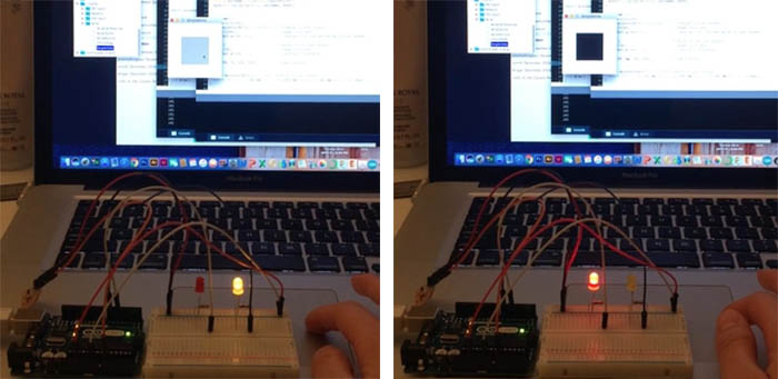
As I mentioned, my dream was to create some kind of javascript application to make a charming web interface for my robot. But that was a huge step from where I was starting (no application programming experience). So I started with some simple exercises in Processing. The first success was writing to the microcontroller to turn on leds. This was just an adaptation of the SimpleWrite example Processing offers.
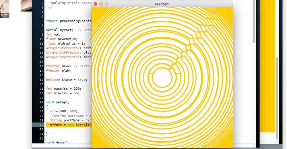
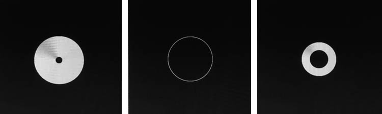
For my second experiment, I wanted Processing to read the microphone values from the microcontroller and visualize the signal as a pulsing circle where the radius was a function of volume. I worked with microphones once before, and I had a really difficult time making something from the signal. So this was an opportunity to overcome that challenge. Reading the value itself was successful, but the visualization was not. In fact, my first attempt resulted in something that would likely cause epilectic seizures.
I identified that the cause of this problem was that the microphone values were changing too much and too rapidly. So I made several attempts to tween the animation between the circles in Processing. The main problem was that Processing does not let you redraw a shape in the middle of the draw() function. If you redraw a shape multiple times within the draw() function, instead of seeing the shape transform, you will have multiple versions of that shape displayed in one frame. I also tried a morph() function, but strange things were happening there, and I quickly abandoned ship.
Instead of trying to smooth the transition between sound values in Processing, a friend recommended I filter the sound data on the Arduino side. This method proved much better. I added a moving maximum filter to remove any sudden drops in the signal, then I smoothed the signal with a moving average filter.
I had a lot of trouble selecting the right datatype for the microcontroller program, but I found that the signal came out best when it was represented as a float. However, I could not send a float over serial to Processing. Instead, I multiplied the float value from the microcontroller program by a factor of 10, converted it to an int, and sent to processing. This fixed the problem.
/*
 *Jackie's billionth attempt at working with microphones
 *Does rudimentary filtering on sound data
 *Sends filtered data to serial
 *processing sketch makes a simple visualization.
*/

//inputs
#define micpin A0

//variables
float sounds[10] = {0,0,0,0,0,0,0,0,0,0};
float filtersounds[10] = {0,0,0,0,0,0,0,0,0,0};
float maxsounds[10] = {0,0,0,0,0,0,0,0,0,0};

void setup() {
  Serial.begin(9600);
  //SET PIN DIRECTIONS
  pinMode(micpin, INPUT);

}

void loop() {
  //Serial.println("we are here");
  float nowsound = abs(analogRead(micpin)-190); //read incoming signal

  sounds[9] = nowsound;

  float soundmax = getMax(sounds);  //get maximum envelope
  maxsounds[9] = soundmax;

  float filtered = getAvg(maxsounds);  //smooth maxsound by moving average
  filtersounds[9] = filtered;


  shiftArray(sounds);
  shiftArray(filtersounds);
  shiftArray(maxsounds);

  int intfilter = filtered*10;//divide when sent to processing.
  //Serial.println(intfilter);

  Serial.write(intfilter); // write the smoothest signal
  //Serial.print(nowsound);
  //Serial.print(",");
  //Serial.print(filtered);
  //Serial.print(",");
  //Serial.println(soundmax);
  //delay(50);

}

//moving maximum filter
float getMax(float nums[10]){
  float themax=nums[0];
  for (int i=1; i<10; i++){
    if (nums[i] > themax){
      themax = nums[i];
    }
  }
  return themax;
}

//moving average filter
float getAvg(float nums[10]){
  float thesum=0;
  for (int i=0; i<10; i++){
    thesum+=nums[i];
  }
  thesum/=20;

  return thesum;
}

//shift values in array back 1 to make room
//for new sensor value
void shiftArray(float nums[10]){
  for (int i = 0; i<9; i++){
    nums[i] = nums[i+1];
  }
  //return nums;
}
I remapped the microphone values (conveniently corresponding to volume) to a range of radii lengths in Processing and finally created a mostly successful visualization. The serial communication did seem a little glitchy and slow, but overall I'm happy with the result. Here's my code and a video of Processing responding to "Soledad y el Mar" by Natalia Lafourcade.
import processing.serial.*;
Serial myPort; //create object from serial class
float val; //sound value from serial.

//Stuff for circles
Circle circle1; // create object from circle class

//mapping
int mapmax = width;
int mapmin = 1;

//sound range for mapping
float soundmin = 0;
float soundmax = 20;

void setup() {
  size(500, 500);
  frameRate(30);
  String portName = "/dev/cu.usbmodemFA141"; // get it from Arduino...
  myPort = new Serial(this, portName, 9600);

  smooth();
  fill(255);
  circle1 = new Circle(width/2, height/2, 1); //start with circle of radius 1
}

void draw() {
  background(51);
  if (myPort.available() > 0){
    val = myPort.read(); // divide back to original size
  }

  print("this is the value: " + val + "\n");

  float mapval = map(val, soundmin, soundmax, mapmin, mapmax);
  circle1.radius = mapval;
  circle1.draw();

}


class Circle {
  float x, y, radius;

  Circle(float x, float y, float radius) {
    this.x = x;
    this.y = y;
    this.radius = radius;
  };

  void draw() {
    background(51);
    strokeWeight(4);
    stroke(255);
    ellipse(x, y, radius, radius);
  }
}
How to Make (Almost) Everything | Fall 2017