Jaclyn Berry
wk13: Networking
Choosing the Right Board
After struggling for several days/weeks with the 16u2, I decided it was time to choose a different microcontroller to work with. There were a few problems with 16u2–one was that I couldn't get DFU working with it after I had programmed via ISP, and the second was that it didn't have a hardware ADC.
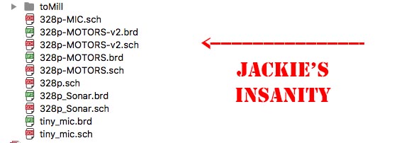
After experimenting with my microphones and motors in previous weeks, I realized that the microphone data might benefit from haivng it's own microcontroller. I struggled a lot trying to figure out how many separate boards I would need. I thought I might need three or four boards total: one for motor control, one for microphones, one for sonar and a master board. But that was insane. So for this week, I separated my microphones to an attiny44 board and will network it with a 328p board.
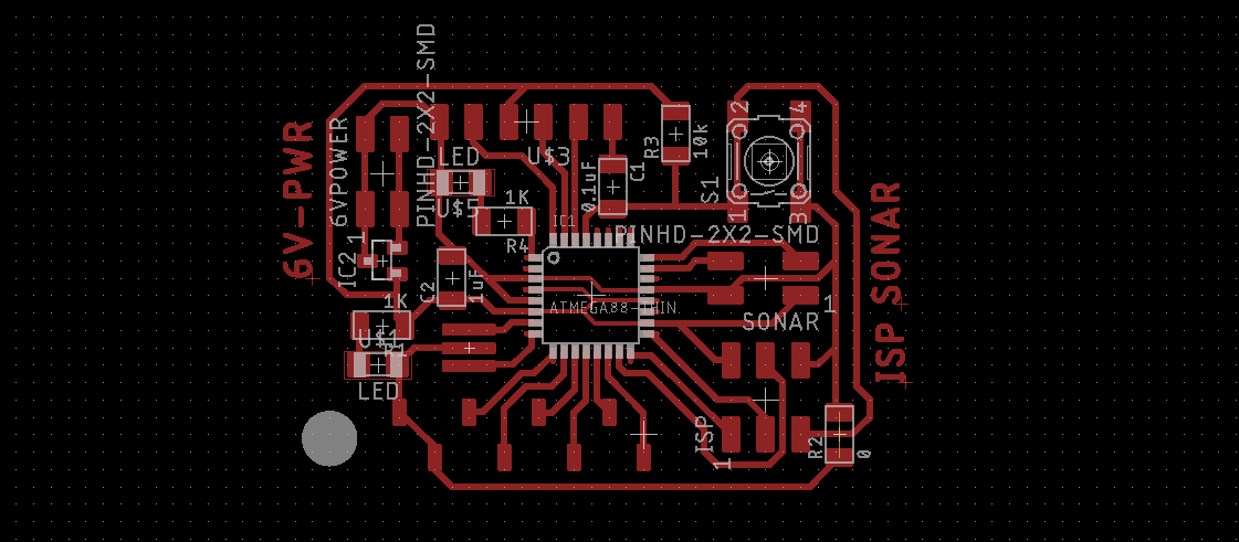
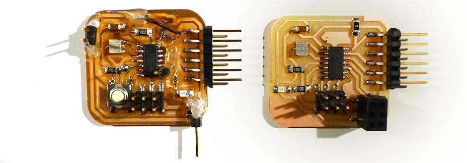
I drafted up a board for the 328p in eagle. It was suprisingly difficult to breakout the I/O pins for a single sided board. I assigned some specific pins for a distance sensor and a several of the ADC I/O pins for the motor and networking connection. I included the FTDI header for serial communication. I attempted to put the motor drivers on the same board, but again, it became really difficult with a single sided board.
My new tiny44 board was a revision of my old tiny44 board from week 5(?). I got rid of the button and assigned several breakout pins for my microphones.

Mill and Stuff
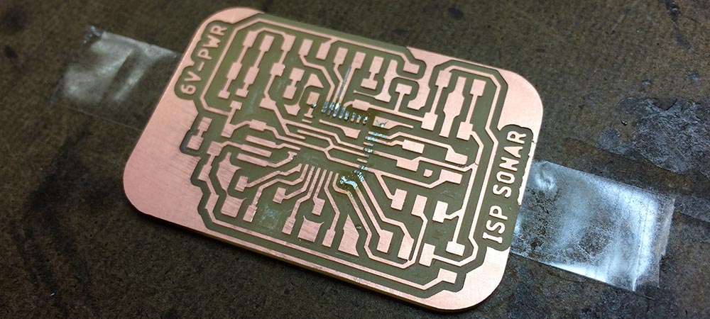
There's only one working pcb mill in the architecture shop these days. So I milled out my boards with SRM-20. I had to trick mods again and tell it that my endmill was 0.012" in diameter for it to get all the pads for the 328p. Even with that, I had to cut a few of the traces with an exacto blade.
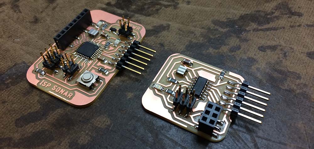
I stuffed the board without too many issues. The first 328p I grabbed had a bent leg so I replaced it. I also accidentally put an led on backwards, but that was an easy fix. I also included a 3.3V regulator that i'm not sure I need, it might need to be replaced.
Networking
For the networking assignment this week, I decided to do a wired connection. My little robot really won't need any wireless communication abilities, and right now my goal is to SIMPLIFY!. After meeting with Amanda last week, I looked in to UART, USART and SPI. Before I decided on how many boards I would need, SPI seemd like a great option–I could have many slave devices with one master and the master could speak/listen to slaves independently. But after two days looking into how I would implement SPI on the attiny, 328p, and possibly the 16U2, it seemed like a very challenging task. Mainly, I couldn't find any SPI libraries for attiny as a slave device and learning embedded C right now is a bit too steep a learning curve. At this point (Tuesday midnight) I was really feeling pressured for time, so I changed plans and started looking into USART communication. With USART, I could just use SoftwareSerial for the attiny and Serial with the 328p and hopefully everything would be fine.
Problems started again when I tried to program the 328p. When I plugged it in, it got burning hot near the power-on LED and voltage regulator. The voltage regulator was intended for when I power my board with batteries, so I think it may have been back-powered or something odd like that. I cut the trace to the regulator and it seemed to fix the heat problem. The next problem was that I couldn't program the 328p in Arduino or with avrdude. In arduino, I got an error about syncing and with avrdude I got the rc=-1 error. Will helped me debug my board, but we couldn't figure out the problem. So, I will have to scrap this rev, and try a new one.
In the meantime, I still needed to network two of my boards. I had my old 16u2 board handy, but I had never set up USART for it. I looked throught the datasheet and found example code for setting up USART. I literally copy pasted the code into a C file, made a really simple program and tried to generate a hex file with avr-gcc. But avr-gcc didn't recognize the registers! What?! I checked with Tomás and another friend, and they thought I might need to use the header file. Now Tuesday 2AM, I was really panicked.
Frankenboard Lives!
Revising my plan again, I decided to try and network my old attiny44 board with my new attiny44 board to simply toggle leds. I think I was panicking too much at this point because I was having trouble loading blink sketches correctly to the board. Will helped me a lot with this process and pointed out that Arduino-land has different pin assignments for the attiny. As it turns out PB2 is just pin 8. So we got the leds blinking, step one accomplished!
Step two was getting the boards communicating with softwareSerial. I set up the new attiny44 board to turn and LED on and off when it reads "H" or "L". We uploaded this and tested it in the serial monitor. Success!
#include
#define Tx A1
#define Rx A0
#define ledpin 8

char instruct ='H';

SoftwareSerial mySerial(Rx,Tx);


// the setup function runs once when you press reset or power the board
void setup() {
  pinMode(ledpin, OUTPUT);
  pinMode(Tx, OUTPUT);
  pinMode(Rx, INPUT);
  mySerial.begin(9600);
}

void loop() {
  // put your main code here, to run repeatedly:

  if (instruct == 'H')
  {
        mySerial.write(instruct);
        instruct ='L';
  }
  else if (instruct == 'L')
  {
    mySerial.write(instruct);
    instruct = 'H';
  }
  delay(500);
}
Step three was getting the Frankenstein attiny to write instructions through serial. I wrote a program to have Frankenstein attiny44 write "H" and "L". We checked the serial monitor, and it worked!
#include
#define Tx A1
#define Rx A0
#define ledpin 2

SoftwareSerial mySerial(Rx,Tx);


// the setup function runs once when you press reset or power the board
void setup() {
  // initialize digital pin LED_BUILTIN as an output.
  pinMode(ledpin, OUTPUT);
  pinMode(Tx, OUTPUT);
  pinMode(Rx, INPUT);
  mySerial.begin(9600);
}

// the loop function runs over and over again forever
void loop() {
  if (mySerial.available())
  {
    char offon = mySerial.read();
    if (offon=='H')
    {
      digitalWrite(ledpin,1);
    }
    else if (offon=='L')
    {
      digitalWrite(ledpin,0);
    }
  }
}
Finally I hooked the two boards together. I powered them using the FTDI VCC/GND lines connect on a breadboard, then crossed Tx and Rx lines between the boards. And the new attiny44 started blinking! What a victory!
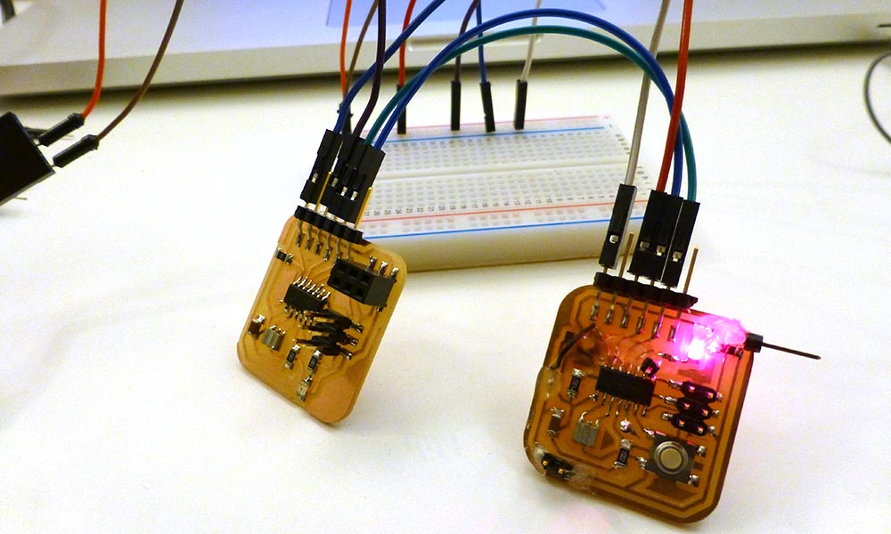
I still need to successfully make a 328p board that can use serial from arduino. But at least now I know how to network boards. Hopefully the next revision will be less painful. Special thanks to Will for helping me debug this week!
How to Make (Almost) Everything | Fall 2017