Jaclyn Berry
w3: Electronics Production
Milling and Programming the Programmer
This week our assignment was to fabricate a programmer for an ATtiny. This was my first time milling a circuit board and a great opportunity to practice soldering. I used Brian's FabTinyISP.
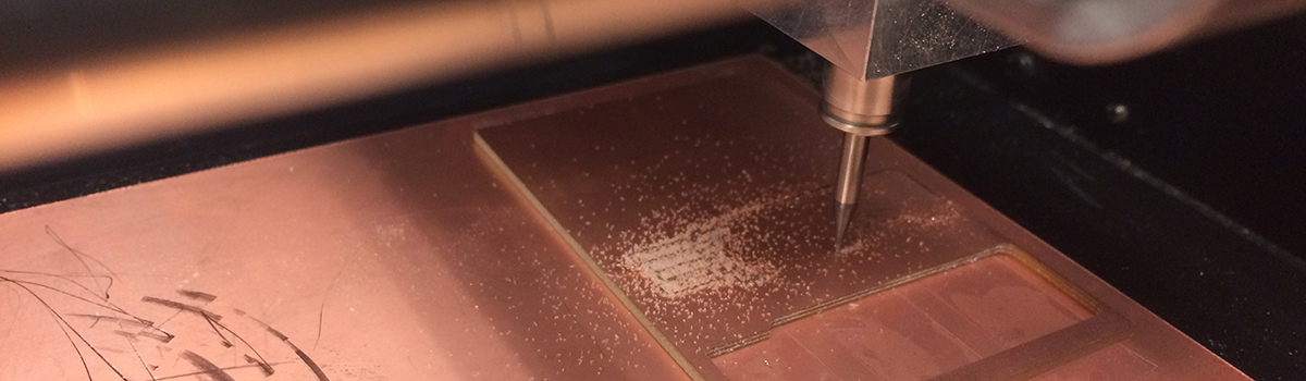
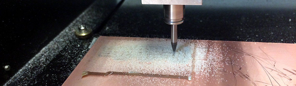
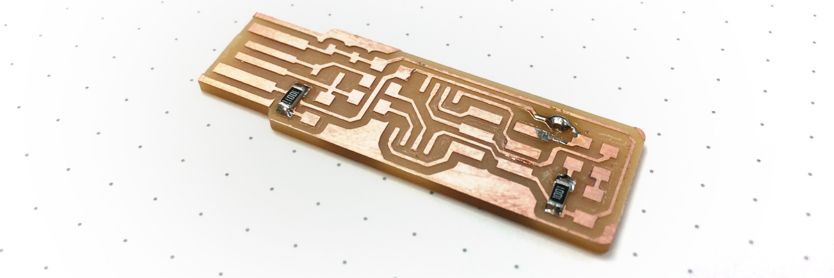
It took me a few tries to get nice results with the endmill. On the first attempt, the endmill did not cut all the way through the copper. On the second attempt, I readjustd the endmill z-height by applying a slight downwards pressure into the copper. This adjustment worked much better, but there were a few spots where the traces came out slightly jagged.
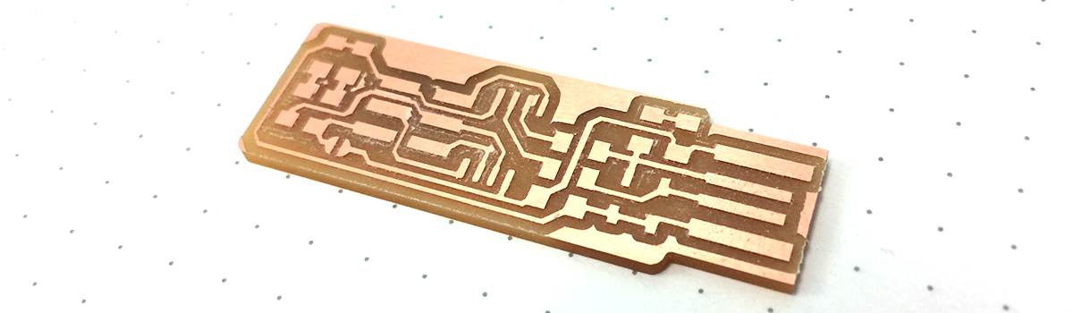
I wanted to get really clean traces so I inspected my set-up once more. The endmill itself looked in pretty good shape, so I guessed that one side of the bed was slightly warped. I set up the FR1 on the opposite side of the platform. The traces came out much cleaner with only a few easy-to-remove stray pieces of copper.
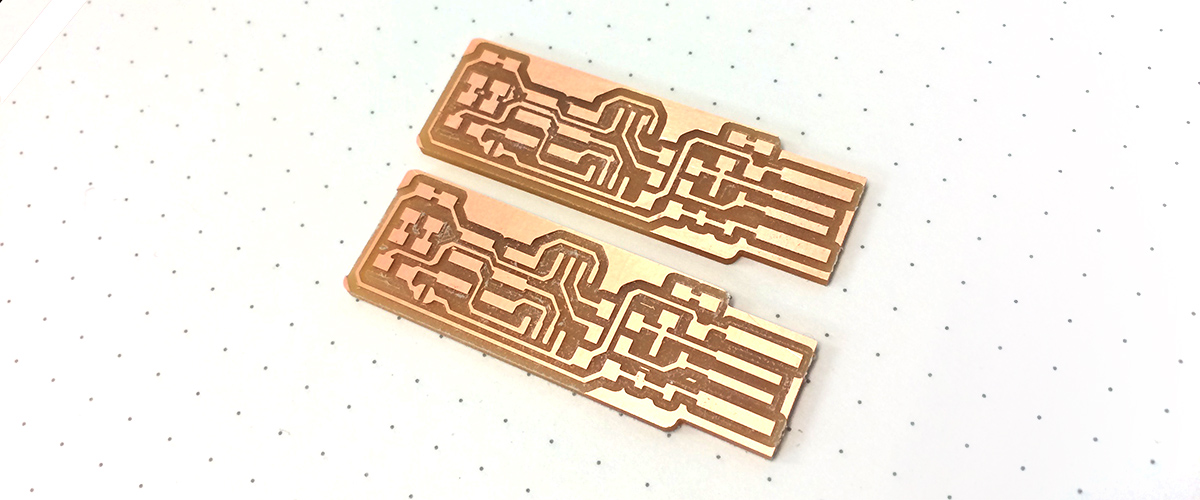
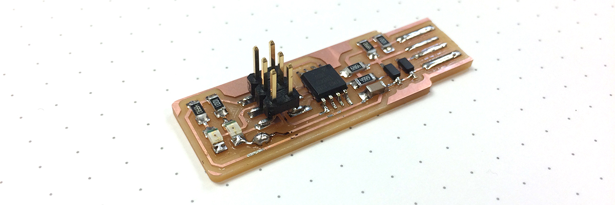
I washed the PCB and trimmed the extra segment of copper at the usb connector. I had not soldered in a while, so I practiced soldering a few resistors on my uglier board. Once I felt comfortable, I started soldering the real thing.
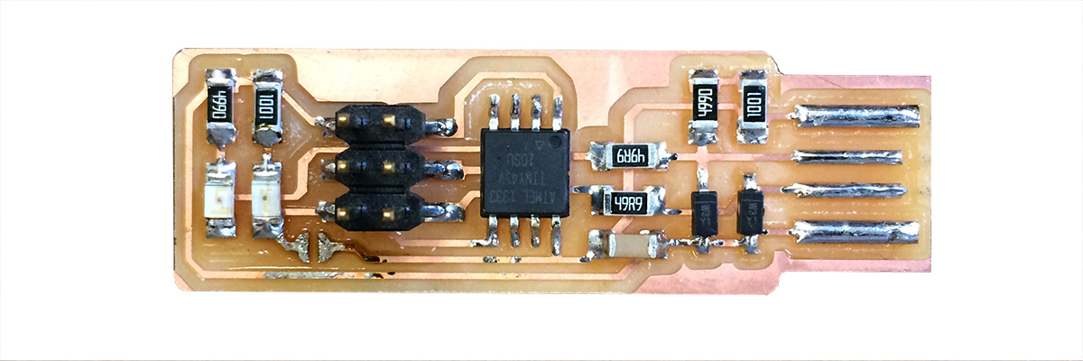
I soldered from the center (the ATtiny45) outward. I ran into a little confusion with the diodes. First I was confused why the cathodes on the Zener diodes were not connected to ground. Jonah explained that Zener diodes allow current to flow in both directions. I will have to read about this component to understand more. Second, I tried to test the color and polarity of the LEDs with the small multimeter in the fabshop. As it turns out, these multimeters are a bit too affordable to help determine LED polarity. Fortunately, these LEDs had a green line to identify the cathodes (thanks Justin and Jonah).
Once soldering was finished, I moved on to programming my tiny. I attached a strip of thick paper to the back of my programmer to make a better usb connection. I worked with one of my classmates, but we ran in to a few problems. First, we had trouble identifying pin one on the ISP header. There was rectangular nib on the side of the header as well as a black dot on the bottom of the header. Of course, these two indicators pointed to different pin one orientations. We found out later that the rectangular nib identified the orientation. Second, we had some problems running "make flash." Running this command as administrator (sudo) solved this problem.
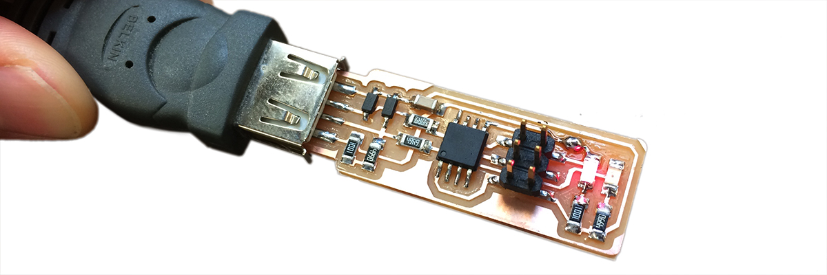
After programming, I removed the blob of solder connecting Vcc from Vprog.
How to Make (Almost) Anything | Fall 2017