Jaclyn Berry
wk9: Output Devices
Drivers and Things...
This week I attended my first conference ever! An interesting experience, but it left me limited time to figure out things for this class. There were two output devices I needed to explore: first, motor drivers for my antisocial robot, and second, nitinol wire as a system for actuating fabric.
Motor Driver: Eagle
I considered creating a new microcontroller board with the H-Bridge DC Motor drivers, but I decided it was more efficient to create a motor driver breakout board for this week's assignment. I intend to use tank-drive steering for my antisocial robot, so I included two H-Bridge Motor drivers on my board and a bunch of header pins to connect to a microcontroller.
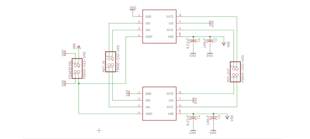
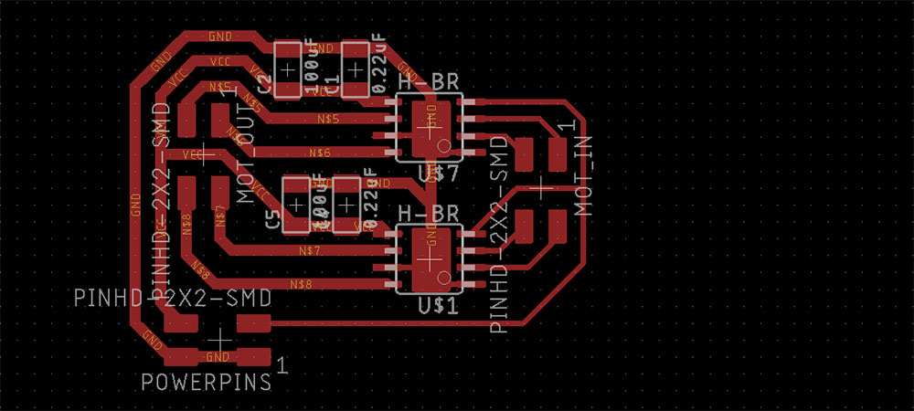
It took me a few tries to get the board right. I had a lot of trouble deciding what type of header pins to use and I got a little bit confused with the LSS pin. At one point I had to undo around 50 steps to get an old design back. The high voltage power source and ground lines required a thick ground trace and the drivers required a ground polygon to dissipate heat. The final design turned out pretty nice though. My thick traces were 0.032 in and my thin traces were 0.016 in.
Motor Driver: Stuff
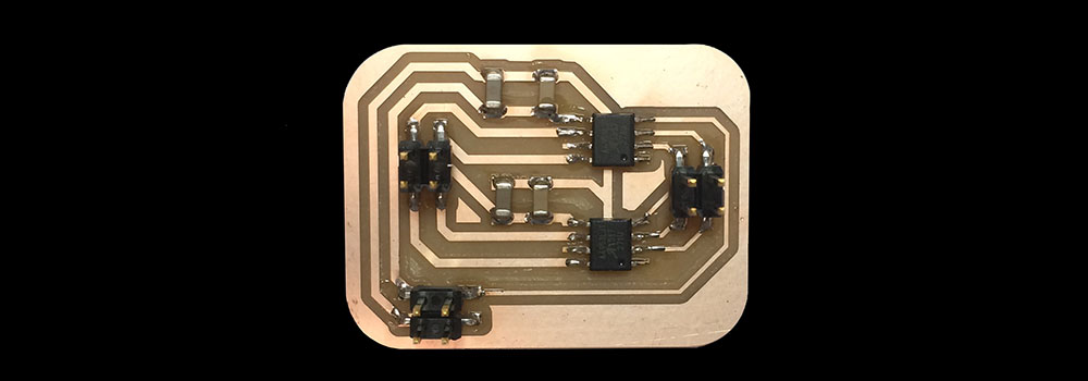
I milled the board out on the SRM-20 then soldered all the parts on. These steps went really smoothly (special thanks to Jonah and Paloma for bringing extra copper sheets to the shop). I'm considering putting some hot glue around the header pins just to make sure the traces do not lift up and break from wear and tear.
Motor Driver: Test
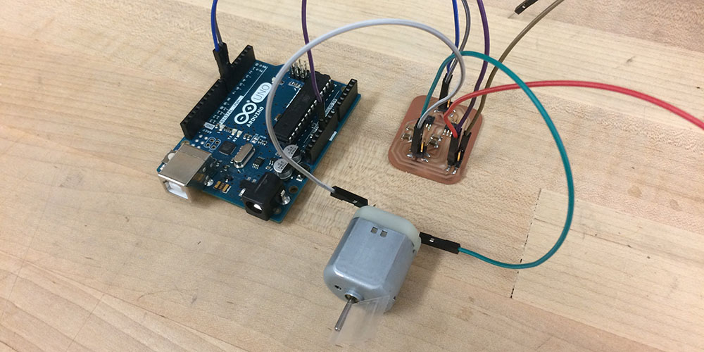
My old Attiny44 board from previous weeks did not have any breakout pins for me to connect to, so for the sake of efficiency, I opted to connect my motor driver board to an Arduino UNO. I wrote a really simple program in Arduino just to test my driver and make sure it could drive my motor in both directions. I hope to do this in C if I have time later today or tomorrow.
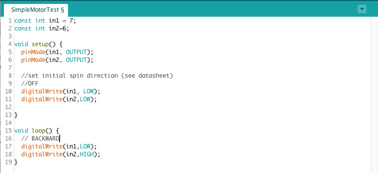
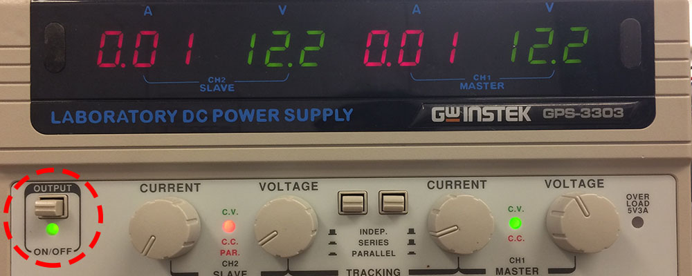
I connected the motor driver to the Arduino and a 12V power source in the architecture shop. It took me a few tries to figure out why the power supply was not supplying any power, then I realized there was a button for "OUPUT."
And it worked! In both directions! It looks like a regular DC motor will be way too fast for my little robot, so I will have to invest in some compact gearbox motors. I considered trying to make my own gears, but I don't think I will have enough time to do that for this project. Maybe another time...
MOSFET: Eagle
Up next was figuring out how to use MOSFETs as a switch for high current loads. In another class, I am trying to use shape memory wire to actuate a sleeve. Currently we are using a relay to pulse the shape memory wire, but the sound that the relay makes while switching is not going to work for our experiment. So... MOSFETS!
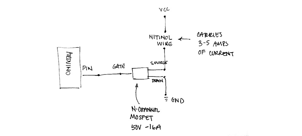
I started by sketching out how I thought the MOSFET should be hooked up to a microcontroller and nitinol wire. I have used transistors before, and it turns out they are very similar. I drew up a test board with a single MOSFET. I wasn't really sure if it would work the way I intended. So it was time to try it out...
MOSFET: Stuff
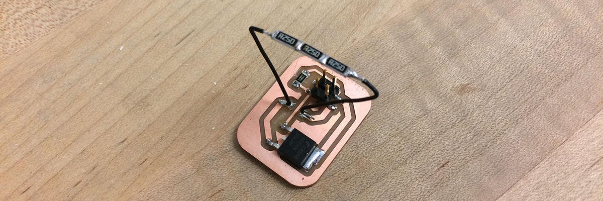
I milled the board on the SRM-20 and soldered all the parts. For no apparent reason, I decided to put a 10K resistor where my nitinol would eventually connect. This was totally random and I ended up removing it later.

When I tested the nitinol wire before, I connected it directly to a power source at less than 2V with approximately 4A of current. The challenge is replicating that on the tiny board. Neil recommended I test the circuit (current, voltage, resistance, etc.) with a multimeter before I attach the wire so I would not fry the nitinol wire.
I tried calculating what resistance I would need before the nitinol wire to attain the correct current. I used V = I * R where the voltage is 3 volts (controlled by a voltage regulator) and I is 4 Amps. this left me with R = 0.75 Ohm. I soldered three 0.25 Ohm resistors together in series and attached them to my board.
I found out later that this was not a good solution for a high current load... But before that, I tried to confirm that my resistance across the resistors was indeed 0.75 Ohm. The weird thing was that the "affordable" multimeters in the architecture shop all read 0 Ohm. I've learned not to trust these multimeters, so I decided to just go with what I had.
MOSFET: Test
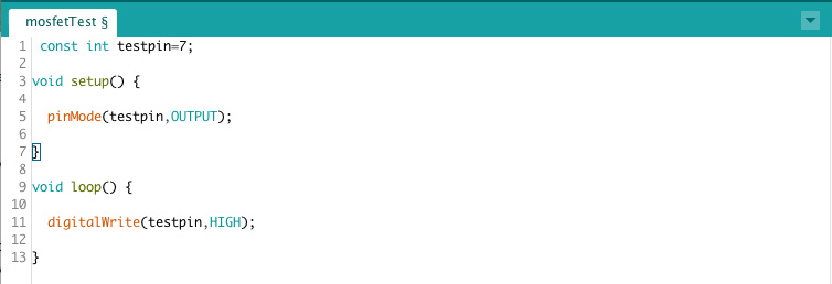
Again, I hooked up my board to my Arduino UNO and uploaded a very simple program just turning the MOSFET gate HIGH.
I tried attached the power supply but the current would not go past 0.2 Amps. I found out that you have to set the maximum amperage before you set the power supply to "OUPUT." This power supply would not go past 3.2 Amps. Anyway, I set the power supply to 3V with maximum 3.2 amp.
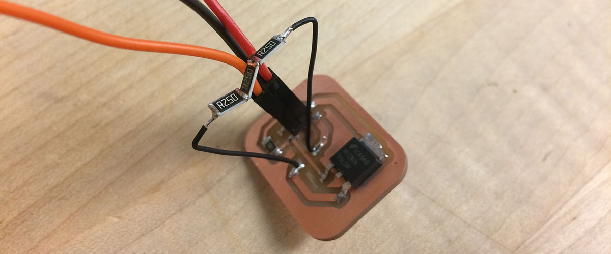
It turned out very poorly. I'm not sure if the gate stayed open after I programmed the Arduino, but some strange things definitely occurred. I attached the power supply power and ground to the MOSFET board, but the arduino was not powered. The resistors I soldered together immediately started smoking, so the circuit was shorting through the MOSFET (I think). I'm not really sure what to do next, but I better figure out quick because I need this part THIS WEEK!
TUESDAY NIGHT MOSFET UPDATE!
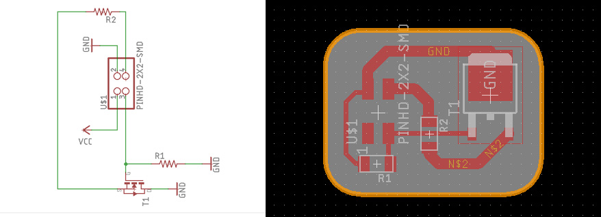
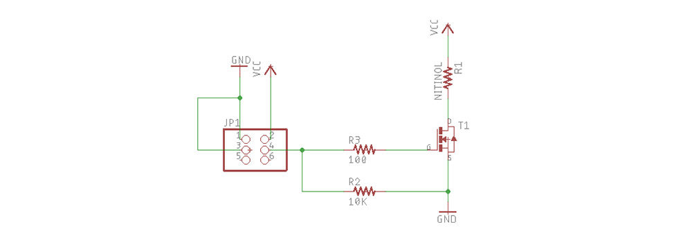
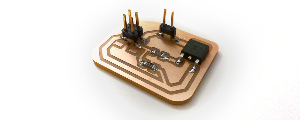
I revisited the datasheet for the N-Channel MOSFET I was using. It turns out I missed several things in my circuit... I needed to place a 100 Ohm resistor between the Arduino pin and the gate because the gate has a maximum voltage rating of 2V. More importantly, my power and ground were connected incorrectly to the source and drain. This was a pretty drastic change, so I drew a new board in eagle.
I milled and stuffed the board. The SRM-20 had a few weird errors, but I got it to work normally in the end. The shop ran out of 2x2 header pins, so I got a little bit creative and broke a 2x3 pin into a 2x2 and 1x2 pin. The 1x2 header was for an easier connection to the shape memory wire.
And it was time for the moment of truth. I hoooked up the new MOSFET board to my Arduino, the shop power supply, and my shape memory wire. I uploaded a simple sketch to actuate the shape memory wire (6 seconds on, 3 seconds off).
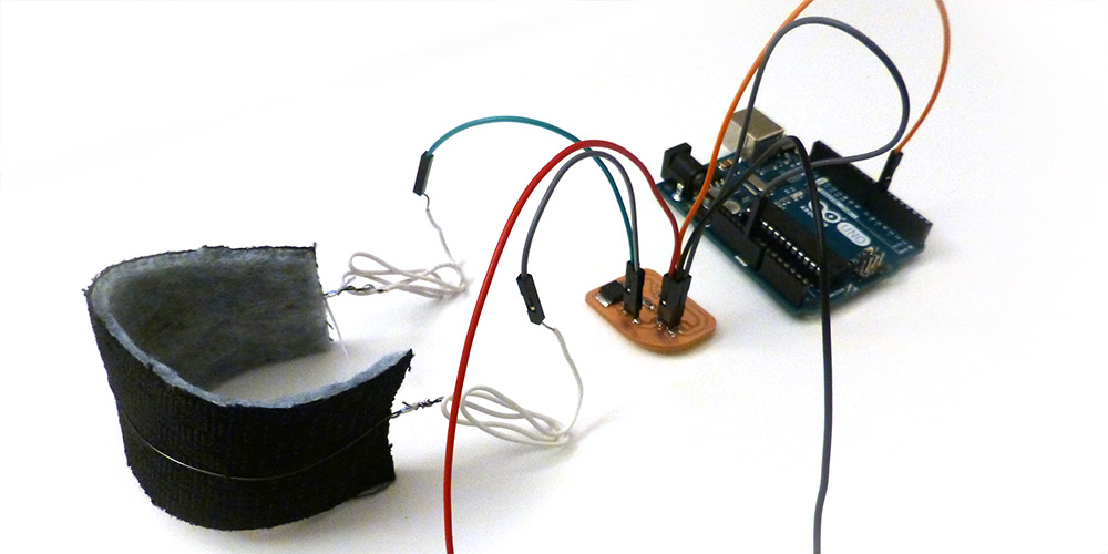
And it worked! A really good way to end a very long day. Here's a short video at ~2x speed:
How to Make (Almost) Everything | Fall 2017