"The road to hell is paved with good intentions."
I used to thought that this meant that people who do terrible things typically meant to do good, but now I realize a new meaning: overly ambitious makers with good intentions will find themselves in hell the night before the project is due when suddenly NOTHING WORKS.
My name is Kate Weishaar, and this is my journey.
Phase 1: The Naive Dreams
Original plan:
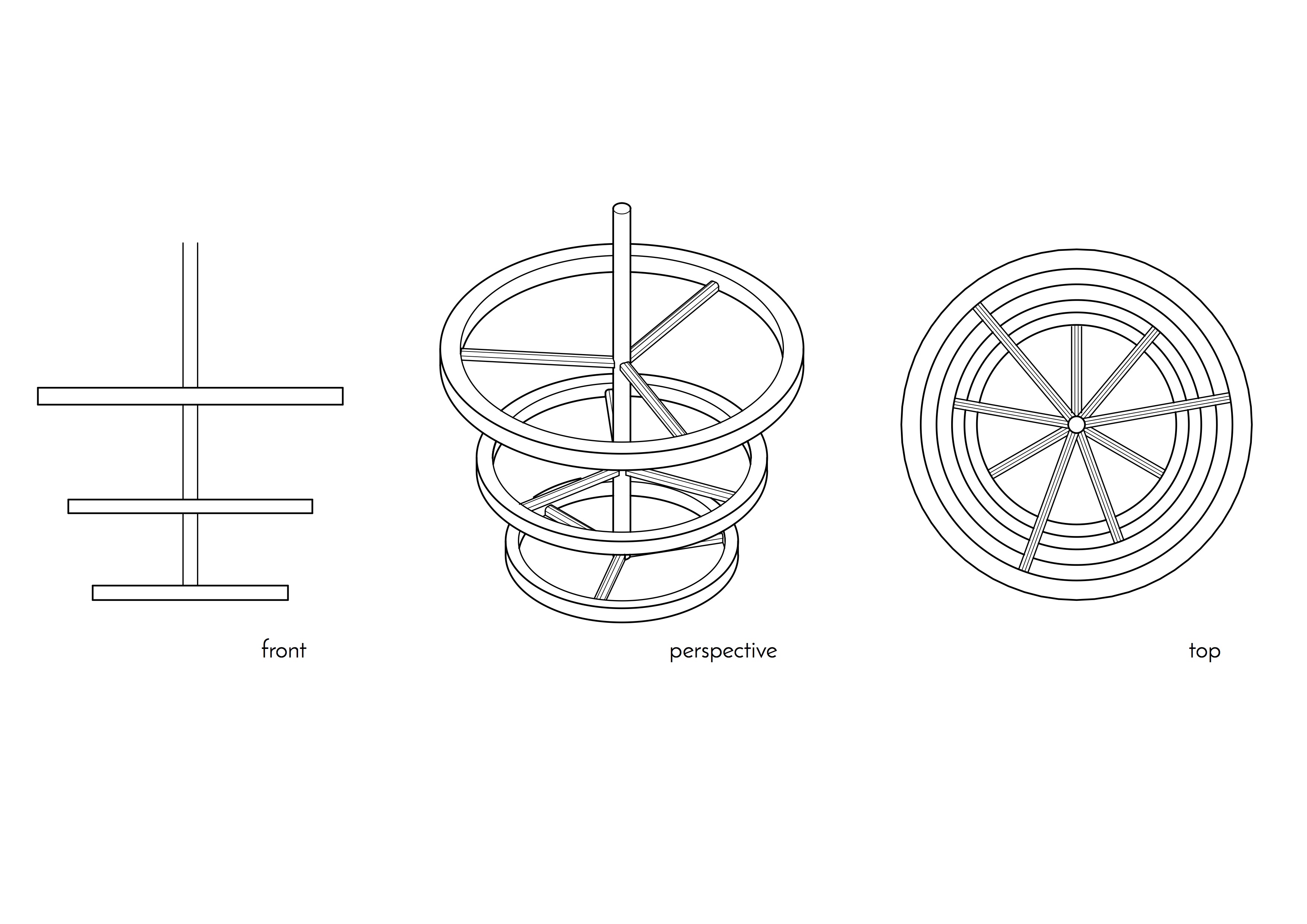
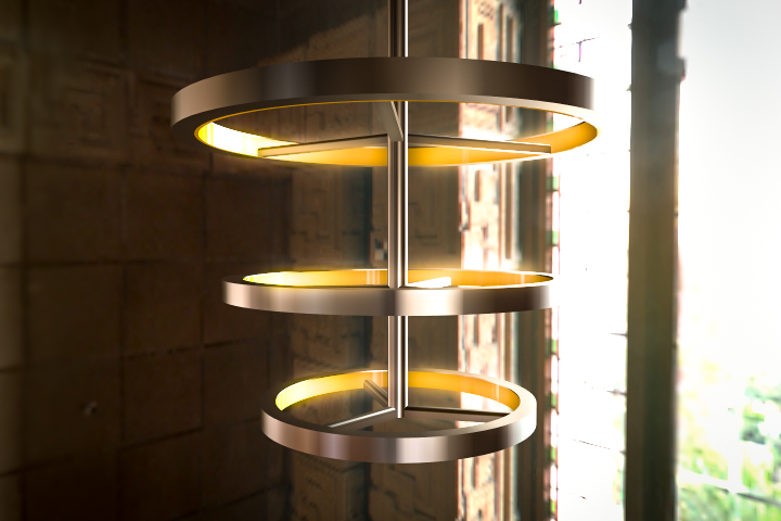
For my final project, I want to build a chandelier that changes to respond to the user's mood. The quality of light in a room can have a pronounced effect on a user's mood and behavior, depending on factors like brightness, how warm or cool the color is, and whether the light flickers or is constant.
I intend to play with these factors and create a wearable control mechanism in the form of a bracelet or ring that the user can interact with to determine what qualities the light will have. The wearable will have a sensor measuring biological signals like body temperature or heart rate that correlate to mood. It will transmit these signals via IR to the chandelier, which will be programmed to respond with a certain frequency of light.
I will use the output devices week to work out the LED components of the chandelier and get them to respond to sample input data. I will then use the input devices week to figure out how to set up the sensors in the wearable part, and I will use the networking and communications week to connect the two. I will build the physical structure of the chandelier and the wearable using a combination of CNC machining, molding and casting, and 3D printing once I know more about the affordances and constraints of those processes and the corresponding materials.
Revised plan:
In the interest of not pushing my patience with electronics any further than necessary, I decided to scrap the wearable to give myself more time to design the chandelier and fewer points of failure when it comes time to debug. Instead of picking up on the user's mood via a wearable, I will build a small remote control with buttons that indicate different possible moods. This will be much easier to control and will allow me to have preset values that do not need to be calibrated for each wearer. The remote control will have buttons for studying, normal social activities and hanging out, and calming down before bed or when overly stressed. I can still use IR to connect the remote with the chandelier.
I bought some excellent and reasonably cheap cool/neutral/warm white LED bulbs from Home Depot, which I plan to test during output devices week. They work by cycling through the three modes (off->cool->off->neutral, etc.) with a normal switch. I want to hack this switch mechanism so it can be done by the remote control. If I really step up my programming game, I may also find a way to bypass the off and go directly to the desired output, but we'll see.
Update: After breaking the top off of one of the bulbs, I discovered how the bulbs actually work and decided it would probably be easier to make my own (though not necessarily in bulb form). The three color modes were just dictated by three separate sets of tiny LEDs, so that each set only produced a single shade of white. The cool and neutral had more LEDs than the warm, as they were intended to be brighter.
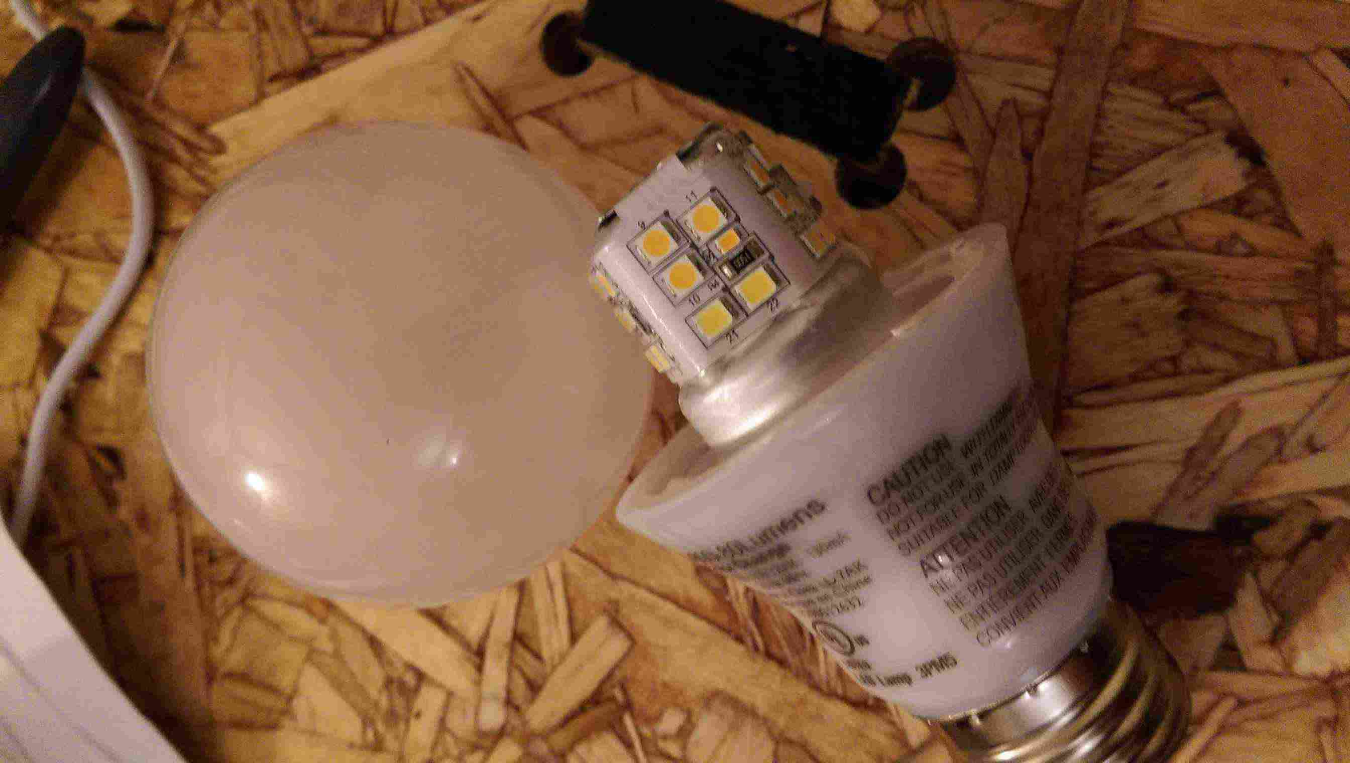
At this point, I'm confident enough in my soldering skills that I could easily build a line or array of LEDs in whatever shape I want, leaving me less constrained form-wise for my chandelier. Creating my own array would also allow me to use PWM to fade between the three sets and achieve a full spectrum of white colors instead of three discrete modes. My next steps will be to design the chandelier itself so I can determine how many LEDs I will need and to design and build a controller that uses a potentiometer to vary the output.
Revised revised plan:
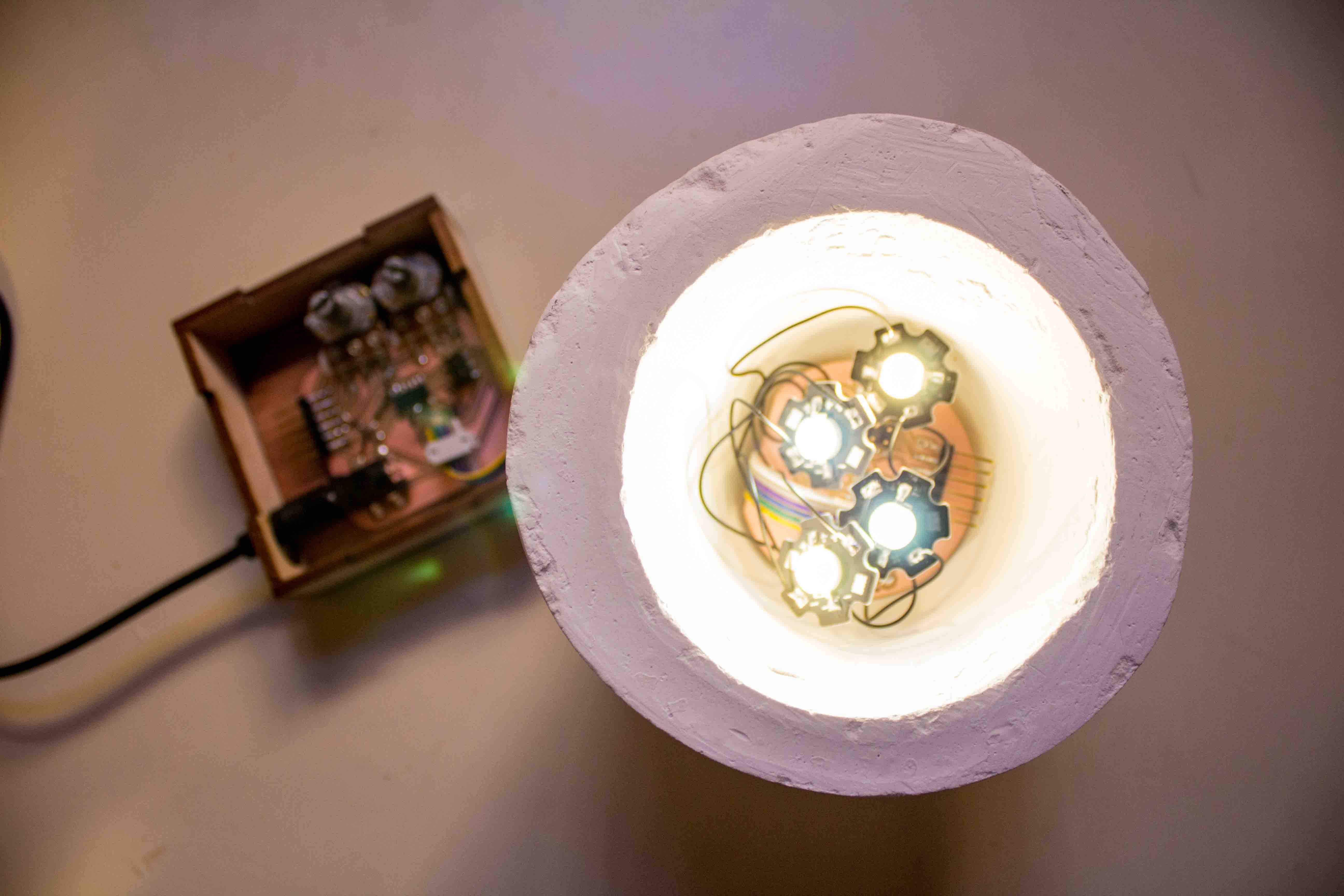
There comes a point in every undergrad's life when she realizes that she is in no position to own a chandelier. Okay maybe that's just me. Anyhow, I decided to make a more tiny-apartment-friendly design: a set of lamps that can be arranged around a room and controlled by a single controller. Each lamp will contain a very bright cool white LED and a very bright warm white LED as well as a controller board that can detect signals from the remote and dim each LED accordingly.
Phase 2: Making it Happen
Once I decided to make a series of networked lamps, I began to figure out what specifically I would need to make. The communication via IR remote would be my main challenge, but I would also need to find appropriately powerful LEDs, determine the necessary resistors and power supply to power the LEDs, design a controller with buttons or a potentiometer to allow for user input, and design the packaging for the controller and the lamps themselves.
I first tried to find LEDs, knowing that the small size of the lamp would constrain my possibilities. I didn't want to use an LED strip because it would not look particularly clean with the geometry, but I also did not want to solder a ton of tiny surface mount LEDs. I ended up finding and ordering packs of warm white and cool white 3W LEDs from Sparkfun.
I then tried to figure out the IR communication. At the time, I did not know the difference between an IR receiver and an IR detector, so I thought the IR detectors in the shop would do the trick. After attempting to build my remote control during networking and communications week, I realized that the IR detector would only detect the whether IR was present, not the specific codes I wanted to send. I then tried to find IR receivers and ended up ordering some on Amazon that I hoped would work ("hoped" here meaning "felt fairly confident about based on reading the datasheet and running it past Calvin", of course).
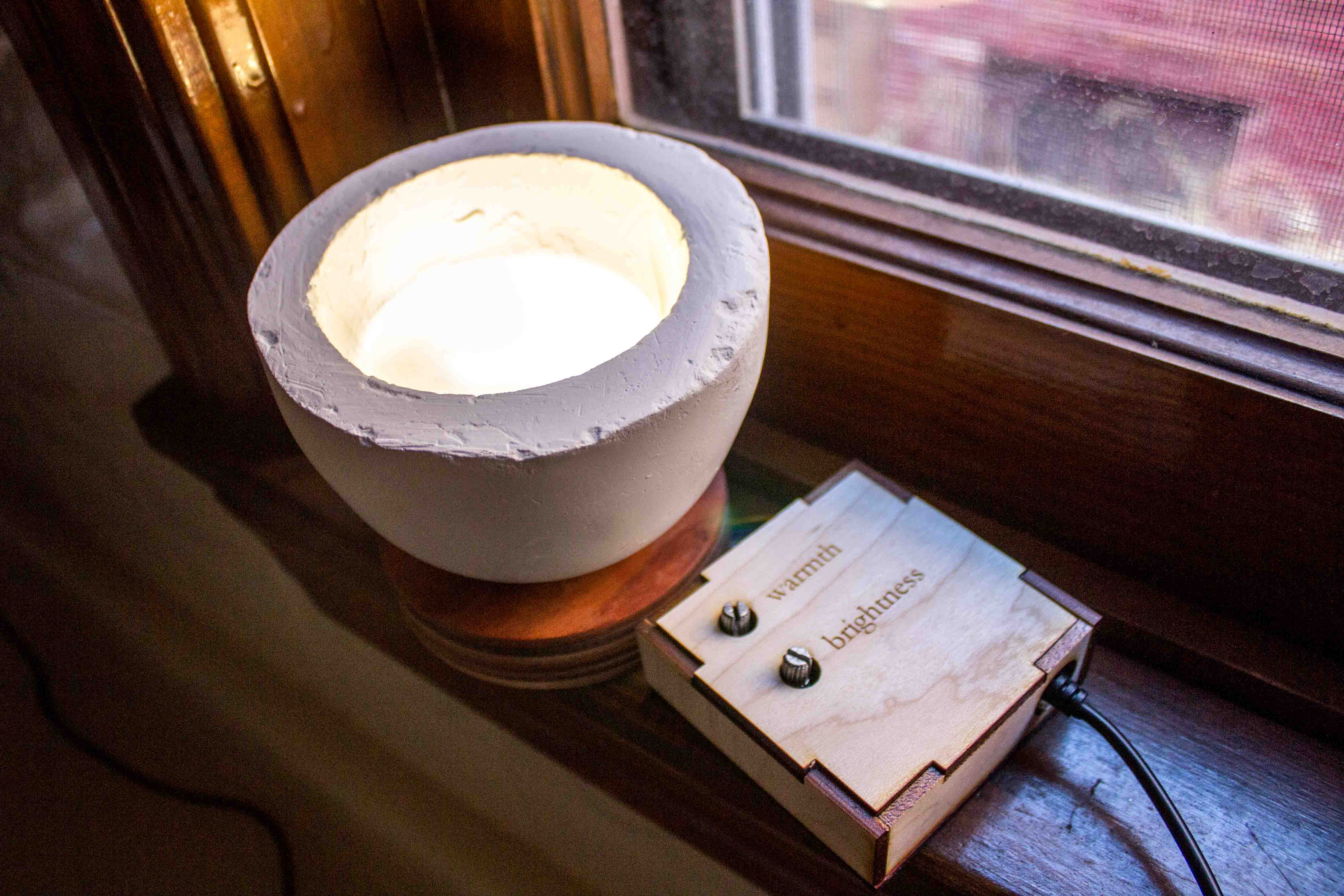
I then went about designing the various parts of the system: the lamp base, the two boards, and the housing for the remote. The lamp base I wanted to be fairly small and use a mixture of warm wood and white to match my bedroom. My initial thought was to 3-axis mill the wood and cast drystone for the white portion. For the shape, I was inspired by a cup of tea because it too is small and cozy and can brighten moods. I wood create a drystone cup to hold the lights and a wood saucer for the cup to rest in. In the interest of both saving time and creating a super smooth surface finish, I decided to use plastic bottles to create the mold.
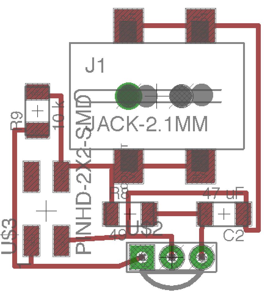
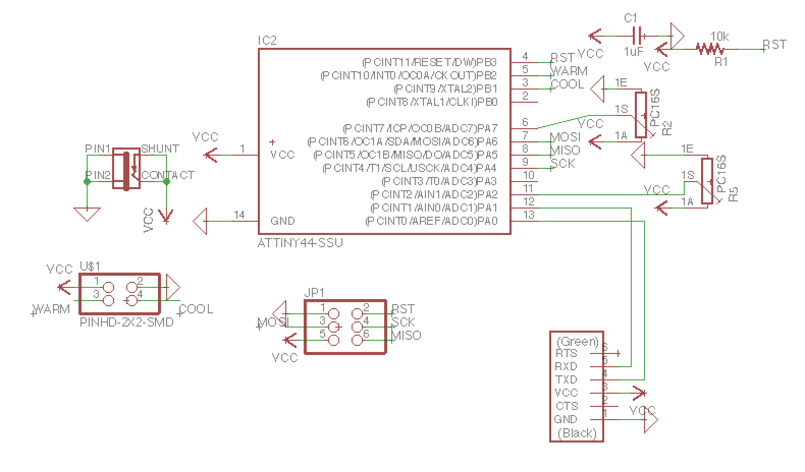
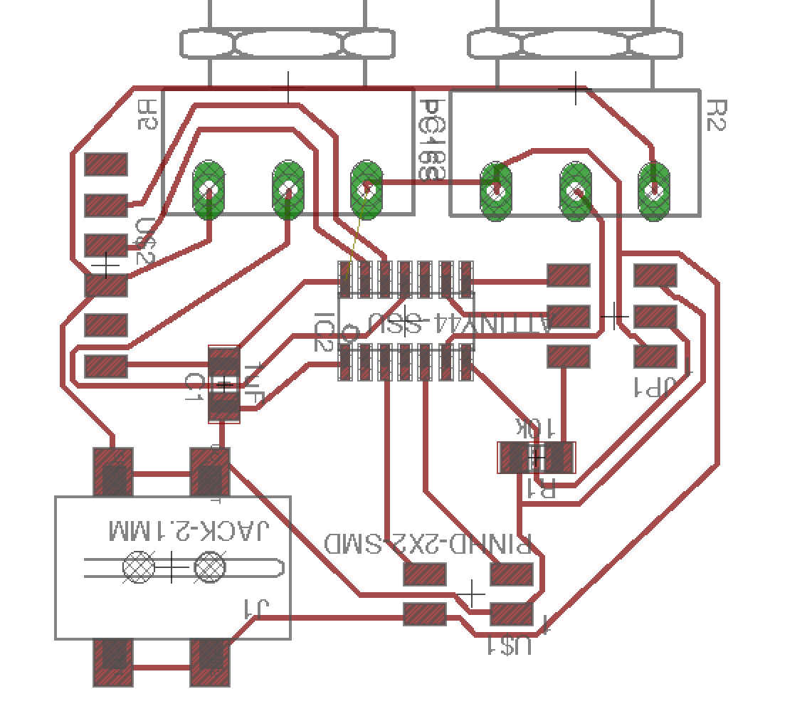
I designed the boards to fit into the physical constraints of the system. The light board would have an external receiver board that could read IR signals without be blocked by a wall of drystone, while the light board itself would rest inside the cup. After calculating the current demands of the LEDs I had chosen, I decided that using a 5V AC to DC wall adapter would work much better than batteries, which I would have to change far too often to be practical as a lamp. For the sake of convenience, I put the jack for the power adapter on the external board with the IR receiver. I then added a header to connect the IR receiver board to the light board via a hole in the bottom of the lamp.
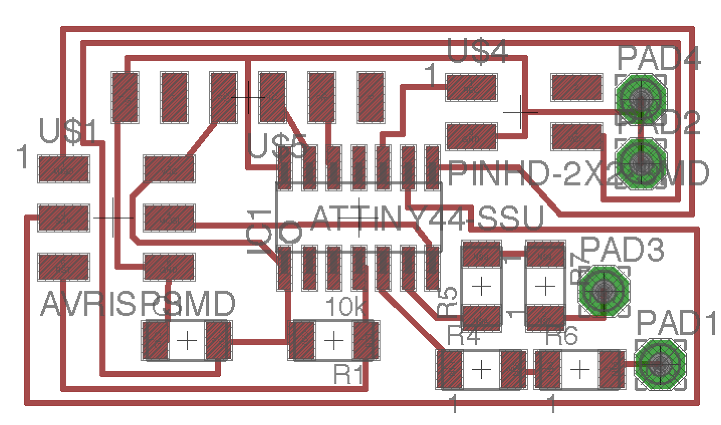
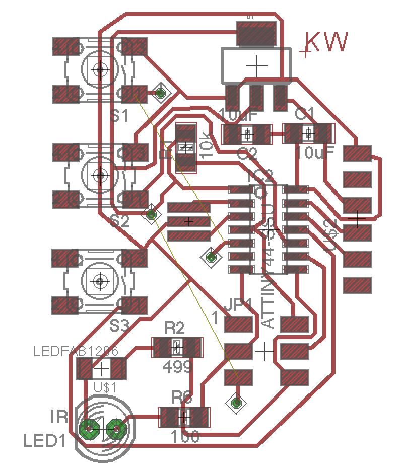
For the remote control, I decided to use three buttons: one to make the light color warmer, one to make it cooler, and one to turn it on and off. I stacked the buttons in a line and positioned the IR led so that it would stick out the top for easy aiming, then designed the rest of the board around those spatial constraints.
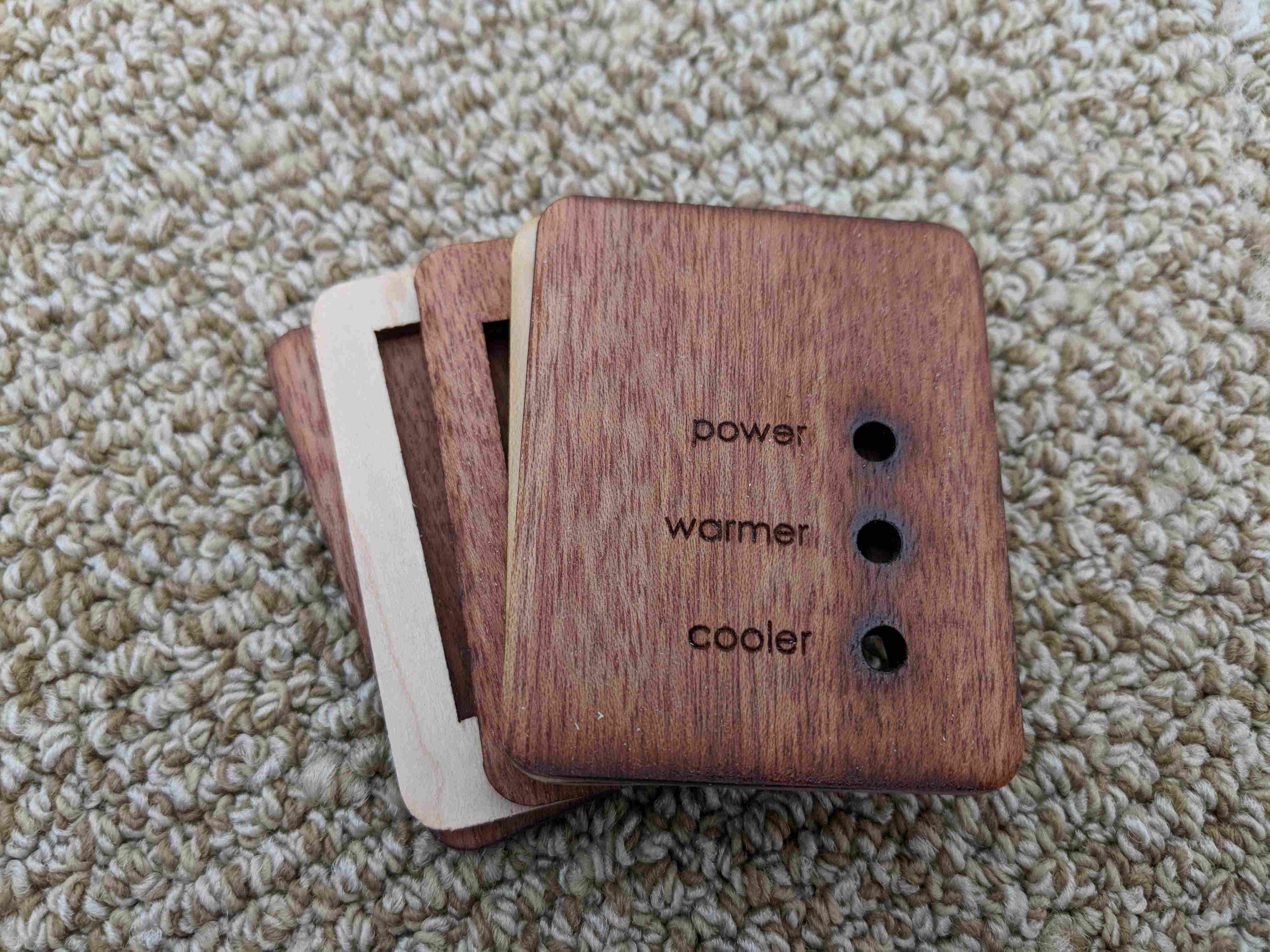
I also designed the housing for the remote based on the positions of the buttons. I wanted to keep it fairly small, so I planned to remove the headers after programming because they were no longer useful and could be re-soldered fairly easily if needed. The shape was constrained by the position of the IR led, the buttons, and a small battery holder that I had purchased on Sparkfun. 3D printing seemed like the obvious choice because remote controllers are typically plastic, but I wanted something more elegant and visually connected to the lamp itself, so I decided to laser cut the controller housing out of wood and glue it together to make the frame. I also intented to screw the bottom piece onto the remaining stack so that it could be unscrewed when the batteries needed to be changed, but the wood split when I tried to drill into it, and I didn't have time to order smaller screws. I was still quite happy with the wood housing, and I made a gap in the bottom large enough to slide out the battery holder as needed.
Phase 3: How to Break (Almost) Everything
It was in the final push to actually build and program everything that things started going horribly awry. First of all, I ended up moving the weekend before the deadline (awesome timing, right?), which significantly cut down on my work time and resulted in things going mysteriously missing throughout the packing process. Second of all, I realized that no one I know drinks soda, so I ended up having to buy a 2-liter bottle of crappy iced tea just to be able to make a single mold.
When I finally got around to casting, I cut up a 2-liter bottle and a 1-liter bottle and hot glued them to create the mold. I hacked together a stand with scrap foam to hold up the bottle while I poured the drystone, and then I got ready to cast the cup.
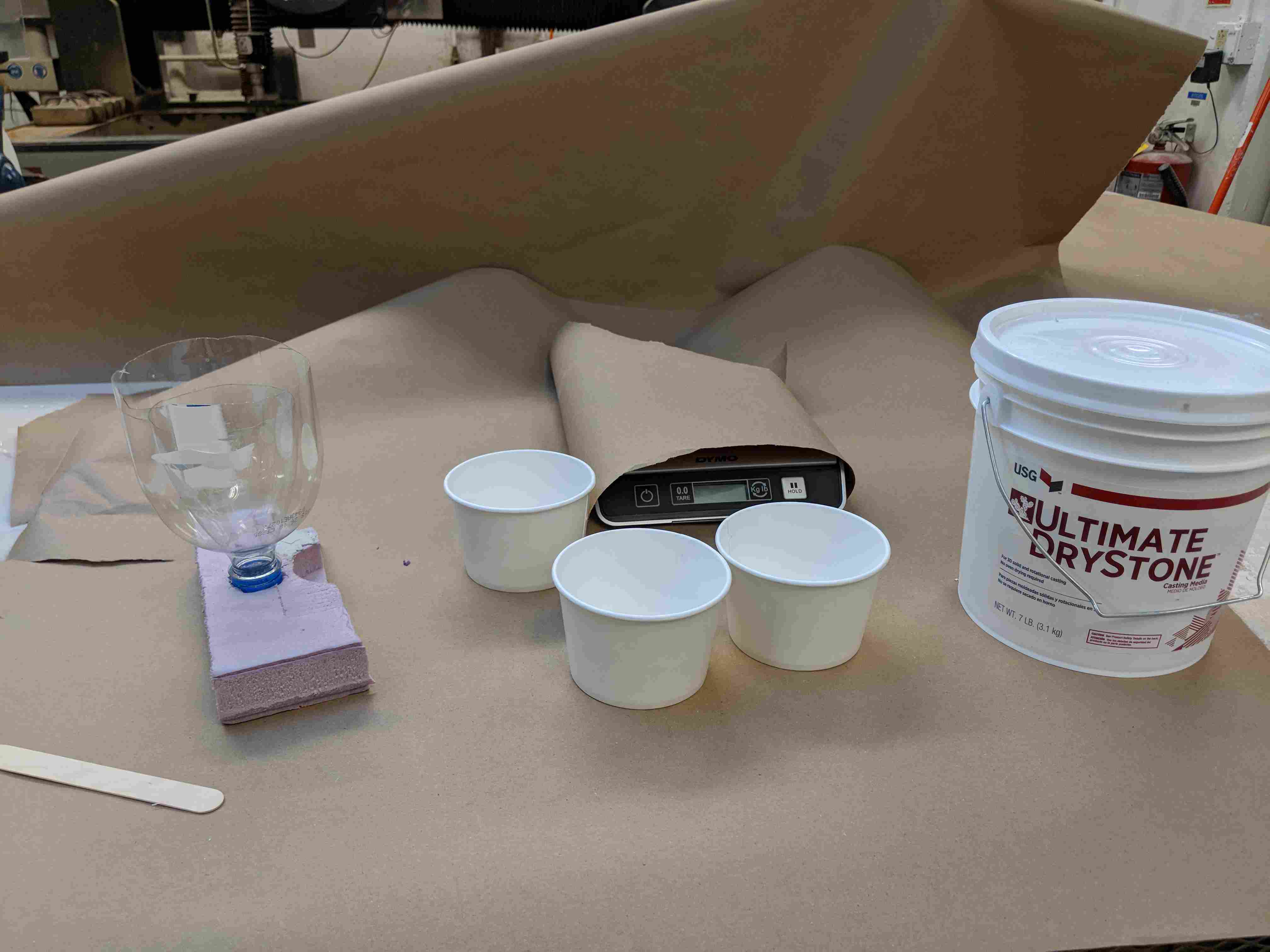
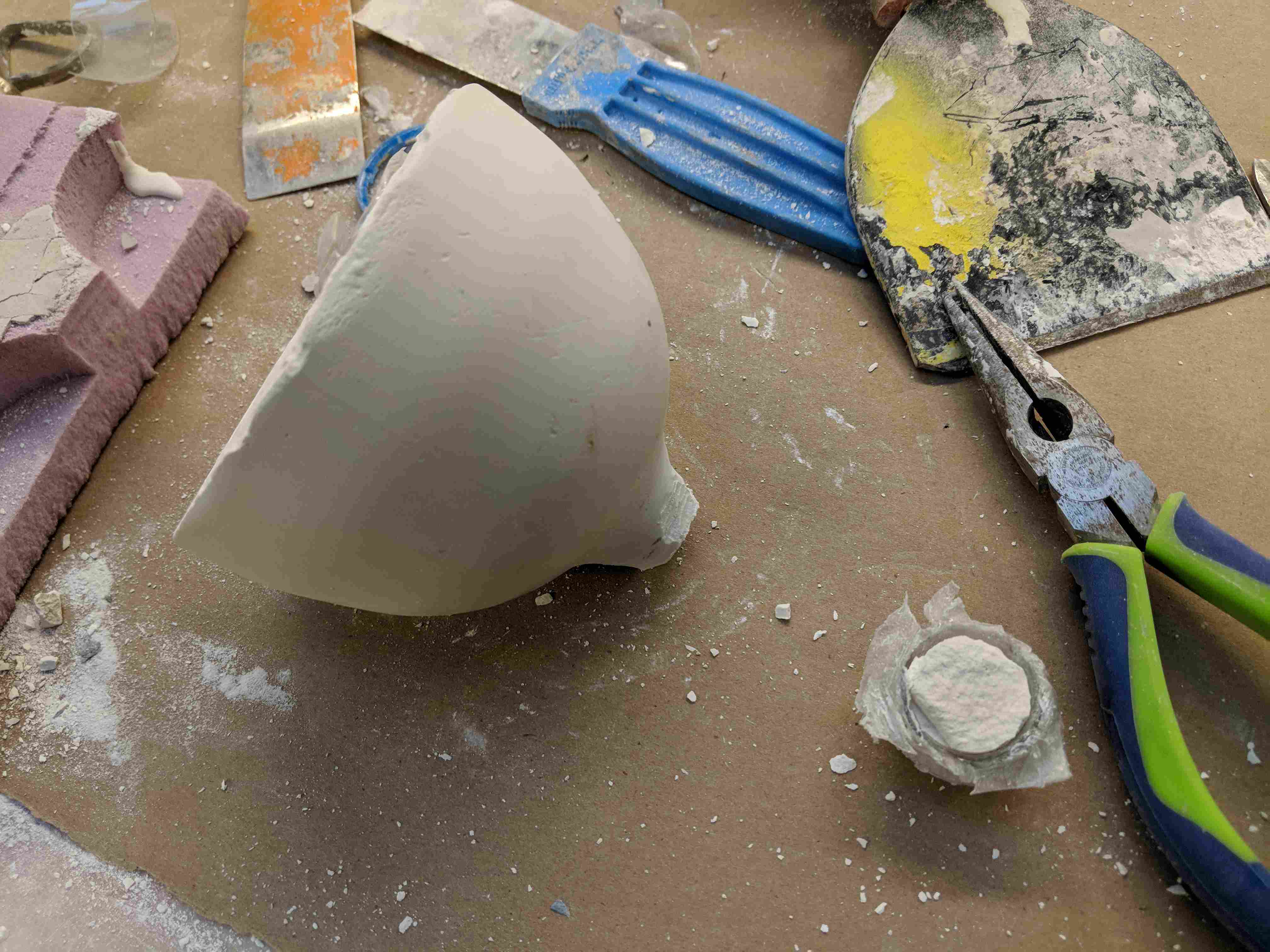
I mixed up the drystone and managed to weigh everything without getting Jen's pretty new scale dirty, but naturally once I started pouring the drystone, the hot glue seal broke. I tried to push it back down, stop it with tape, and even weigh down the inner bottle, but it was too late. I let it dry and came back to a truly unpleasant demolding process. It managed to use all my tactics against me, mixing the tape and the rocks I had used as weights into the solid drystone. It had also leaked into the cap portion of the bottle, which naturally was incredibly difficult to cut off. After a significant amount of time trimming back the bottle and hacking at it with a chisel, I finally broke off the cap portion and then chipped away at the bottom of the remaining cup until I could free the center mold. It was at this point that I decided to make one lamp, not multiple.
Next I spent some time trying to get my boards to program, as I had been unsuccessful for days and needed to consult Calvin. We manage to program the light board and get the LEDs to light up (sorry Calvin if I blinded you a bit), but the remote controller wasn't responding when I tried to program it. The IR receiver also didn't appear to be working, as the output voltage did not vary when we tested it with a generic remote control.
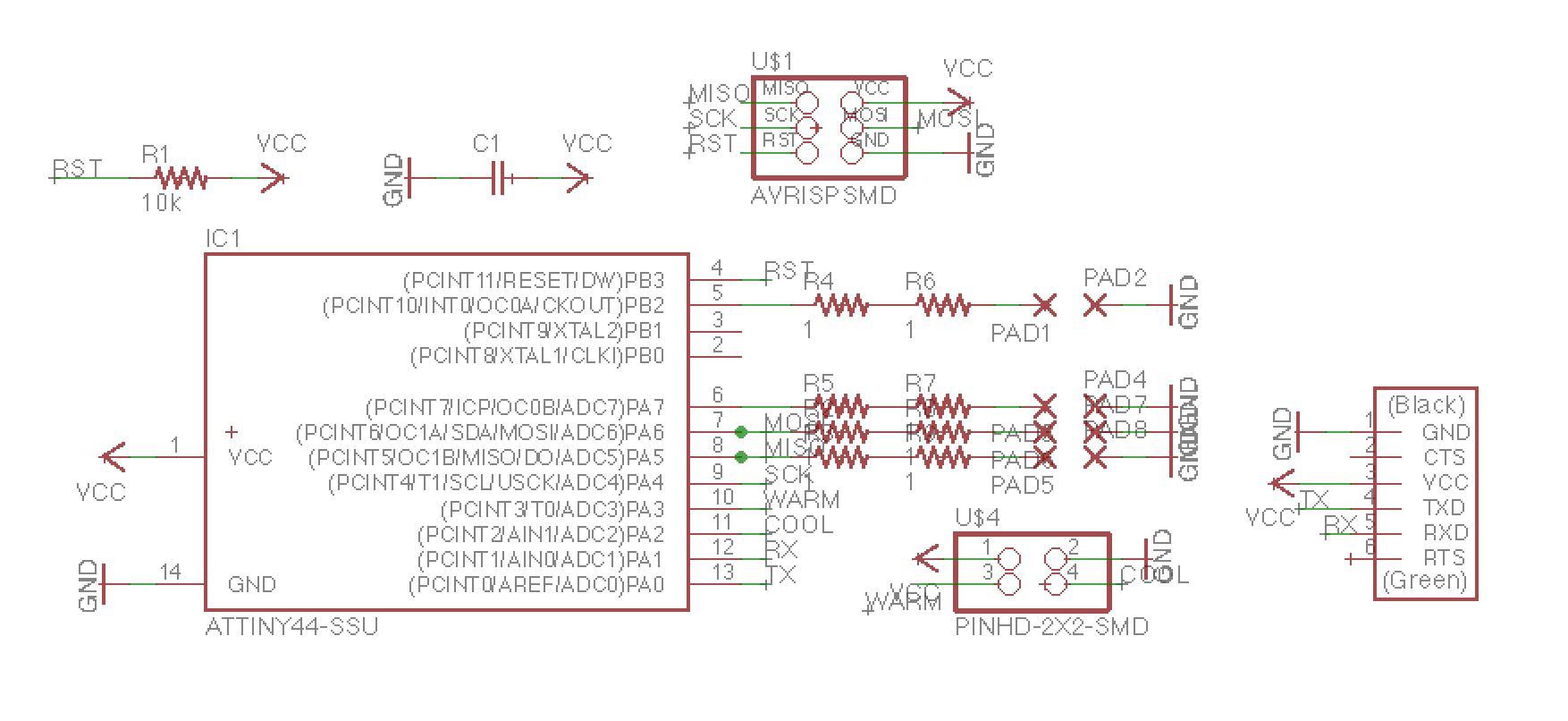
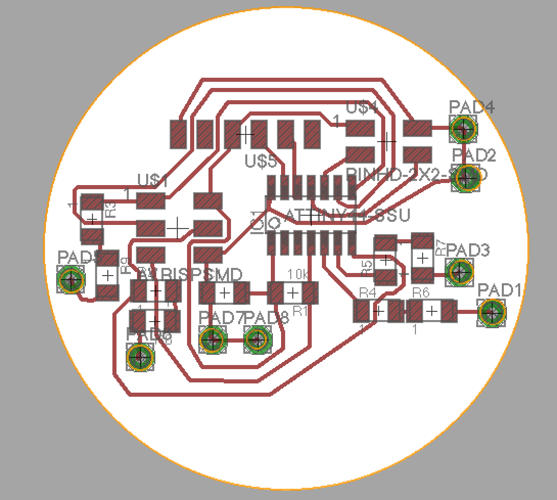
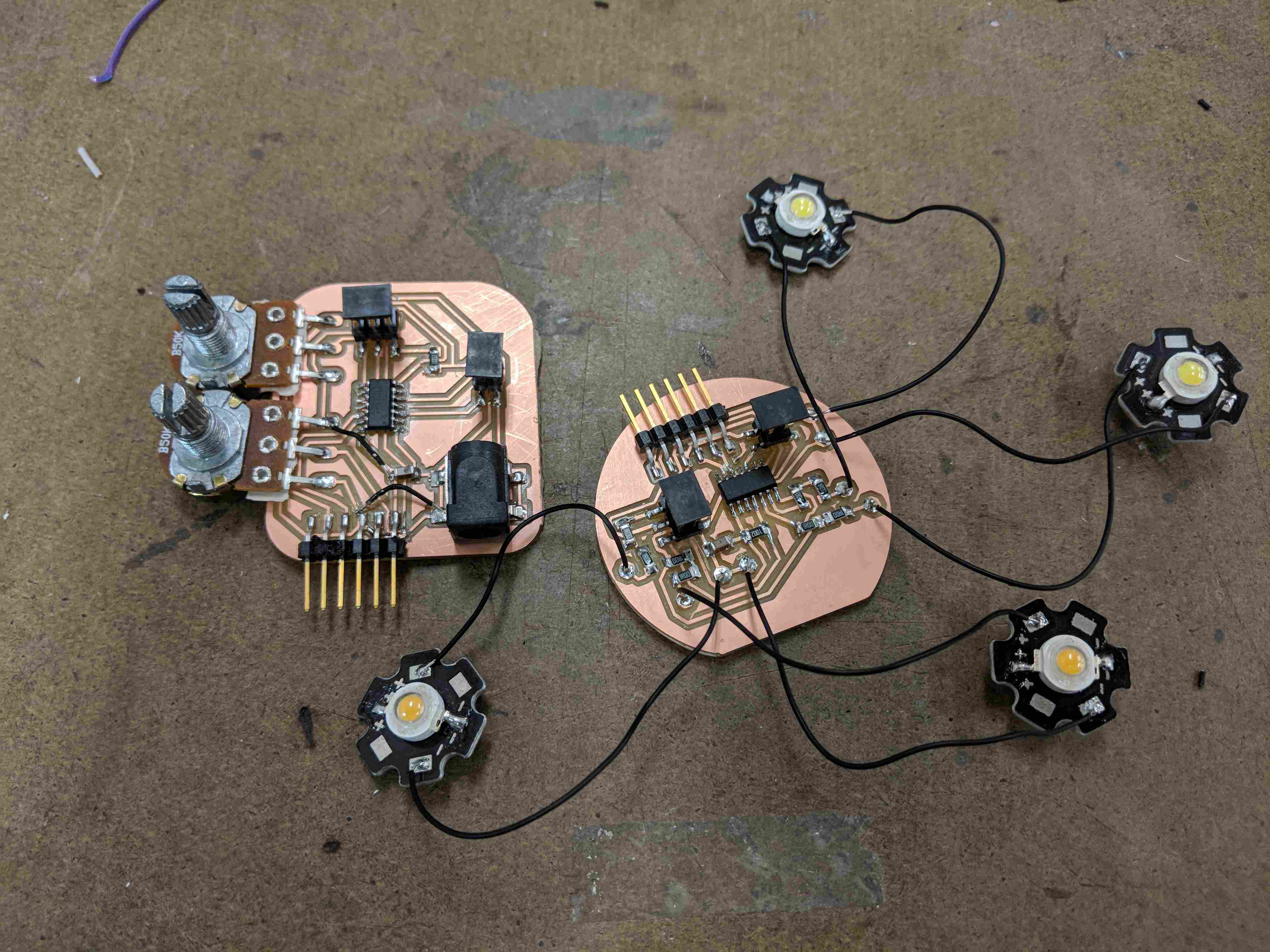
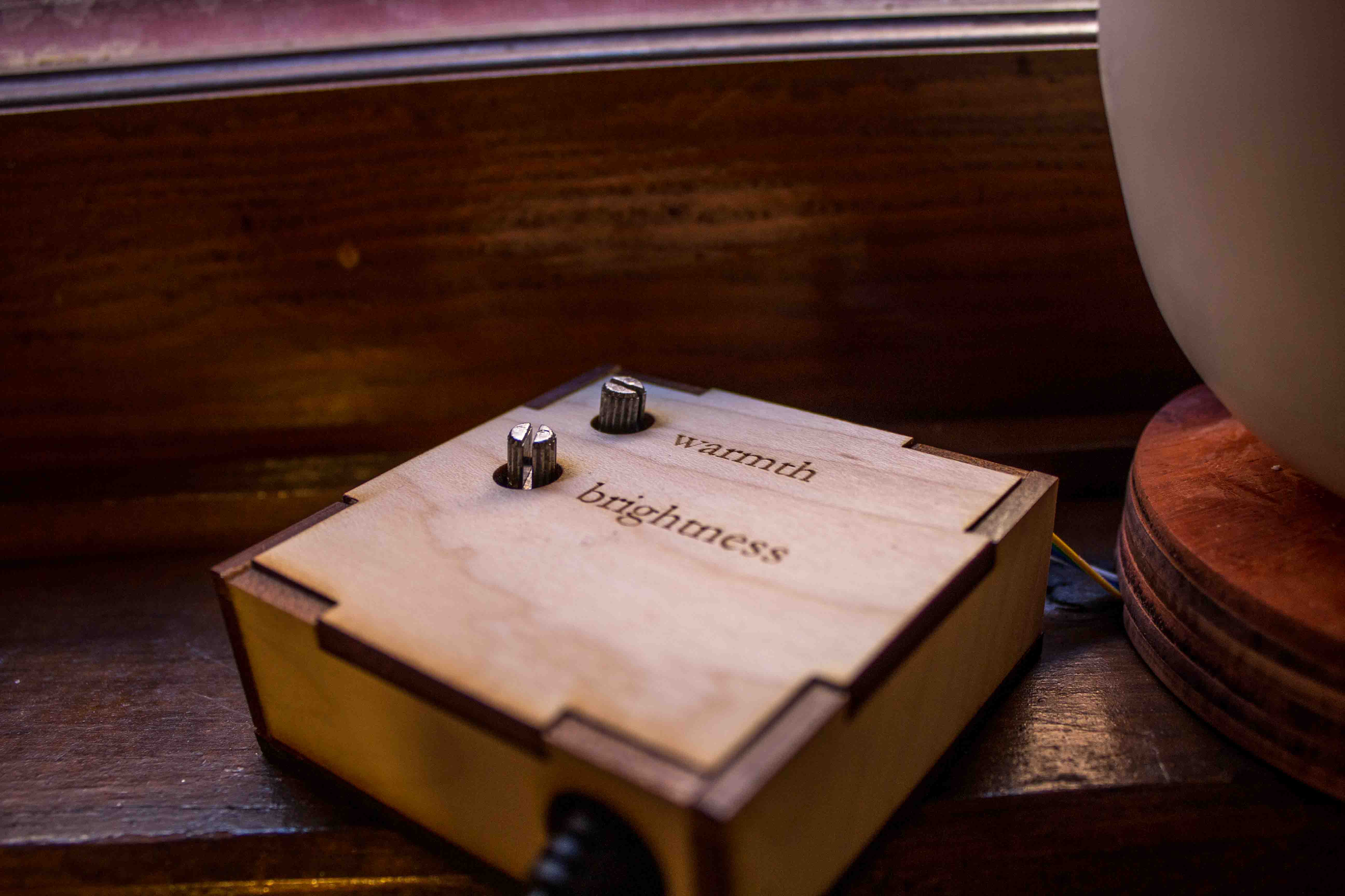
After several hours of debugging attempts, Calvin and I came to the conclusion that I would not be able to get it working in time, so I gave up on the IR and switched to using potentiometers as input devices. I designed and milled some new boards based off the existing ones but with two attinys talking over a cable instead of through IR and two potentiometers instead of three buttons. I also added a second set of LEDs to the light board to make it extra bright.
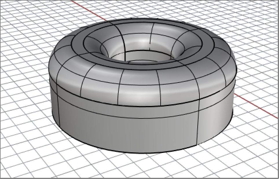
I briefly took a break from the not-so-wonderful world of electronics to mill the saucer for my lamp. I found a nice thick piece of plywood in the scrap bin, quickly modeled a donut-like base in Rhino, and set up the file for the shopbot in MasterCAM with Calvin's help. Unfortunately, the Shopbot was in use so Calvin was gone before I finally got a turn, but Paloma helped me fixture my stock and prep the machine.
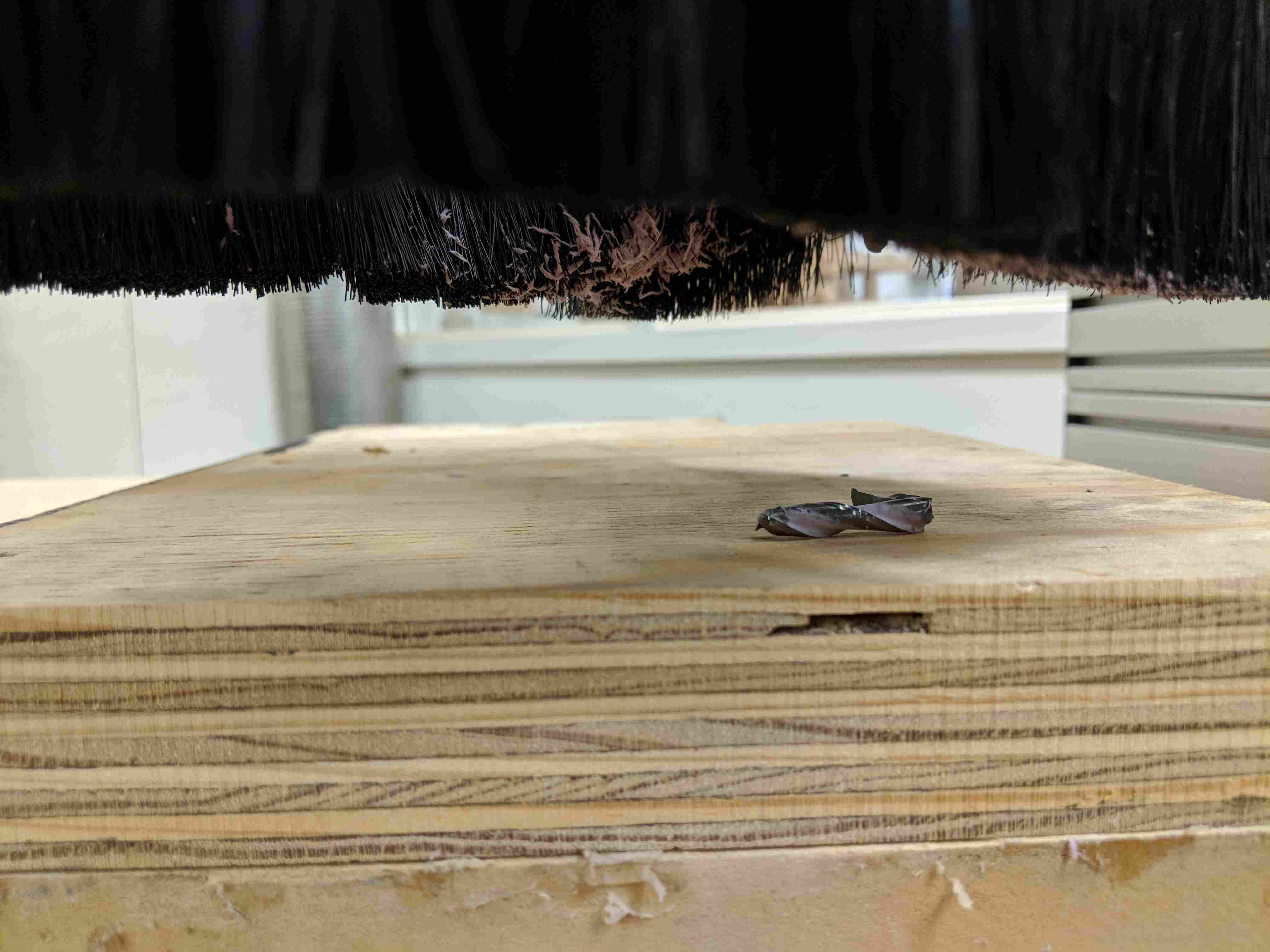
That's when disaster quite literally struck. As soon as the endmill hit the surface of the wood, it cracked into pieces, leaving only a small dent in the wood itself. It's possible that Calvin and I had forgotten to set something in MasterCAM or that the plywood was secretly made of granite, but either way it was late and I was not about to debug the situation, so I decided to switch to laser cutting the base.
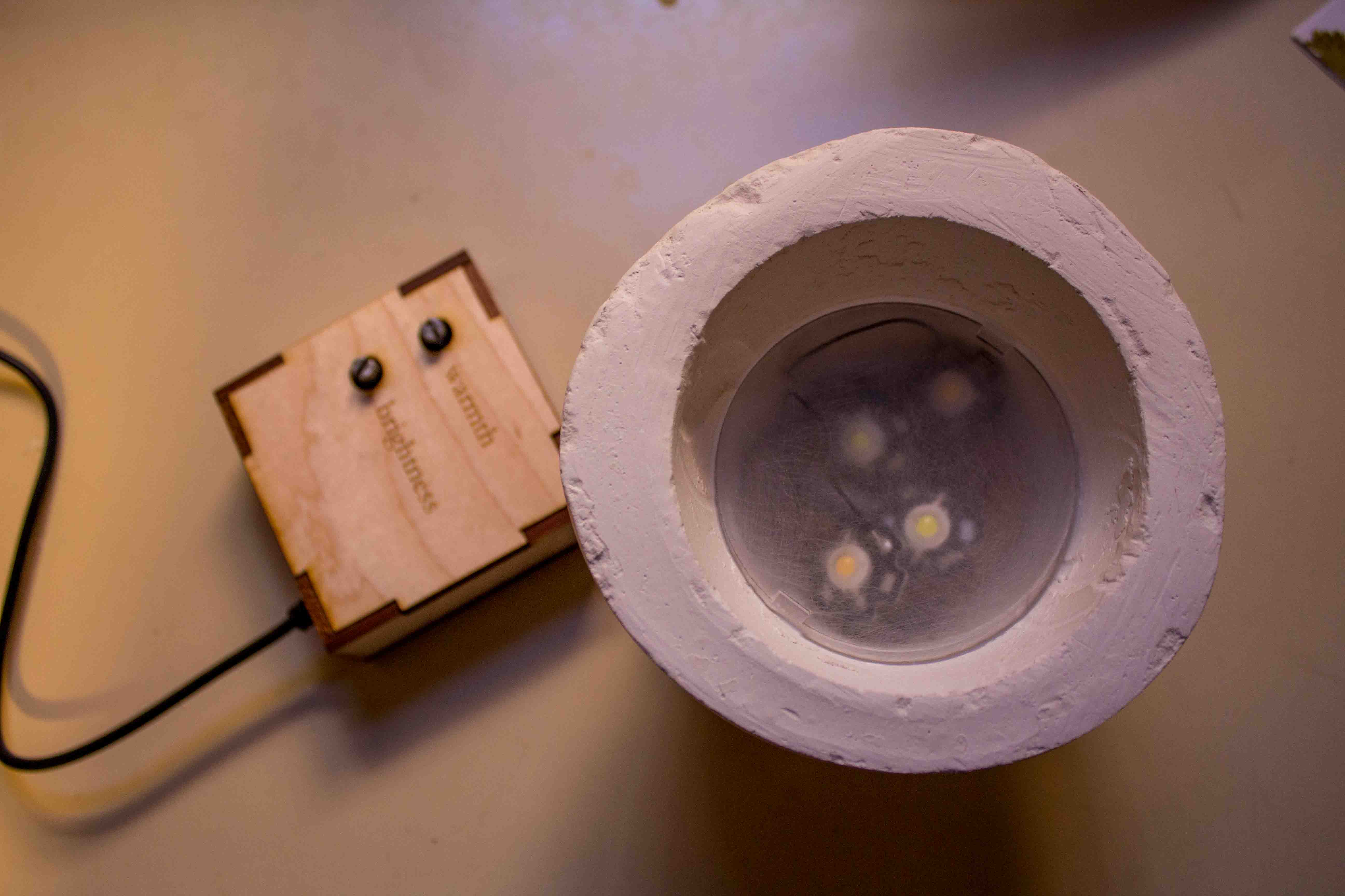
Fortunately, I had some nice 1/8" hardwood that I could laser cut and layer to form the donut-shaped saucer I wanted. I also cut a small channel so that the cord could fit under the base with the base still resting flat. I also cut out a box for the potentiometer board with labels for the two knobs and holes for the cords.
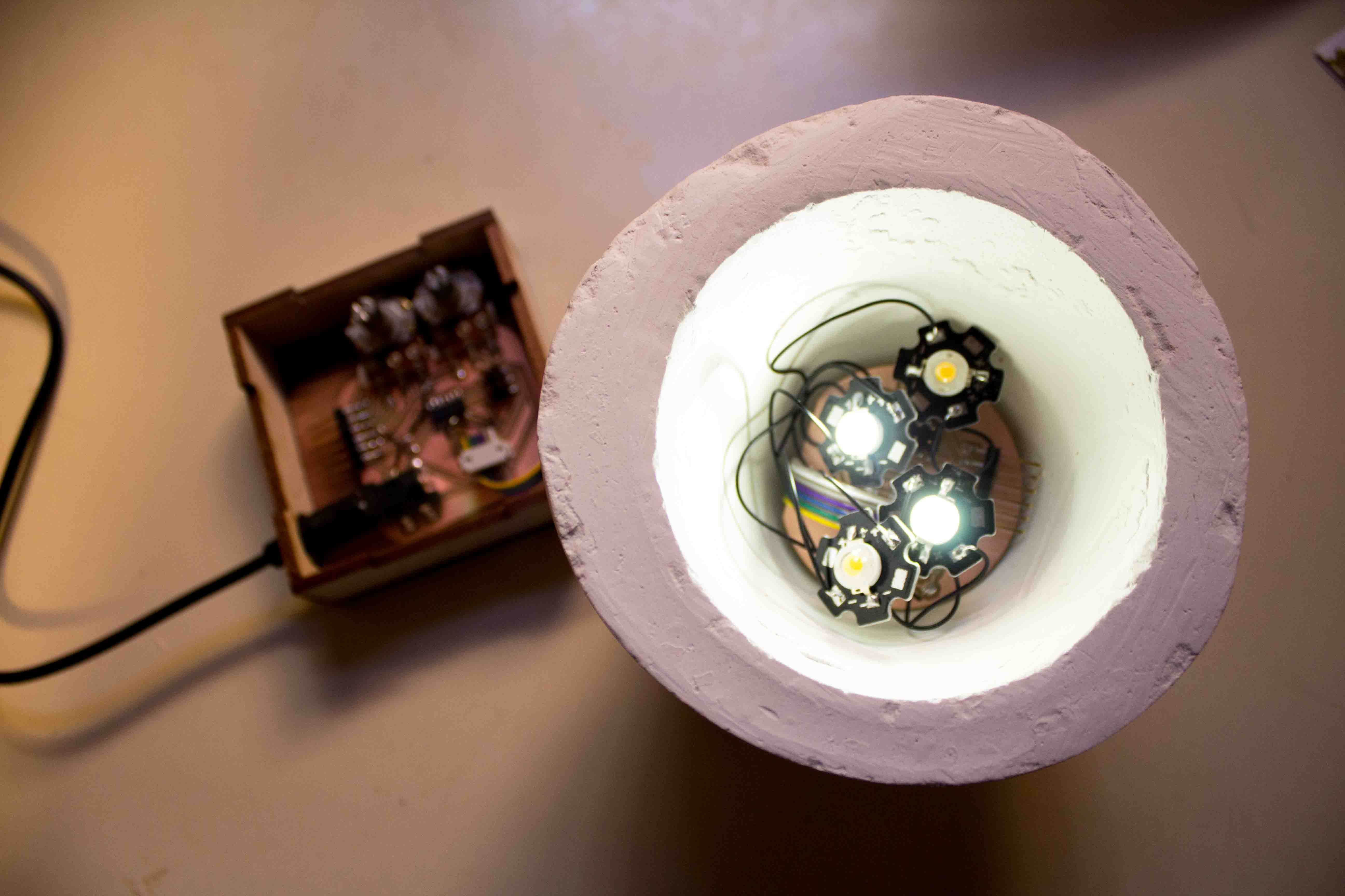
Next, I spent some time programming the boards. I was pretty braindead at this point, so I wasn't able to get them fully working before the final project presentations, but I got them programmed and powered and confirmed that all the LEDs worked. When I turned the potentiometers, the cool LEDs responded, but the warm did not. I spent way too much time trying to debug it, but like I said, I was pretty braindead.
Phase 4: The Final Results
The Potentiometer Board Code:
The Light Board Code:
What does it do?
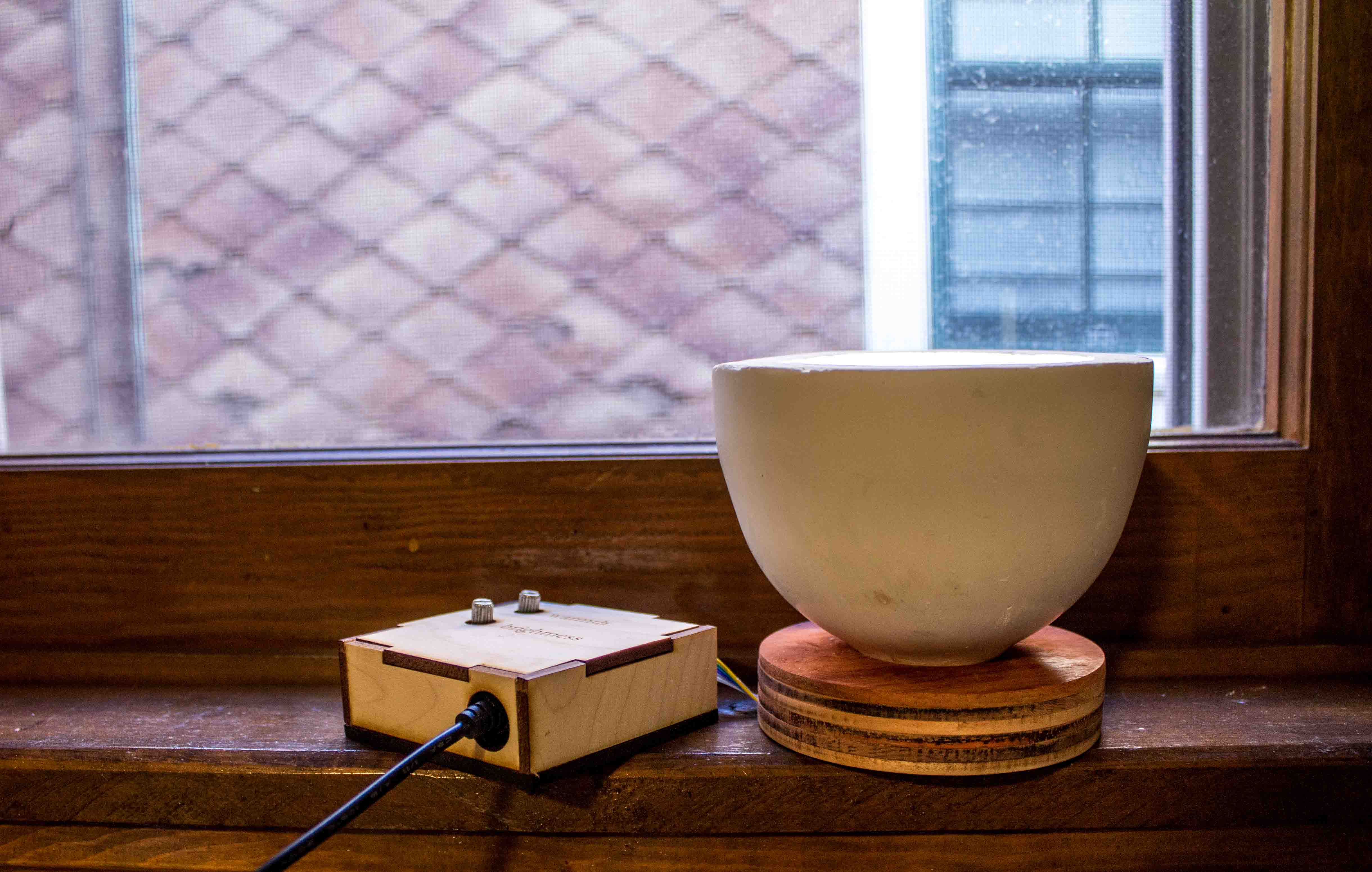
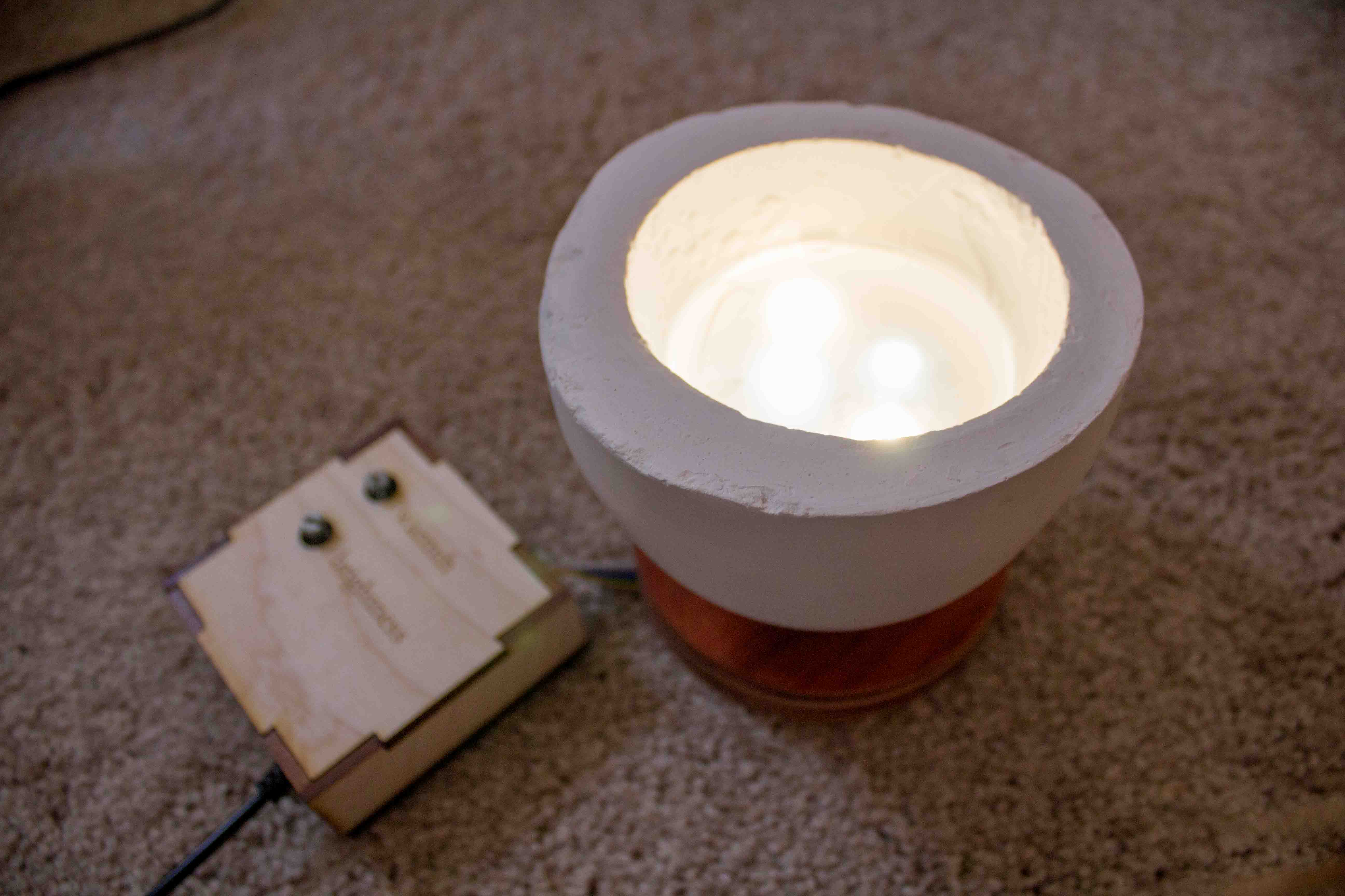
It's a small cup-shaped lamp with an external controller that can be dimmed in both brightness and light color using potentiometers.
Who's done what beforehand?
The concrete cup concept has been used for hanging lights before, but I had not encountered this geometry for a table lamp. Variable white LED lights have also become increasing popular, but they are typically either very expensive "smart" bulbs that require IOT devices to control or they are just a three state bulb that changes with a normal light switch. I wanted to merge these simple concepts in a small, relatively portable way that's cheap and easy to set up.
What did you design?
I designed the wooden base, the controller holder, and both of the boards (plus a dozen other things that didn't work. see above).
What materials and components were used, where did the come from, and how much did they cost?
LEDs - Sparkfun 5 pk. each of warm white and cool white $7.95/pk - used 4
AC to 5V DC converter - Amazon $5.50/each
Wood - hard maple, bloodwood, and padauk Ocooch Hardwoods $21.40 with a lot left over so more like $10
Fab inventory:
Drystone - $13 per gallon, I probably used about $2 worth
Copper boards - <$1
2 Attiny44s - $1
Various headers - $3
Various resistors - <$0.50
Capacitors - <$0.50
Jack - <$1
Loose wire - <$0.50
Solder - <$0.50
2x2 connector cord - $2
Total = ~$33
What parts and systems were made?
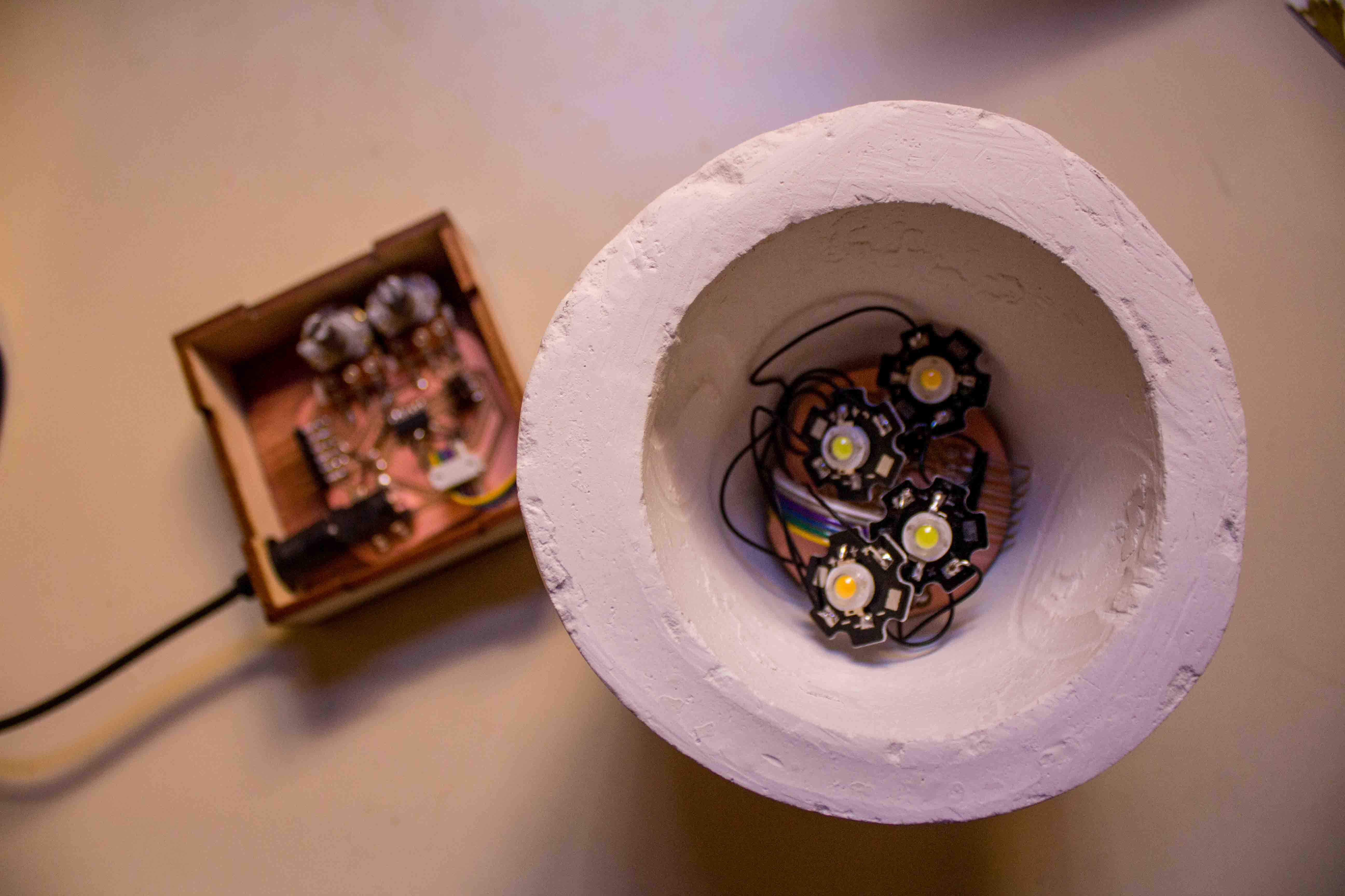
The boards were made, the LEDs were individually connected to the boards. I used a soda bottle as a mold but modified it and cast the drystone. I also laser cut and glued together the wood pieces to form the base and the controller holder.
What processes were used?
CAD CNC Cutting Molding/Casting Electronics Design and Production Embedded Programming Input and Output Devices Networking and Communications
What questions were answered?
Can I make a small lamp bright enough to light up a room? How can I duplicate the power of an IOT enabled smart bulb in roughly half the space?
How was it evaluated?
By the end, my evaluation criteria became fairly simple: Did it light up? Did it look kind of okay? Yes? Good.
What are the implications?
Because I used an external controller, the system is modular and the controller could be replaced with anything from an IR receiver to a light sensor to an IOT device with a bluetooth sensor. My limited electronics skills, while significantly better than at the start of the semester, prevented me from achieving any of these things earlier, but for now I'm content with my potentiometers.
I used to thought that this meant that people who do terrible things typically meant to do good, but now I realize a new meaning: overly ambitious makers with good intentions will find themselves in hell the night before the project is due when suddenly NOTHING WORKS.
My name is Kate Weishaar, and this is my journey.
Phase 1: The Naive Dreams
Original plan:
For my final project, I want to build a chandelier that changes to respond to the user's mood. The quality of light in a room can have a pronounced effect on a user's mood and behavior, depending on factors like brightness, how warm or cool the color is, and whether the light flickers or is constant.
I intend to play with these factors and create a wearable control mechanism in the form of a bracelet or ring that the user can interact with to determine what qualities the light will have. The wearable will have a sensor measuring biological signals like body temperature or heart rate that correlate to mood. It will transmit these signals via IR to the chandelier, which will be programmed to respond with a certain frequency of light.
I will use the output devices week to work out the LED components of the chandelier and get them to respond to sample input data. I will then use the input devices week to figure out how to set up the sensors in the wearable part, and I will use the networking and communications week to connect the two. I will build the physical structure of the chandelier and the wearable using a combination of CNC machining, molding and casting, and 3D printing once I know more about the affordances and constraints of those processes and the corresponding materials.
Revised plan:
In the interest of not pushing my patience with electronics any further than necessary, I decided to scrap the wearable to give myself more time to design the chandelier and fewer points of failure when it comes time to debug. Instead of picking up on the user's mood via a wearable, I will build a small remote control with buttons that indicate different possible moods. This will be much easier to control and will allow me to have preset values that do not need to be calibrated for each wearer. The remote control will have buttons for studying, normal social activities and hanging out, and calming down before bed or when overly stressed. I can still use IR to connect the remote with the chandelier.
I bought some excellent and reasonably cheap cool/neutral/warm white LED bulbs from Home Depot, which I plan to test during output devices week. They work by cycling through the three modes (off->cool->off->neutral, etc.) with a normal switch. I want to hack this switch mechanism so it can be done by the remote control. If I really step up my programming game, I may also find a way to bypass the off and go directly to the desired output, but we'll see.
Update: After breaking the top off of one of the bulbs, I discovered how the bulbs actually work and decided it would probably be easier to make my own (though not necessarily in bulb form). The three color modes were just dictated by three separate sets of tiny LEDs, so that each set only produced a single shade of white. The cool and neutral had more LEDs than the warm, as they were intended to be brighter.
At this point, I'm confident enough in my soldering skills that I could easily build a line or array of LEDs in whatever shape I want, leaving me less constrained form-wise for my chandelier. Creating my own array would also allow me to use PWM to fade between the three sets and achieve a full spectrum of white colors instead of three discrete modes. My next steps will be to design the chandelier itself so I can determine how many LEDs I will need and to design and build a controller that uses a potentiometer to vary the output.
Revised revised plan:
There comes a point in every undergrad's life when she realizes that she is in no position to own a chandelier. Okay maybe that's just me. Anyhow, I decided to make a more tiny-apartment-friendly design: a set of lamps that can be arranged around a room and controlled by a single controller. Each lamp will contain a very bright cool white LED and a very bright warm white LED as well as a controller board that can detect signals from the remote and dim each LED accordingly.
Phase 2: Making it Happen
Once I decided to make a series of networked lamps, I began to figure out what specifically I would need to make. The communication via IR remote would be my main challenge, but I would also need to find appropriately powerful LEDs, determine the necessary resistors and power supply to power the LEDs, design a controller with buttons or a potentiometer to allow for user input, and design the packaging for the controller and the lamps themselves.
I first tried to find LEDs, knowing that the small size of the lamp would constrain my possibilities. I didn't want to use an LED strip because it would not look particularly clean with the geometry, but I also did not want to solder a ton of tiny surface mount LEDs. I ended up finding and ordering packs of warm white and cool white 3W LEDs from Sparkfun.
I then tried to figure out the IR communication. At the time, I did not know the difference between an IR receiver and an IR detector, so I thought the IR detectors in the shop would do the trick. After attempting to build my remote control during networking and communications week, I realized that the IR detector would only detect the whether IR was present, not the specific codes I wanted to send. I then tried to find IR receivers and ended up ordering some on Amazon that I hoped would work ("hoped" here meaning "felt fairly confident about based on reading the datasheet and running it past Calvin", of course).
I then went about designing the various parts of the system: the lamp base, the two boards, and the housing for the remote. The lamp base I wanted to be fairly small and use a mixture of warm wood and white to match my bedroom. My initial thought was to 3-axis mill the wood and cast drystone for the white portion. For the shape, I was inspired by a cup of tea because it too is small and cozy and can brighten moods. I wood create a drystone cup to hold the lights and a wood saucer for the cup to rest in. In the interest of both saving time and creating a super smooth surface finish, I decided to use plastic bottles to create the mold.
I designed the boards to fit into the physical constraints of the system. The light board would have an external receiver board that could read IR signals without be blocked by a wall of drystone, while the light board itself would rest inside the cup. After calculating the current demands of the LEDs I had chosen, I decided that using a 5V AC to DC wall adapter would work much better than batteries, which I would have to change far too often to be practical as a lamp. For the sake of convenience, I put the jack for the power adapter on the external board with the IR receiver. I then added a header to connect the IR receiver board to the light board via a hole in the bottom of the lamp.
For the remote control, I decided to use three buttons: one to make the light color warmer, one to make it cooler, and one to turn it on and off. I stacked the buttons in a line and positioned the IR led so that it would stick out the top for easy aiming, then designed the rest of the board around those spatial constraints.
I also designed the housing for the remote based on the positions of the buttons. I wanted to keep it fairly small, so I planned to remove the headers after programming because they were no longer useful and could be re-soldered fairly easily if needed. The shape was constrained by the position of the IR led, the buttons, and a small battery holder that I had purchased on Sparkfun. 3D printing seemed like the obvious choice because remote controllers are typically plastic, but I wanted something more elegant and visually connected to the lamp itself, so I decided to laser cut the controller housing out of wood and glue it together to make the frame. I also intented to screw the bottom piece onto the remaining stack so that it could be unscrewed when the batteries needed to be changed, but the wood split when I tried to drill into it, and I didn't have time to order smaller screws. I was still quite happy with the wood housing, and I made a gap in the bottom large enough to slide out the battery holder as needed.
Phase 3: How to Break (Almost) Everything
It was in the final push to actually build and program everything that things started going horribly awry. First of all, I ended up moving the weekend before the deadline (awesome timing, right?), which significantly cut down on my work time and resulted in things going mysteriously missing throughout the packing process. Second of all, I realized that no one I know drinks soda, so I ended up having to buy a 2-liter bottle of crappy iced tea just to be able to make a single mold.
When I finally got around to casting, I cut up a 2-liter bottle and a 1-liter bottle and hot glued them to create the mold. I hacked together a stand with scrap foam to hold up the bottle while I poured the drystone, and then I got ready to cast the cup.
I mixed up the drystone and managed to weigh everything without getting Jen's pretty new scale dirty, but naturally once I started pouring the drystone, the hot glue seal broke. I tried to push it back down, stop it with tape, and even weigh down the inner bottle, but it was too late. I let it dry and came back to a truly unpleasant demolding process. It managed to use all my tactics against me, mixing the tape and the rocks I had used as weights into the solid drystone. It had also leaked into the cap portion of the bottle, which naturally was incredibly difficult to cut off. After a significant amount of time trimming back the bottle and hacking at it with a chisel, I finally broke off the cap portion and then chipped away at the bottom of the remaining cup until I could free the center mold. It was at this point that I decided to make one lamp, not multiple.
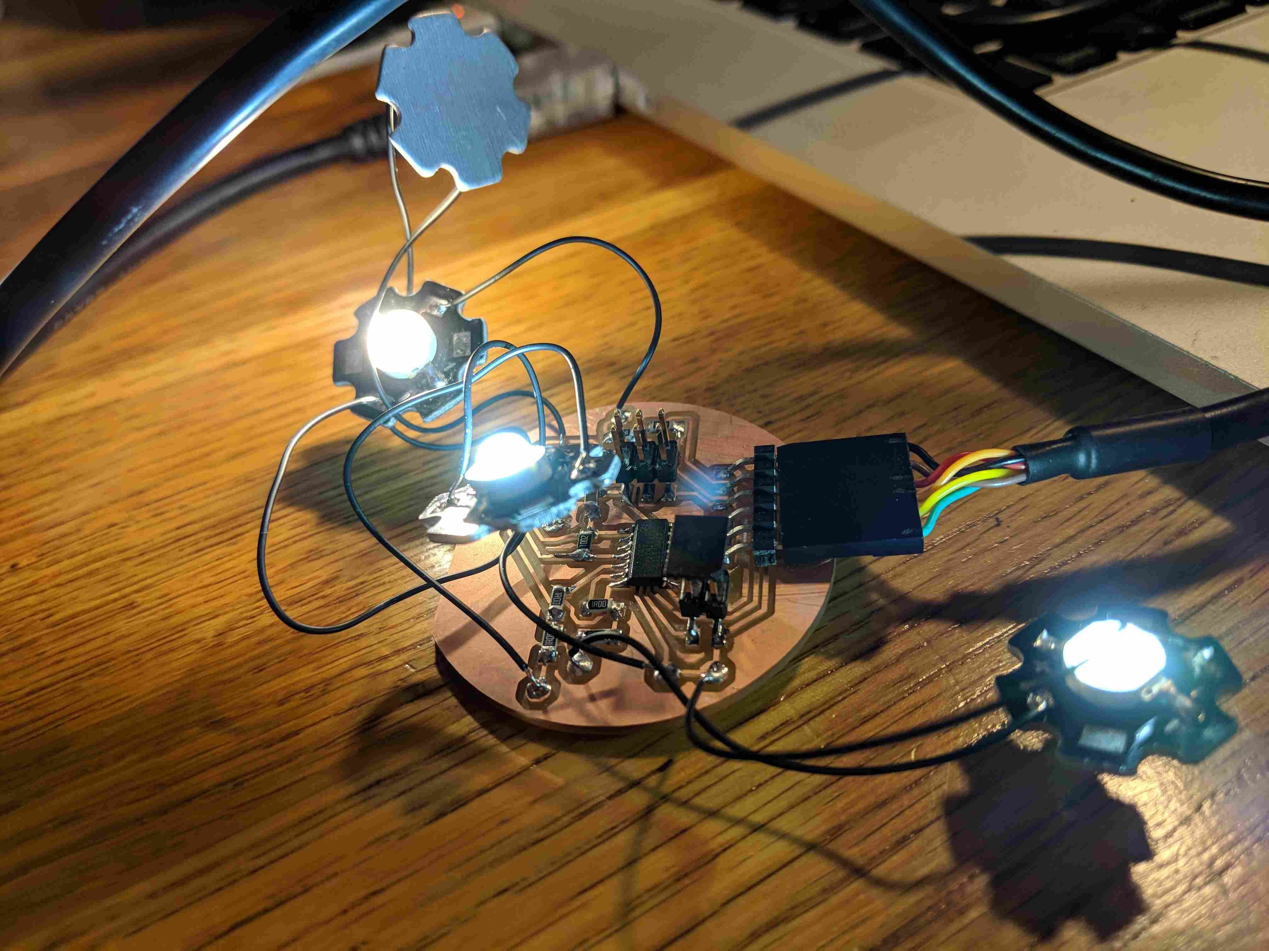
Next I spent some time trying to get my boards to program, as I had been unsuccessful for days and needed to consult Calvin. We manage to program the light board and get the LEDs to light up (sorry Calvin if I blinded you a bit), but the remote controller wasn't responding when I tried to program it. The IR receiver also didn't appear to be working, as the output voltage did not vary when we tested it with a generic remote control.
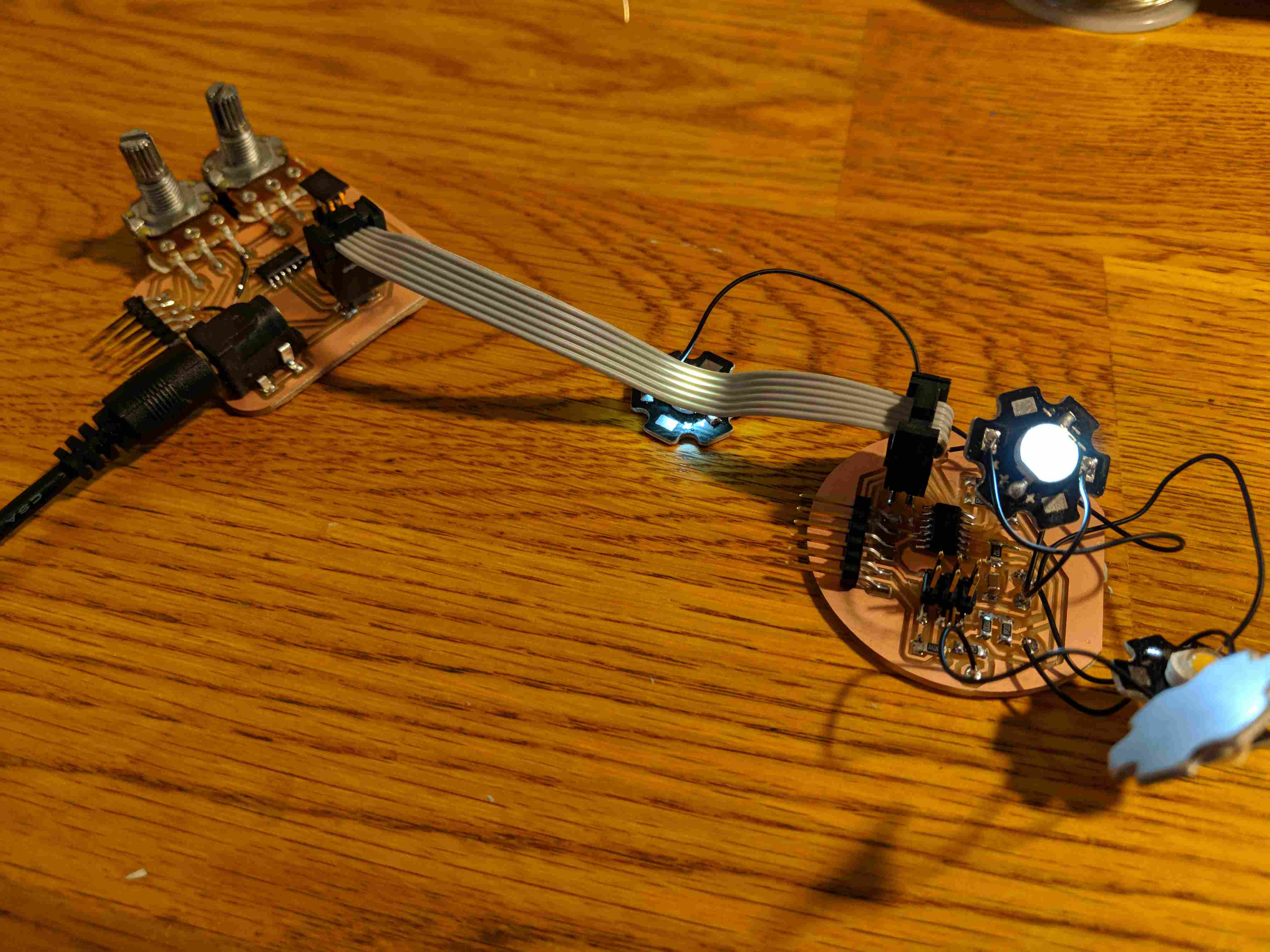
After several hours of debugging attempts, Calvin and I came to the conclusion that I would not be able to get it working in time, so I gave up on the IR and switched to using potentiometers as input devices. I designed and milled some new boards based off the existing ones but with two attinys talking over a cable instead of through IR and two potentiometers instead of three buttons. I also added a second set of LEDs to the light board to make it extra bright.
I briefly took a break from the not-so-wonderful world of electronics to mill the saucer for my lamp. I found a nice thick piece of plywood in the scrap bin, quickly modeled a donut-like base in Rhino, and set up the file for the shopbot in MasterCAM with Calvin's help. Unfortunately, the Shopbot was in use so Calvin was gone before I finally got a turn, but Paloma helped me fixture my stock and prep the machine.
That's when disaster quite literally struck. As soon as the endmill hit the surface of the wood, it cracked into pieces, leaving only a small dent in the wood itself. It's possible that Calvin and I had forgotten to set something in MasterCAM or that the plywood was secretly made of granite, but either way it was late and I was not about to debug the situation, so I decided to switch to laser cutting the base.
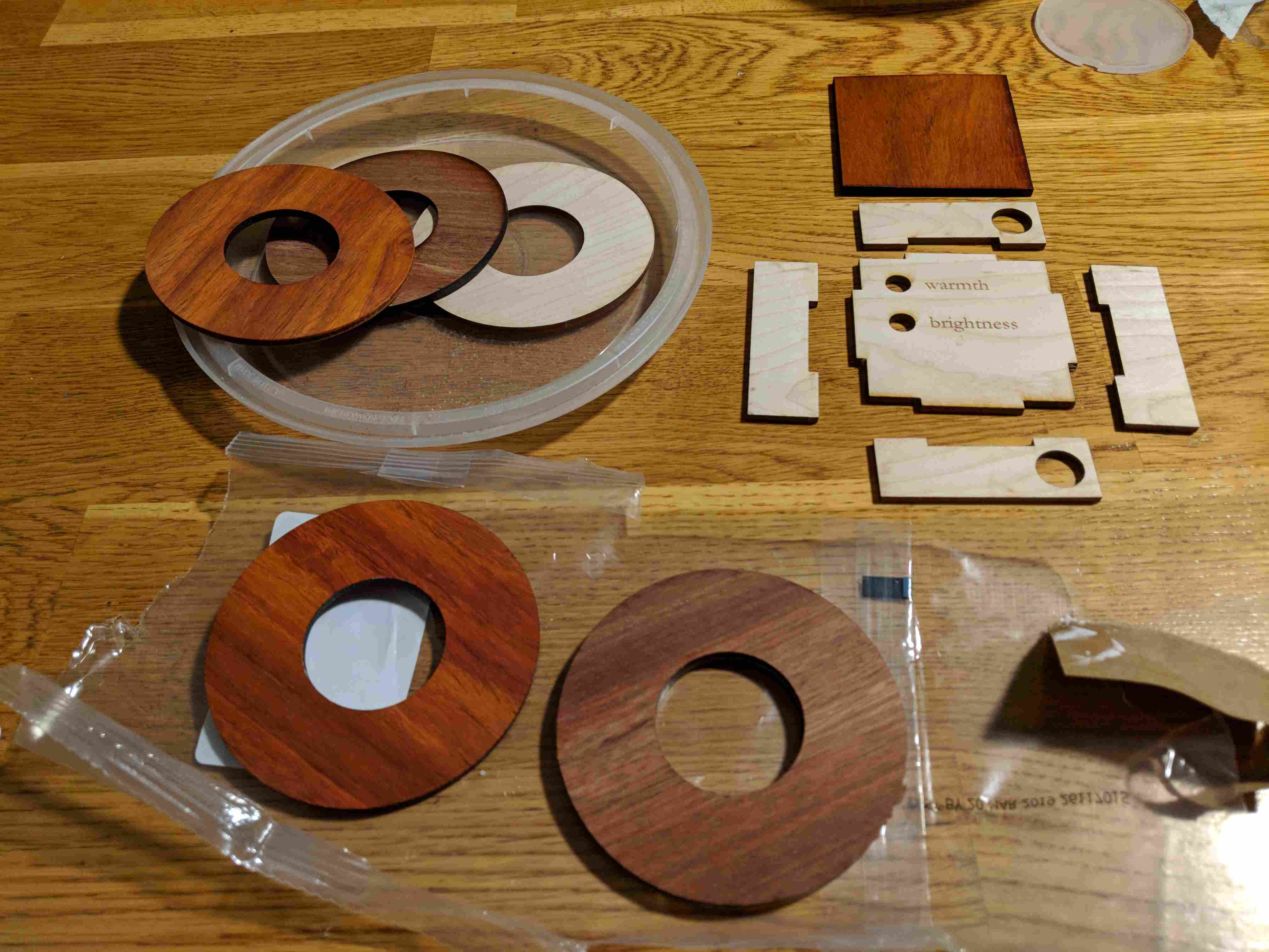
Fortunately, I had some nice 1/8" hardwood that I could laser cut and layer to form the donut-shaped saucer I wanted. I also cut a small channel so that the cord could fit under the base with the base still resting flat. I also cut out a box for the potentiometer board with labels for the two knobs and holes for the cords.
Next, I spent some time programming the boards. I was pretty braindead at this point, so I wasn't able to get them fully working before the final project presentations, but I got them programmed and powered and confirmed that all the LEDs worked. When I turned the potentiometers, the cool LEDs responded, but the warm did not. I spent way too much time trying to debug it, but like I said, I was pretty braindead.
Phase 4: The Final Results
The Potentiometer Board Code:
#include <SoftwareSerial.h> //import SoftwareSerial library (no hardware serial on t44)

#define RX 1 //Set receive pin
#define TX 0 //set transmit pin

SoftwareSerial mySerial(RX, TX); //initialize mySerial

int warmth = 7;
int brightness = 2;
int warm = 8;
int cool = 6;
int warmthVal = 0;
int brightVal = 0;
int total = 255;

void setup() {
  mySerial.begin(9600);
  mySerial.println("Pot Readings");
  pinMode(warmth, INPUT);
  pinMode(brightness, INPUT);
  pinMode(warm, OUTPUT);
  pinMode(cool, OUTPUT);
}

void loop() {
  int new_total;
  int divide;
  int compare_bright = brightVal;
  int compare_warm = warmthVal;
  brightVal = analogRead(brightness);
  warmthVal = analogRead(warmth);
  if (!(brightVal == compare_bright && warmthVal == compare_warm)){
    if (brightVal > 5){
      new_total = map(brightVal, 0, 1023, 0, 255);
      divide = map(warmthVal, 0, 1023, 0, new_total);
      analogWrite(warm, divide);
      analogWrite(cool, new_total-divide);
    }
    else {
      analogWrite(warm, 0);
      analogWrite(cool, 0);
    }
  }
  //mySerial.println(brightVal, warmthVal);
}
The Light Board Code:
#include <SoftwareSerial.h> //import SoftwareSerial library (no hardware serial on t44)

#define RX 1 //Set receive pin
#define TX 0 //set transmit pin

SoftwareSerial mySerial(RX, TX); //initialize mySerial

int warm1 = 5;
int warm2 = 6;
int cool1 = 7;
int cool2 = 8;
int coolin = 2;
int warmin = 3;
int warm_val = 0;
int cool_val = 0;

void setup(){
  mySerial.begin(9600);
  mySerial.println("Light Values");
  pinMode(coolin, INPUT);
  pinMode(warmin, INPUT);
  pinMode(warm1, OUTPUT);
  pinMode(warm2, OUTPUT);
  pinMode(cool1, OUTPUT);
  pinMode(cool2, OUTPUT);
}

void loop(){
  int compare_warm = warm_val;
  int compare_cool = cool_val;
  warm_val = analogRead(warmin);
  cool_val = analogRead(coolin);
  if (compare_warm != warm_val){
//  mySerial.println(warm_val, cool_val);
    analogWrite(warm1, warm_val);
    analogWrite(warm2, warm_val);
  }
  if (compare_cool != cool_val){
    analogWrite(cool1, cool_val);
    analogWrite(cool2, cool_val);
  }
}
What does it do?
It's a small cup-shaped lamp with an external controller that can be dimmed in both brightness and light color using potentiometers.
Who's done what beforehand?
The concrete cup concept has been used for hanging lights before, but I had not encountered this geometry for a table lamp. Variable white LED lights have also become increasing popular, but they are typically either very expensive "smart" bulbs that require IOT devices to control or they are just a three state bulb that changes with a normal light switch. I wanted to merge these simple concepts in a small, relatively portable way that's cheap and easy to set up.
What did you design?
I designed the wooden base, the controller holder, and both of the boards (plus a dozen other things that didn't work. see above).
What materials and components were used, where did the come from, and how much did they cost?
LEDs - Sparkfun 5 pk. each of warm white and cool white $7.95/pk - used 4
AC to 5V DC converter - Amazon $5.50/each
Wood - hard maple, bloodwood, and padauk Ocooch Hardwoods $21.40 with a lot left over so more like $10
Fab inventory:
Drystone - $13 per gallon, I probably used about $2 worth
Copper boards - <$1
2 Attiny44s - $1
Various headers - $3
Various resistors - <$0.50
Capacitors - <$0.50
Jack - <$1
Loose wire - <$0.50
Solder - <$0.50
2x2 connector cord - $2
Total = ~$33
What parts and systems were made?
The boards were made, the LEDs were individually connected to the boards. I used a soda bottle as a mold but modified it and cast the drystone. I also laser cut and glued together the wood pieces to form the base and the controller holder.
What processes were used?
CAD CNC Cutting Molding/Casting Electronics Design and Production Embedded Programming Input and Output Devices Networking and Communications
What questions were answered?
Can I make a small lamp bright enough to light up a room? How can I duplicate the power of an IOT enabled smart bulb in roughly half the space?
How was it evaluated?
By the end, my evaluation criteria became fairly simple: Did it light up? Did it look kind of okay? Yes? Good.
What are the implications?
Because I used an external controller, the system is modular and the controller could be replaced with anything from an IR receiver to a light sensor to an IOT device with a bluetooth sensor. My limited electronics skills, while significantly better than at the start of the semester, prevented me from achieving any of these things earlier, but for now I'm content with my potentiometers.