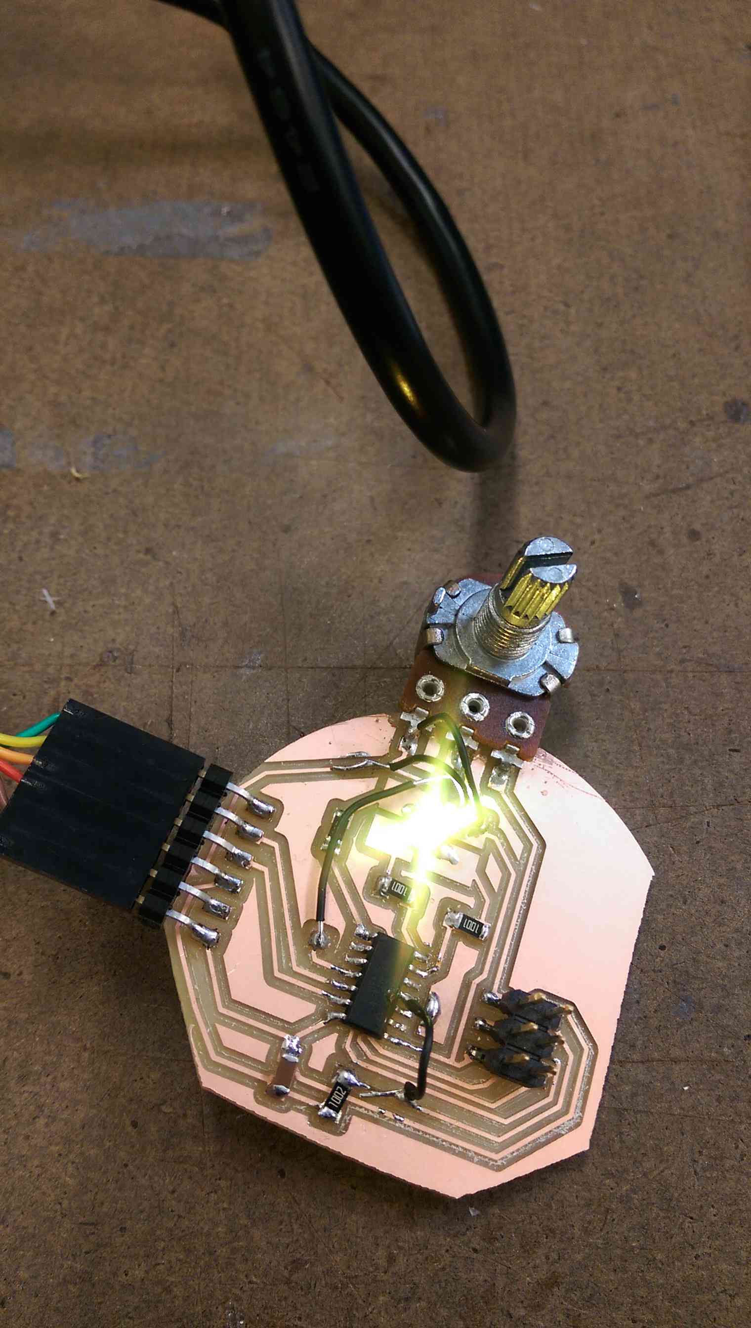
This week we had to add an input device to a board. Because I had been attempting to do that for weeks, I used this as an opportunity to actually succeed, plus sneak it an output device and some embedded programming to redeem my past failures. The board I made is the main part of my remote control for my final project. I will just need to add an IR LED during networking and communications week to make it talk to my lighting components. Other than that, the board consists of a potentiometer to vary the color of the light, and an rgb LED to indicate the chosen color (useful for debugging later if my external lights don't match the onboard LED).
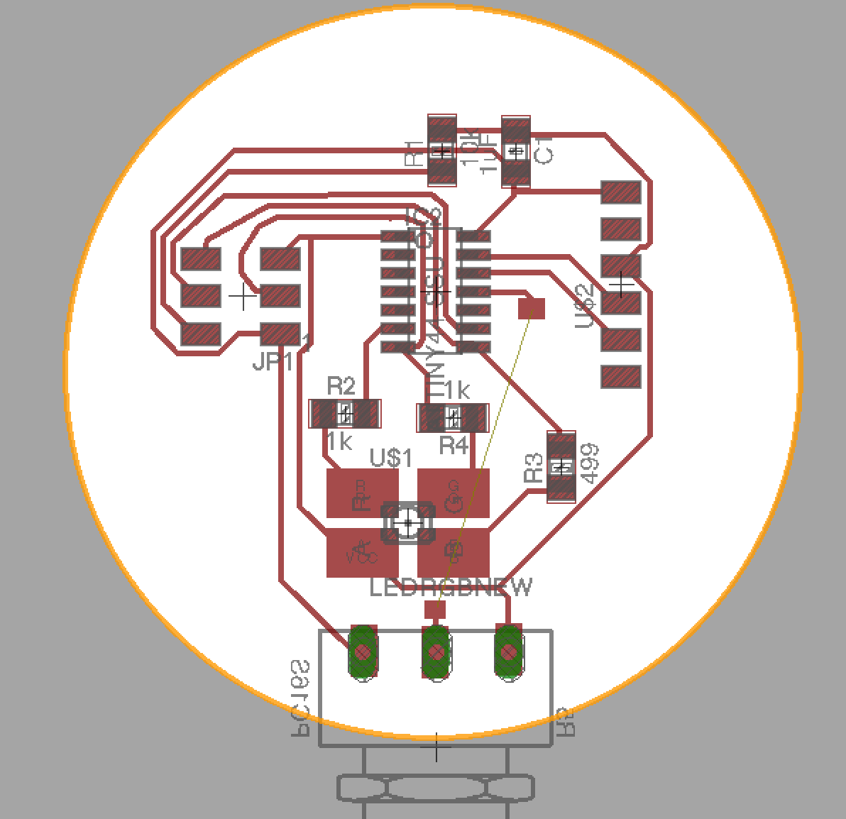

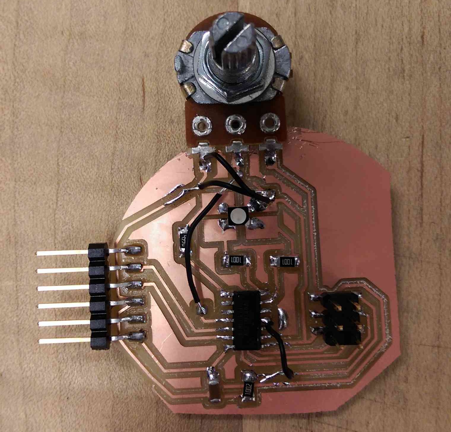
The board turned out to be more of a squished blob than a circle, because the copper came loose while I was milling the outline (a combination of a big sheet, too little tape, and substrate that needed to be replaced). I also needed one jumper for my design, and a couple others to fix some minor errors, so my board was not the prettiest, but it worked!
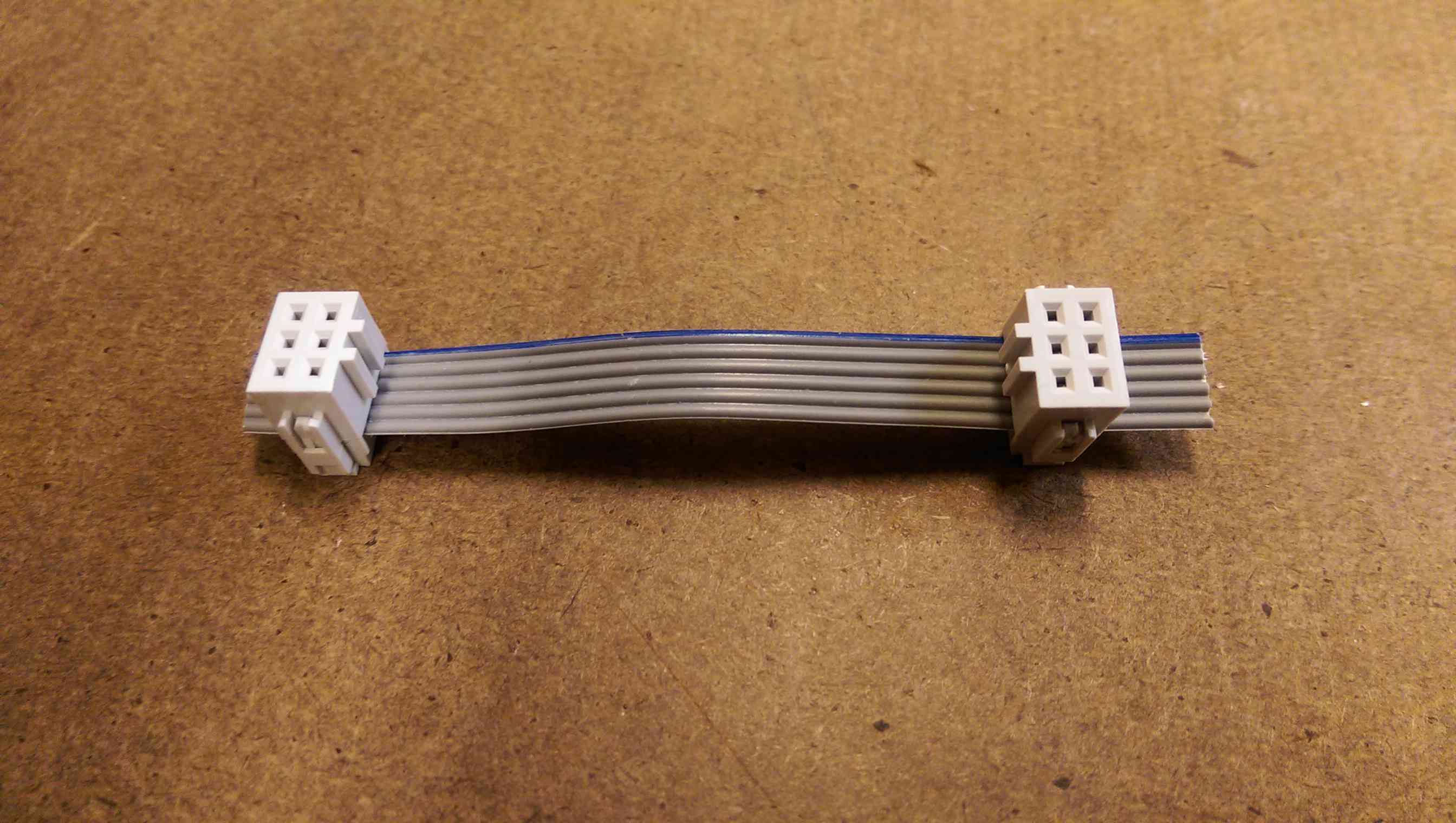
I wanted to program it while I was on campus, but I forgot one of my cords at home, so I got to learn how to make one!
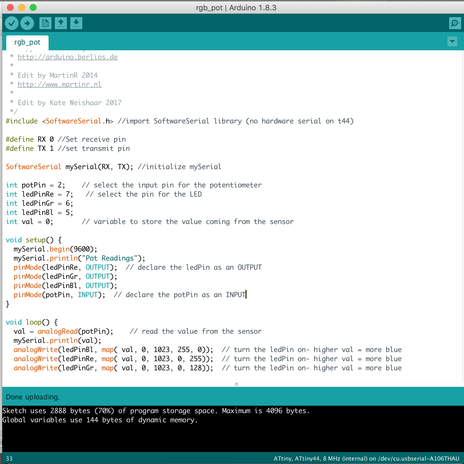
When I got around to programming it, I encountered my old friend rc=-1, but in a moment of "well, it can't hurt", I switched out my fabisp for the first fabisp I had made (which I thought was broken). It turns out, the first fabisp I made worked fine, and the second one was causing problems, even though the computer could recognize it and the LEDs turned on. I wrote some code that would make the potentiometer fade the light from yellow to white to blue and output the values in the serial monitor. With the functional fabisp and enough fidgeting with cords, I was able to successfully program the board from the arduino IDE.
The board turned out to be more of a squished blob than a circle, because the copper came loose while I was milling the outline (a combination of a big sheet, too little tape, and substrate that needed to be replaced). I also needed one jumper for my design, and a couple others to fix some minor errors, so my board was not the prettiest, but it worked!
I wanted to program it while I was on campus, but I forgot one of my cords at home, so I got to learn how to make one!
When I got around to programming it, I encountered my old friend rc=-1, but in a moment of "well, it can't hurt", I switched out my fabisp for the first fabisp I had made (which I thought was broken). It turns out, the first fabisp I made worked fine, and the second one was causing problems, even though the computer could recognize it and the LEDs turned on. I wrote some code that would make the potentiometer fade the light from yellow to white to blue and output the values in the serial monitor. With the functional fabisp and enough fidgeting with cords, I was able to successfully program the board from the arduino IDE.